Article

Operating Characteristics of a Timber Trailer with a Hybrid Drive

1
Department of Engineering, Faculty of Forestry and Wood Technology, Mendel University in Brno, Zemědělská 3, 613 00 Brno, Czech Republic
2
Department of Power Electrical and Electronic Engineering, Faculty of Electrical Engineering and Communication, Brno University of Technology, Technická 12, 616 00 Brno, Czech Republic
3
Institute of Automotive Engineering, Faculty of Mechanical Engineering, Brno University of Technology, Technická 2, 616 69 Brno, Czech Republic
*
Author to whom correspondence should be addressed.
Forests 2022, 13(8), 1317; https://doi.org/10.3390/f13081317
Submission received: 28 July 2022 / Revised: 10 August 2022 / Accepted: 16 August 2022 / Published: 17 August 2022

Abstract

:
This paper deals with the design and operational evaluation of a timber tractor-trailer unit with a hybrid trailer drive. The source of electrical energy for the two induction motors driving the front wheels of the tandem trailer axle is a battery, which is recharged by an induction machine operating as a generator during periods of a lower demand for power from the tractor diesel engine. An electric drive was designed for the defined working cycle of the tractor-trailer unit, and its loading characteristics were tested in the laboratory. The parameters measured on the field tests during timber forwarding were battery voltage and power, and the energy balance. Three adjustment levels of the potentiometer controlling the trailer hybrid drive (50, 75 and 100%) were tested at three different forwarding distances of 100, 500 and 1000 m. Additionally, any slippage of the prime mover wheels and trailer was measured. The maximum peak power taken from the battery was ca. 33 kW during the field tests, whilst the drive was able to deliver a peak output of up to 72 kW for 10 s and permanently up to ca. 50 kW. Even in harsh terrain conditions, the electric drive assisted the combustion engine only when the loaded tractor-trailer unit was travelling uphill. The hybrid drive operation was sustainable for the whole working shift, without the need for recharging when the potentiometer was set to 50%. This appropriate setting of the potentiometer controlling the trailer’s hybrid drive reduced the slipping of the driven wheels of the tractor-trailer unit whilst travelling uphill.

1. Introduction

Explorations for new concepts of vehicle drives are motivated by endeavors to improve the operation of combustion engines by leveling variable loads, which results in the increased efficiency of the drive, reduced fuel consumption and the storage of excess energy. Additionally, the use of a downsized engine can possibly result in a more compact machine layout, leading to better visibility and agility of the machinery components, including a reduction in the noise and vibration levels at the operator’s station [1].
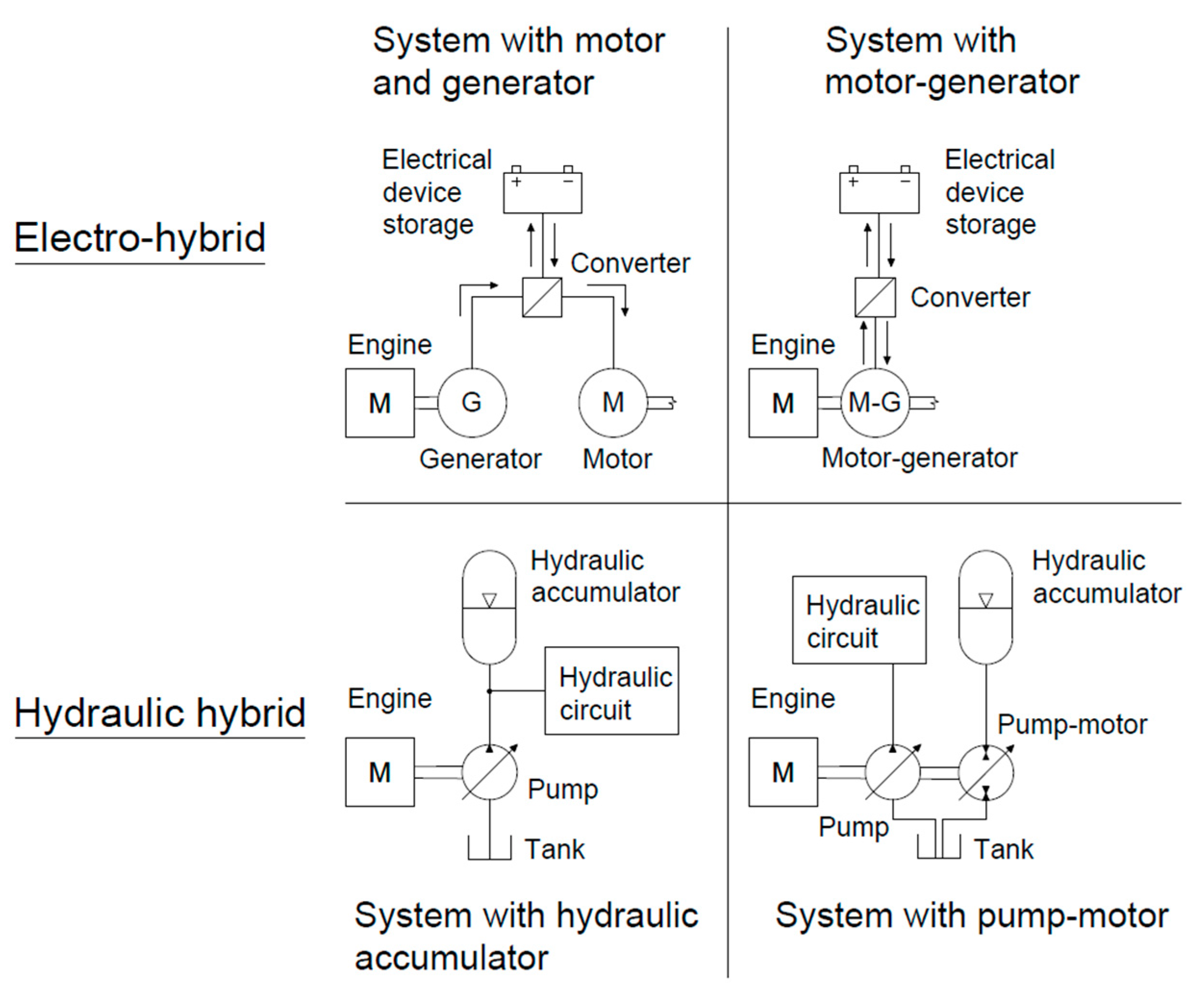
Hybrid systems can currently be classified into three groups based on the type of energy used for their hybridization. Group 1 uses electrical energy to achieve this goal, and this is why these machines are called electro-hybrids. Group 2 uses the pressure energy of liquids, and these machines are referred to as hydraulic hybrids. Group 3 is a combination of the previous two groups, and these machines are called electro-hydraulic hybrids. This group is currently not represented in the forestry sector.
Machines with an electric hybrid system consist of a converter connected to a generator and an electric motor upstream from the electric energy storage (Figure 1) [1]. The electric motor can also function as a generator at the same time [2]. The storage of electrical energy takes place in a battery or via a supercapacitor [3]. A supercapacitor has a higher energy density and longer service life than a battery [4]. Patel et al. [5] also stated that supercapacitors produce a higher output current and voltage. However, the loss of voltage during discharging is faster, as pointed out by Sani et al. [6]. Despite this, the time required for charging the supercapacitor is only 0.3–30 s [4], whilst the battery takes several hours. The correct transmission of the electrical energy between the electric motor, generator and the storage depends on the above-mentioned converter. This component performs the task of changing the parameters of the current and voltage required on input into the storage and on output from the storage to the electric motor. Some pros and cons of machines with electric hybrid systems were published in detail by Minav et al. [7].
There is currently only one electro-hybrid solution implemented in forwarders or timber trailers that is produced by Elforest Technologies AB in cooperation with Volvo Technology Transfer AB. This is the concept of the electro-hybrid forwarder Model F14. The machine employs a combination of an electric motor and generator, which can be called a serial arrangement [2]. The forwarder F14 is composed of three fixed axles that are fitted together with six wheels [8]. One electric motor (30 kW) is mounted on each wheel [9]. All the electric motors are connected to the battery, which is primarily recharged by the generator, located on the shaft of the combustion engine. The battery is secondarily recharged by electrical energy recuperated during the braking of the wheels. The 60 kW combustion engine also powers the hydrogenerators of the crane hydraulic circuit [9]. When the combustion engine is not able to supply sufficient revolutions per minute (RPM) for the hydrogenerator, it is connected through a clutch system to the electric motor, which delivers the RPM required.
Hydraulic hybrid systems use the pressurised energy of liquids whose excessive portion they store. For this purpose, the hydraulic accumulator is used. Nowadays, some solutions in forestry are based on the use of the hydraulic accumulator combined with a hydraulic motor, with the possibility of a generator mode [10]. This hydraulic motor is usually referred to as a hydrogenerator-hydromotor and is mounted on the shaft of the combustion engine. In situations where the loading of the combustion engine is low, the hydrogenerator-hydromotor generates pressurised energy, which is stored in the hydraulic accumulator. In situations where the combustion engine loading is high, the stored energy is released to the hydrogenerator-hydromotor, which converts it into mechanical energy and starts turning the shaft of the combustion engine, by which the load is relieved [11]. The design of the hydraulic hybrids is shown in Figure 1. In the forestry sector, hydraulic hybrids are employed more often than electro-hybrids. All the current solutions are implemented only in forwarders, e.g., Ponsse Plc model Caribou S10 or Hohenloher Spezial-Maschinenbau GmbH & Co. KG model 208F. All these hydraulic systems only employ the design with the hydraulic accumulator, which can be called serial according to Erkkilä et al. [12].
Electro-hybrids or hydraulic hybrids using an electric motor with the generator mode or hydrogenerator-hydromotor are represented neither in forwarders nor in timber trailers, but they are often observed in harvesters, e.g., the Logset 12H GTE [13] electro-hybrid harvester or the hydraulic-hybrid harvester made by Ponsse Plc. [1,10,12].
Auxiliary hybrid drives are not commonly used in timber trailers. There are several hybrid solutions that are mainly focused on the lifting or chipper functions of the trailer, where the hybrid drive reduces the overall dimensions and mass of the hydraulic components, as well as the total fuel consumption [7,14].
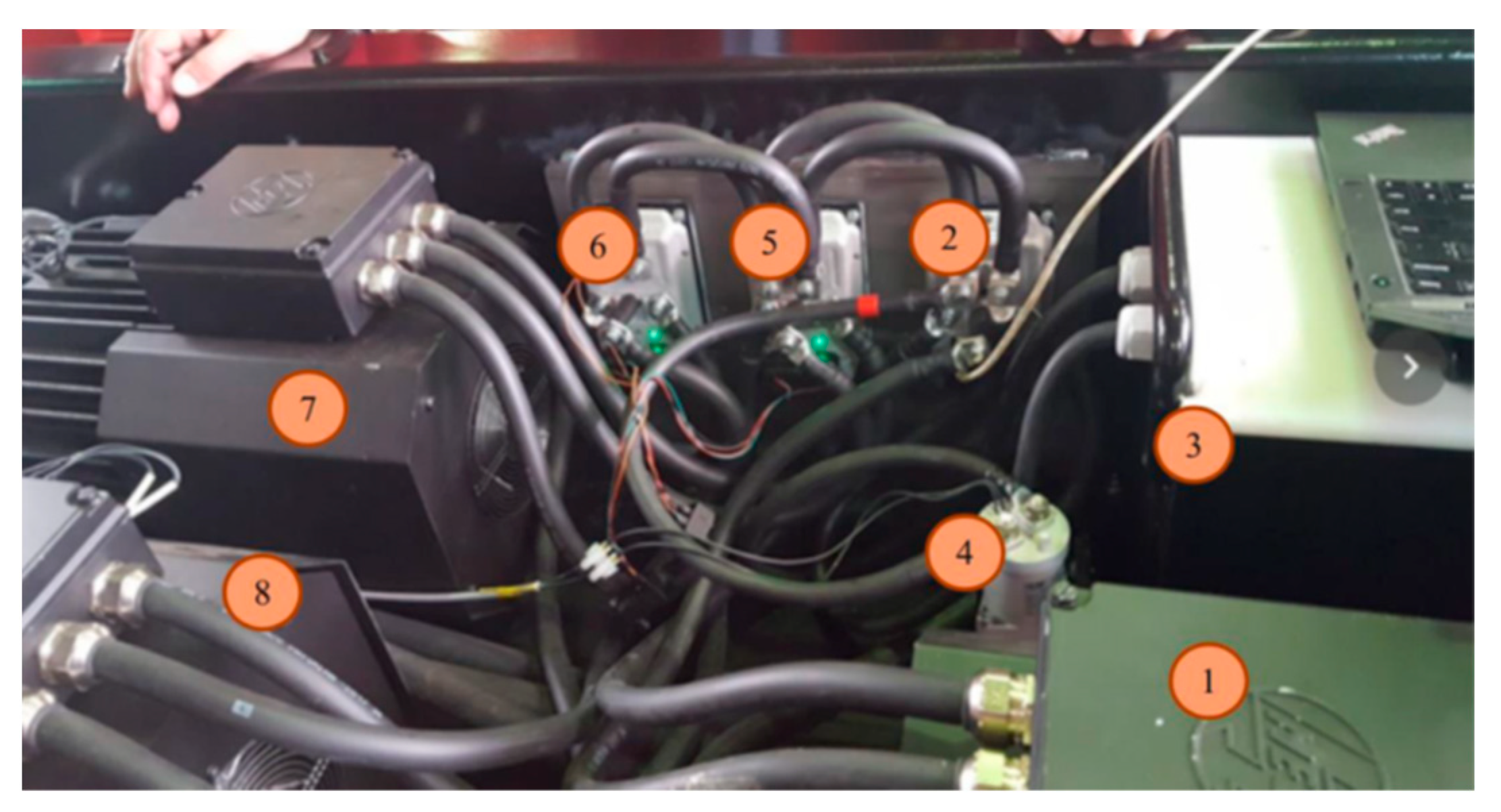
The main reasons for developing the highlighted concept of an electro-hybrid trailer drive (Figure 2) were the possibility of using a prime mover with a lower combustion engine output and the reduction of the tractor-trailer unit operating costs. In addition, the optimized working load of the diesel engine of the tractor would also enable the problem-free passive regeneration of the filtration of the solid particles.
However, the topologies of the hydraulic circuit, with the proportional valves used by default, which control the piston rods of the end facilities, cause considerable losses. According to Minav et al. [7], the overall efficiency of such an arrangement is only seldom higher than 50%. Specifically, under a mild loading of the piston rods and a high speed of movement, great pressure losses occur in the valves, along with losses caused by the high speed of the liquid movement. A possible solution to this problem might be the replacement of the proportional valves with ordinary two-way flaps and directly controlled hydraulic motors operating in all four quadrants. In this way, the losses in the hydraulic circuit can be reduced and energy can be acquired through recuperation. Minav et al. [7] state that the efficiency of heavy machines can be increased in this way by tens of percent.
The characteristics of an auxiliary electric drive are determined primarily by the type of engine and battery, and also by the battery voltage. The influence of the converter on the overall efficiency and properties of the drive is more or less negligible, and the determination of its parameters is determined primarily by the selected battery voltage and by the maximum engine power required. Current hybrid applications mainly employ synchronous and induction motors, which were compared in detail by Bucherl et al. [15] and Finken et al. [16]. It cannot be stated which type of motor is more suitable, as this always depends on the specific requirements of a given application. In general, the induction motor features an inferior power to mass ratio but is more reliable and cheaper. Its efficiency depends on the actual loading and speed. Unlike the synchronous motor, which reaches a higher efficiency at a low speed and high load, the induction motor reaches a higher efficiency at a lower load and higher speed. At the same time, however, the best motor efficiency possible for the given operating conditions can be achieved by means of a control strategy [17,18].
Pohlandt et al. [19] identified the possibility of increasing the electric drive efficiency through the selection of the voltage in the DC link. To avoid the voltage in the DC link being limited by the fixed battery voltage, another DC/DC converter can be inserted between the motor and the battery for the voltage modification. The selection of the optimum voltage is then performed by analyzing the drive working cycle. If the machine is operating most of the time under a light load and at medium or high speeds, then a higher efficiency can be reached at a lower DC link voltage than the efficiency corresponding to the nominal drive point. For a high load, which is typically short-term in nature in working machines, an acceptable efficiency depreciation occurs in the DC link due to the lower voltage. Nevertheless, the overall energy saved during the whole working cycle is higher in the case of a reduced voltage. This principle of increasing the efficiency, however, makes sense only if the electric motor is not controlled by special algorithms in order to reach the maximum efficiency within a wide range of speeds and torques.
Current hybrid topologies use a number of battery types. The technology recently dominating the automotive industry is known as Li-ion. Furthermore, the technology suitable for applications in electric vehicles is that of LFP lithium batteries. This technology allows for the overload of the battery over a short time, which is typically employed for powering the tractor-trailer unit without a markedly reduced service life of the battery. At the same time, it has a good ratio of volume or mass in terms of one kilowatt hour (kWh). This property is, however, not essential for the tractor-trailer unit. Disadvantages of lithium batteries include their higher price and demand for maintenance, which requires a trained operator. Although they also dominate in the field of working machines, there are still some older applications with favorable characteristics in their working environment [20,21]. Many heavy machines still use the Ni-MH, Ni-Cd or even Pb batteries due to their robustness, low price and easy maintenance, which may come at the cost of a higher mass and lower capacity in some applications, as compared with the advanced Li-ion batteries.
It follows that the design of working machines is considerably complicated. Knowledge of the real working cycle of the machine is crucial for the optimum design of all parts of the drive. This can be obtained from actual data of the machine, if it is to be reconstructed into a hybrid or a purely electrical-driven machine. However, if an entirely new machine is to be designed, a realistic loading diagram is very difficult to obtain. With the recent development of computer modelling, there have been efforts to gain information about the real behavior of developed machines by means of mathematical simulators, including the mathematical models of individual machine parts, HIL, SIL or 3D modelling, with AI. Montonen et al. [22] describing the possibility of using advanced modelling techniques to accelerate the optimum development of the electrical components of machines and to test their static and dynamic parameters.
The main goal of this paper is to verify the suitability and functionality of the timber trailer hybrid drive in operation.

2. Materials and Methods

The hybrid drive was installed in the timber trailer, which had a payload of 10 tons. Electrical power was transmitted to the wheels by means of two induction motors with their own hydraulic circuit. During periods of a lower power requirement for tractor power, the battery was recharged by means of an induction machine functioning as a generator, which was connected to a hydraulic circuit of its own.

2.1. Timber Trailer Hybrid Drive

The basic principle block diagram of the electric timber trailer drive is shown in Figure 2. The electric drive can be split into the control and power parts. The power part consists of an electric source (lead-acid battery (3)), which is able to supply the electric drive as well as store electrical energy. The battery choice was selected according to the character of the loading, the volume or mass limitations of the installation in the steering, and the size of the required capacity. Although the LFP batteries have excellent characteristics in many aspects, their need for advanced maintenance is a significant disadvantage in this application. This is why the technology of pure lead was finally more desirable. The reason for this is that these batteries are practically maintenance-free. They are suited to the pulse character of the load, and their price is more favorable in comparison to the lithium batteries. Thus, the power battery of the tractor-trailer unit consisted of SBSC11F cells (from EnerSys company [23]), whose rated capacity was 1.1 kWh at 20 °C. The battery capacity decreased significantly with decreasing temperature, as was tested in the laboratory (see Section 3). The rated voltage of the cell was 12 V. It follows that a necessary voltage of the battery could be reached by connecting 6 cells in the series, with a total voltage of 72 V and a capacity of 6.6 kWh. The battery was kept in an almost fully charged state by the electric generator (1), which was powered by the hydraulic motor fed by the tractor’s hydraulic pump. The generator and two electric motors (7, 8) were chosen as the three phase induction machines. To unify drive components, the same machine was selected for the generator as that used for the wheel drives. The parameters of the chosen motors were verified within a wide speed range by laboratory measurements. The three phase DC/AC converters (2, 5, 6) ensured the proper control of the electric motors and generator in all operational states (motor/generator mode). The DC/AC converter, made by Silixcon SL, with a continuous power of 24.5 kW and a voltage level of 72 V DC, was chosen to supply the electric motors and generator. This converter can be overloaded with an output of 36 kW for a period of 10 s. The DC/AC converters are sufficiently oversized due to their lower resistance to overloading and surrounding heat conditions. The whole power circuit was protected by a power fuse, and the electrical source (battery) could be disconnected from the electric drive by the power circuit breaker. The control part consisted of a main microcontroller, which controlled all the power parts and sensors of the electric drive and cooperated with the higher control system of the timber trailer. The layout of the individual components of the electric drive in the chassis is illustrated in Figure 3.

2.2. Calculations

A work chart of the drive was determined for the optimum design of the electric part of the drive, i.e., the courses of the torque or power were set up within a defined working cycle of the tractor-trailer unit. The loading diagram served to establish the nominal and maximal values of the load of the electric motor, converter and battery. The course of the required loading enabled us to define a suitable topology and size of the battery capacity. The battery dimensions were, at the same time, affected by the limited space designed for the installation of the battery in the trailer. The working cycle of the tractor-trailer unit for the proposed electric drive is presented in Table 1. The electric drive measurements and the verification of the loading characteristics of the drive followed in the laboratory.
A simplified linearized calculation was used to calculate the energy balance of the battery. This calculation is relevant for up to ca. 80% of the battery capacity. When recharged to 100%, the battery significantly increases its internal resistance, and thus it cannot be recharged at full power. In the selected battery, 80% of the capacity is ca. 10.5 kWh, which is still sufficiently greater than the assumed energy consumption required for travelling uphill. According to Plett [24], the battery capacity also strongly depends on the operating temperature. This is why the selected cells were tested in the climatic chamber under different operating conditions.
Based on the working cycle, according to Table 1, the forces and outputs required for the respective operations were calculated. The power required for overcoming the static resistance of the wheel of the tractor-trailer unit is given by the following formula [25]:
P T , s = R   v = ( R s + R t )   v
where R is the total rolling resistance [N] of the wheel of the tractor-trailer unit, which can be broken down into two components, Rs and Rt, and v is the velocity in m·s−1. Rs represents the surface deformation, according to the formula [25]:
R s = C 1   m   g   p ε   D 3
where C1 = 0.5 is a dimensionless experimental constant, generally in the range of 0.35–0.5, m is the vehicle mass [kg], g is the gravity constant [m·s−2], p is the pressure in the tyre [Pa], ε is the coefficient of the subsoil volume deformation [N·m−3] and D is the wheel diameter [m]. The second component in (1) represents the deformation of the tyre itself, according to the formula [25]:
R t = C 2 ( m   g ) 4 p   D 2 3
where C2 = 0.0065 is an experimental constant, according to the recommendation for the working machine in [25] and the other quantities, as in (2).
The most important component for overcoming slope roughness is the power Psl, given by the known formula [25]:
P s l = m   g   v   s i n ( α )
where α is the slope rise in degrees and v is the velocity in m·s−1. Initially, it is also useful to consider the dynamic power given by Newton’s second law of motion. Since the dynamic load is of a short-term nature, it is particularly important for sizing the converter, which has a lower thermal time constant as compared with the other parts of the electric drive.

2.3. Field Measurements

The pumps were driven by electric motors, which drove hydromotors installed in the front wheels of the tandem axle of a trailer, with tyre sizes of 500/45 R22.5 and a tyre inflation of 340 kPa. We selected a tyre tread with properties less aggressive to the ground surface, with lamellas running through the central part of tread in parallel with the transverse axis of the tyre rotation. The load mass (roundwood 4 m in length) was 5700 kg. The total mass of trailer with the load was 11,400 kg. The prime mover was a farm tractor with an engine power of 97 kW, and the dimensions of the front axle wheels were 14.9–28 (tyre inflation of 300 kPa) and those of the rear axle wheels were 18.4–38 (tyre inflation 260 kPa), with tyre tread lamellas running obliquely to the transversal axis of tyre rotation. The drive of the tractor’s front axle was switched off. The farm tractor mass was 8400 kg. The mass of the tractor-trailer unit was determined by weighing the loading of the individual wheels using the portable scales by Haenni, with a measurement range from 0 to 5 tons.
The operating parameters of the hybrid drive of the trailer were tested during the autumn of 2019 in forest stands (spruce monoculture) near the village of Nová Říše (49.1394083 N, 15.5635939 E) in the Czech Republic (Figure 4). The test track was located on an unpaved dirt road—a skidding lane with an average track gradient of 10.7°. The air temperature during the measurements ranged from 12 to 15 °C. The gear engaged in the tractor for driving on the test track was A1, and the tractor engine speed was 1800 RPM.
A series of measurements were performed with different settings of the potentiometer controlling the power of the trailer hybrid drive (50, 75 and 100%) and with different forwarding distances (100, 500 and 1000 m). Each measurement variant was repeated three times. The wheel slip of the prime mover and trailer was measured during each journey. Modified Voltcraft MC-1 mechanical counters (Conrad Electronic Česká Republika, s.r.o., Praha, Czech Republic) were used to register the number of revolutions on the rear driving tractor wheel and on the front (driven) and rear (non-driven) wheel of the trailer tandem axle. The circumferential length of the rear non-driven wheel of the trailer (which was simply rolling and had no slippage) was used as a standard (this was actually the travelled distance) to which the circumferential lengths of the trailer’s driven wheel and driving rear wheel of the tractor were compared. The ratio between the values indicated the degree of slippage, given as a percentage.
At the end of each working cycle of the tractor-trailer unit, the level of battery charge was determined as the percentage of its total capacity.

3. Results and Discussion

The loading diagram of the tractor-trailer unit calculated for one working cycle is shown in Figure 5. The value of the power during the loading and unloading of the logs was determined by the power of the hydraulic crane, Ph = 29.5 kW.
The power values calculated for the individual parts of the working cycle are presented in Table 2. They show that the electric drive assisted the combustion engine only when the loaded tractor-trailer unit was travelling uphill. Thus, the power required by the wheels of the tractor-trailer unit was at least 20 kW. At the same time, the drive had to be capable of increasing the power by ca. 6 kW for a short period (seconds) in order to reach the tractor-trailer unit acceleration required at the start. These values then defined the basic requirements for the individual elements of the electric drive.
The choice of battery voltage is an important part of the design of an electric drive. According to Pohlandt et al. [19], a higher efficiency of the drive can be achieved if a higher level of the battery voltage is chosen with the increasing load. A level of up to 80 V was chosen as the nominal battery voltage, which was selected due to the need to compromise between the high loading of the battery by a sufficient availability of converters for the chosen power level, the risk of electric shock in difficult working conditions, etc.
According to the established loading diagram and the efficiency of the hydraulic drive of the wheels, considered to be ηH = 0.85, the electric drive has to permanently supply a power of ca. 23.5 kW. This value is crucial for the determining the parameters of the electric motor. Induction motors with a rated power of 15 kW and efficiency of η
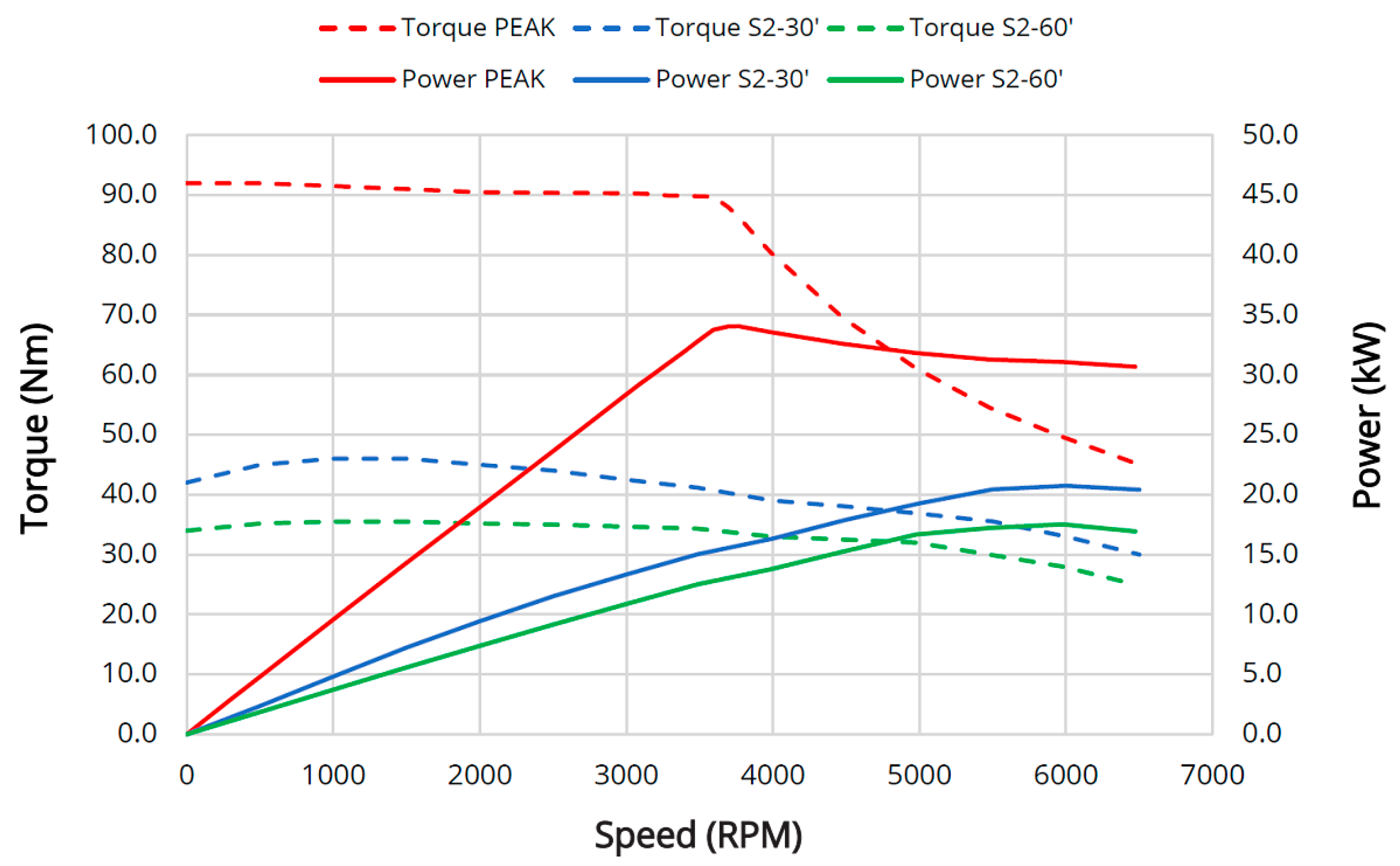
MOT = 0.91 were chosen for the wheel drive. The rated root mean square (RMS) of the motor voltage was 48 V. The total achievable power of the tractor-trailer unit drive on the electric side was subsequently 30 kW. This value provides a sufficient power reserve for the calculated 23.5 kW and, thus, can safely compensate for the possible inaccuracies and negligence of some phenomena (wheel slip, non-homogeneous environment, voltage drop on the battery, etc.) in calculations. The results of the laboratory measurements of the electric drive and the loading characteristics of the drive are presented in Figure 6. They indicate that a lower rated power must be considered for the continuous load (ca. 14 kW) than the one recommended by the manufacturer (15 kW).
The acceleration of the tractor-trailer unit required a short period (several seconds) of power of up to 32 kW. The short-term load is important for determining the parameters of the converter, as this can be overloaded typically only for several seconds compared with the engine, whose time constant of warming is in the tens of minutes.
It follows from the drive topology that the battery could be discharged by a permanent power of up to 33 kW, with the considered overall efficiency of engine and converter being 0.89. However, it could be permanently charged only by a power of 13.4 kW. The total energy of the battery had to be sufficient for one working cycle, as in Figure 5. The calculation of the energy transmitted from the battery to the drive and back also has to take into account the battery efficiency itself of the selected technology, being ηBAT = 0.9. The loading diagram (Figure 5a) shows that energy consumption when driving uphill was about 8.2 kWh, with a medium discharge of power of 25 kW. Thus, at least twelve battery cells connected in the 6S2P configuration had to be used to overcome the requirements of the slope. The total energy of the battery was 13.2 kWh. The courses of the charging and discharging of the battery during the loading cycle are shown in Figure 5b. This means that, while travelling uphill, the battery was being discharged by a medium power of ca. 25 kW, and in the remaining parts of the cycle, it was recharged with a maximum possible power of about 11 kW. The course of the energy balance (Figure 5b) showed that the battery was charged to its full capacity during one loading cycle.
Figure 7 presents the courses of the discharge characteristics of the SBSC11F cell at temperatures of 20 °C, 0 °C and −20 °C. It was also necessary to verify how great the decrease in the battery capacity was with temperature decrease, in comparison to the state at the nominal temperature of 20 °C. Therefore, the battery was firstly measured in a refrigerator (BINDER MK 240) before it was built into the forwarder. Before each test, the battery was charged at 20 °C to a voltage of 13,4 V at standstill. Tests at different temperatures were conducted repeatedly, with a relaxation time of at least 12 h at 20 °C between each charging and discharging. The measurements showed a significant decrease in the capacity dependent on the surrounding temperature. At a temperature of 0 °C, the capacity dropped to 90% of its nominal value, and at a temperature of −20 °C, it fell to 60%. In spite of this distinct decrease in the capacity, it can be assumed that the selected battery is be sufficient for powering the tractor-trailer unit in the chosen loading cycle at a usual temperature of ca. −10 °C.
The installation of an electric drive in the tractor-trailer unit was followed by field tests. The obtained data from the tests confirmed that the estimates of the required power were in line with the maximum values measured during real operation. The courses of the battery power and voltage are shown in Figure 8. The maximum peak power taken from the battery reached ca. 33 kW, with the drive being able to supply a peak power of up to 72 kW for a time of 10 s, and permanently up to ca. 50 kW. Nevertheless, with respect to the battery stress, the power consumption should not exceed ca. 35 kW. The course of the voltage showed that the battery voltage depended on the consumed current. Even at the highest load, there was a sufficient voltage in the battery and, hence, in the DC link of DC/AC converter, which can maintain the required revolutions of the electric motor and, thus, of the hydraulic pump.
One of criteria for assessing the trailer hybrid drive during the field tests was its utilization rate when driving over the difficult terrain during one working shift. At a short distance of 100 m, the operation of the hybrid drive of the trailer performed in a fully sustainable manner at all the potentiometer settings in the given working conditions. When the tractor-trailer unit travelled over a distance of 500 m (Figure 9), the operation of the hybrid drive was sustainable, without additional recharging of the battery, but only if the potentiometer of the power control of the trailer hybrid drive was set to 50%. At the potentiometer setting of 75%, the tractor-trailer unit was able to work throughout the shift. However, at the end of the shift, after seven working cycles, the hybrid drive battery charge was 53% of its full capacity, and the battery had to be recharged before the beginning of the next working shift. When the potentiometer was set to 100%, the hybrid drive of the tractor-trailer unit could be utilized for this forwarding distance only in three working cycles. After these three working cycles, the charge of the battery decreased to 8% of its full capacity. When the tractor-trailer unit travelled over a distance of 1000 m, the long-term operation of the hybrid drive was again sustainable only if the potentiometer was adjusted to 50%. If it was adjusted to 75%, in the selected terrain, the tractor-trailer unit was capable of three journeys with the support of the hybrid drive. Subsequently, the level of the battery charge dropped to 9% of its full capacity. When the potentiometer was set to 100%, the tractor-trailer unit with the hybrid drive was able to realize only one working cycle, after which the level of the battery charge was 10% of its full capacity.
The setting of the potentiometer controlling the power input of the trailer hybrid drive is closely connected with the detected slip rate of the driven wheels of the tractor-trailer unit. With all variants of the potentiometer setting, the highest slip rate was recorded on the rear driven tractor axle. Depending on the potentiometer setting, the average values of the slip on the rear tractor axle ranged from 11 to 43%. The maximum slip (51%) was recorded on the rear tractor axle when the potentiometer was set to 50%. The average slip values of the front wheels of the tandem axle of the trailer ranged from 3 to 9%, according to the potentiometer setting. The maximum slip of 14% was recorded on the front wheel of the tandem axle of the trailer when the potentiometer was set to 100%. The setting of the potentiometer to 100% enabled an increase in the travelling speed of the tractor-trailer unit uphill. However, the minus values of the wheel slip (from −0.3 to −3.1) were also measured on the rear tractor axle. Although this is apparently not an optimal situation (as it testifies to the poor harmonization of the tractor drive and trailer), it demonstrates, at the same time, that the energy of the trailer hybrid drive is sufficient. Table 3 presents a list of the average slip values on the driven wheels of the tractor-trailer unit dependent on the setting of the potentiometer controlling the trailer hybrid drive.
Janulevičius et al. [26] studied the slip of wheels in a tractor-trailer unit travelling through a rut across a flat field in relation to the load mass and the variant of the drive of the wheels of the trailer tandem axle. In a situation where the tractor had the front axle drive off and the tandem axle of the trailer was driven only by the front wheels, the authors recorded slip values on the rear tractor axle of 7.3% and on the front wheels of the trailer tandem axle of 8.5% when travelling with a load. Although our conditions were different (travelling uphill and with a higher mass of the tractor-trailer unit), we recorded a slip of the wheels on the rear axle of the tractor, similar to the aforementioned authors.

4. Conclusions

The field tests of the tractor-trailer unit with the hybrid drive trailer confirmed the accuracy of the individual proposed components of the electric drive. Estimates of the required power values established by calculations and laboratory tests were in line with the maximum values measured in real operation conditions. The maximum peak power taken from the battery was about 33 kW, with the drive being able to supply a peak power of up to 72 kW for the time-period of 10 s, and permanently up to about 50 kW. Even in difficult terrain conditions, the electric drive assisted the combustion engine only when the loaded tractor-trailer unit was travelling uphill.
The setting of the potentiometer controlling the trailer hybrid drive was essential for its possible utilization in timber forwarding during the working shift at different distances. The hybrid drive operation was sustainable over a long period of time (without the need for recharging) for the entire working shift and, at the longest distance of 1000 m, only when the potentiometer was adjusted to 50%. When it was adjusted to 75% or 100%, the usability of the hybrid drive in the selected working conditions was reduced, as compared to the situation in which the hybrid drive could be used for the entire working shift, with a need for its subsequent recharging, to the extent that the utilization of the hybrid drive was limited to only one working cycle. The appropriate adjustment of the potentiometer controlling the trailer hybrid drive made it possible to reduce the slippage of the driven wheels of the tractor-trailer unit whilst travelling uphill. Therefore, the potentiometer setting to values of ≥75% can be generally recommended for sloping terrains or terrains with obstacles, including situations in which there is a potential higher risk of damage to the soil surface due to the slippage of the driven wheels.

Author Contributions

Conceptualization, T.Z. and J.N.; methodology, T.Z., P.P., I.P., J.N., O.V. and R.U.; software, T.Z., P.P. and J.N.; validation, T.Z., P.P., I.P., J.N. and O.V.; formal analysis, T.Z., P.P., I.P., J.N. and O.V.; investigation, T.Z., P.P., I.P., J.N. and O.V.; resources, T.Z., P.P., I.P., J.N., R.U., V.M., L.S. and O.V.; data curation, T.Z., P.P., I.P. and J.N.; writing—original draft preparation, T.Z., P.P., I.P., J.N., V.M., R.U., L.S. and O.V.; writing—review and editing, T.Z., P.P., I.P., J.N., V.M., R.U., L.S. and O.V.; visualization, T.Z., P.P., J.N., V.M. and I.P.; supervision, J.N.; project administration, J.N.; funding acquisition, J.N. and R.U. All authors have read and agreed to the published version of the manuscript.

Funding

This research was funded by the Technology Agency of the Czech Republic, grant number TH02010115.

Institutional Review Board Statement

Not applicable.

Informed Consent Statement

Not applicable.

Data Availability Statement

The data supporting reported results can be found in the article. Additional data are available on request from the corresponding author.

Acknowledgments

This paper uses results from the solution of Project TA CR no. TH02010115, based on a tractor-trailer unit with a hybrid chassis drive for timber transport.

Conflicts of Interest

The authors declare no conflict of interest.

References

  1. Einola, K. Prestudy of a Power Management of a Cut-To-Length Forest Harvester with a Hydraulic Hybrid System. In Proceedings of the 13th Scandinavian International Conference on Fluid Power, Linköping, Sweden, 3–5 June 2013; pp. 71–83. [Google Scholar]
  2. Lajunen, A.; Suomela, J.; Pippuri, J.; Tammi, K.; Lehmuspelto, T.; Sainio, P. Electric and Hybrid Electric Non-Road Mobile Machinery—Present Situation and Future Trends. World Electr. Veh. J. 2016, 8, 172–183. [Google Scholar] [CrossRef]
  3. Xiaoliang, H. Hybrid Energy Storage System for Electrical Vehicles Using Battery and Super Capacitor. Ph.D. Thesis, University of Tokyo, Tokyo, Japan, June 2014. [Google Scholar]
  4. Hromádko, J. Speciální Spalovací Motory a Alternativní Pohony: Komplexní Přehled Problematiky pro Všechny Typy Technických Automobilních Škol, 1st ed.; Grada Publishing a.s.: Prague, Czech Republic, 2012; pp. 1–160. [Google Scholar]
  5. Patel, K.R.; Desal, R.R. Calculation of Internal Parameters of Super Capacitor to Replace Battery by Using Charging and Discharging Characteristics. Int. J. Eng. Innov. Technol. 2012, 2, 142–146. [Google Scholar]
  6. Sani, A.; Siahaan, S.; Mubarakah, N.; Suherman, S. Supercapacitor performance evaluation in replacing battery based on charging and discharging current characteristics. IOP Conf. Ser. Mater. Sci. Eng. 2018, 309, 012078. [Google Scholar] [CrossRef]
  7. Minav, T.; Laurila, L.; Pyrhönen, J. Energy recovery efficiency comparison in an electro-hydraulic forklift and in a diesel hybrid heavy forwarder. In Proceedings of the SPEEDAM 2010, Pisa, Italy, 14–16 June 2010; pp. 574–579. [Google Scholar] [CrossRef]
  8. Edlund, J.; Bergeten, U.; Lögren, B. Effects of two different forwarder steering and transmission drive systems on rut dimensions. J. Terramech. 2012, 49, 291–297. [Google Scholar] [CrossRef]
  9. Stoddart, N. El-forest hybrid forwarder. For. J. 2010, 10, 20–21. [Google Scholar]
  10. Linjama, M.; Huova, M.; Tammisto, J.; Heikkilä, M.; Tikkanen, S.; Kajaste, J.; Paloniitty, M.; Pietola, M. Hydraulic hybrid working machines project—Lessons learned. In Proceedings of the 16th Scandinavian International Conference on Fluid Power (SICFP 2019), Tampere, Finland, 22–24 May 2019; pp. 423–437. [Google Scholar]
  11. Einola, K.; Kivi, A. First experimental results of a hydraulic hybrid concept system for a cut-to-length forest harvester. In Proceedings of the 14th Scandinavian International Conference on Fluid Power, Tampere, Finland, 20–22 May 2015; pp. 52–64. [Google Scholar]
  12. Erkkilä, M.; Bauer, F.; Feld, D. Universal Energy Storage and Recovery System—A Novel Approach for Hydraulic Hybrid. In Proceedings of the 13th Scandinavian International Conference on Fluid Power, Linköping, Sweden, 3–5 June 2013; pp. 45–52. [Google Scholar]
  13. Logset Oy. Logset 12H GTE Hybrid. Available online: https://logset.fi/12h-gte-hybrid (accessed on 4 July 2022).
  14. Prinz, R.; Laitila, J.; Eliasson, L.; Routa, J.; Järviö, N.; Asikainen, A. Hybrid solutions as a measure to increase energy efficiency—Study of a prototype of a hybrid technology chipper. Int. J. For. Eng. 2018, 29, 151–161. [Google Scholar] [CrossRef]
  15. Bucherl, D.; Nuscheler, R.; Meyer, W.; Herzog, H. Comparison of electrical machine types in hybrid drive trains: Induction machine vs. permanent magnet synchronous machine. In Proceedings of the 2008 18th International Conference on Electrical Machines, Vilamoura, Portugal, 6–9 September 2008; pp. 1–6. [Google Scholar] [CrossRef]
  16. Finken, T.; Felden, M.; Hameyer, K. Comparison and design of different electrical machine types regarding their applicability in hybrid electrical vehicles. In Proceedings of the 2008 18th International Conference on Electrical Machines, Vilamoura, Portugal, 6–9 September 2008; pp. 1–5. [Google Scholar]
  17. Li, Z.; O’Donnell, D.; Li, W.; Song, P.; Balamurali, A.; Kar, N.C. A Comprehensive Review of State-of-the-Art Maximum Torque per Ampere Strategies for Permanent Magnet Synchronous Motors. In Proceedings of the 2020 10th International Electric Drives Production Conference (EDPC), Ludwigsburg, Germany, 8–9 December 2020; pp. 1–8. [Google Scholar] [CrossRef]
  18. Uddin, M.N.; Nam, S.W. New Online Loss-Minimization-Based Control of an Induction Motor Drive. IEEE Trans. Power Electron. 2008, 23, 926–933. [Google Scholar] [CrossRef]
  19. Pohlandt, C.; Geimer, M. Variable DC-link voltage powertrain for electrified mobile work machines. In Proceedings of the 2015 International Conference on Electrical Systems for Aircraft, Railway, Ship Propulsion and Road Vehicles (ESARS), Aachen, Germany, 3–5 March 2015; pp. 1–5. [Google Scholar] [CrossRef]
  20. Williamson, S.S.; Khaligh, A.; Oh, S.C.; Emadi, A. Impact of energy storage device selection on the overall drive train efficiency and performance of heavy-duty hybrid vehicles. In Proceedings of the 2005 IEEE Vehicle Power and Propulsion Conference, Chicago, IL, USA, 7 September 2005; p. 10. [Google Scholar] [CrossRef]
  21. Gao, Y.; Ehsani, M. Investigation of battery technologies for the army’s hybrid vehicle application. In Proceedings of the IEEE 56th Vehicular Technology Conference, Vancouver, BC, Canada, 24–28 September 2002; Volume 3, pp. 1505–1509. [Google Scholar] [CrossRef]
  22. Montonen, J.; Montonen, J.-H.; Immonen, P.; Murashko, K.; Ponomarev, P.; Tuomo; Lindh, P.; Laurila, L.; Pyrhonen, J. Electric drive dimensioning for a hybrid working machine by using virtual prototyping. In Proceedings of the 2012 International Conference on Electrical Machines, Marseille, France, 2–5 September 2012; pp. 921–927. [Google Scholar] [CrossRef]
  23. EnerSyS. June 2016. Available online: https://www.enersys.com/493bb4/globalassets/documents/product-documentation/powersafe/sbs/amer/us-sbsf-rs-ab-0616-lo.pdf (accessed on 14 June 2022).
  24. Plett, G.L. Battery Management System, Volume I: Battery Modeling, 1st ed.; Artech House Publishers: Washington, DC, USA, 2015; 327p. [Google Scholar]
  25. Pacas, B. Teorie Stavebních Strojů; skriptum VUT v Brně, vyd.; SNTL Praha: Prague, Czech Republic, 1983; 244p. (In Czech) [Google Scholar]
  26. Janulevičius, A.; Pupinis, G. Power circulation in driveline system when the wheels of tractor and trailer are driven. Transport 2013, 28, 313–321. [Google Scholar] [CrossRef]
Figure 1. Hybrid systems in forestry and their components (author: Václav Mergl).
Forests 13 01317 g001
Figure 2. Block diagram of the hybrid trailer drive. 1, 7, 8—induction machine; 2, 5, 6—three phase DC/AC inverters; 3—battery; 4—circuit breaker (author: Petr Procházka).
Forests 13 01317 g002
Figure 3. Layout of the electric drive components in the trailer chassis. 1, 7, 8—induction machine; 2, 5, 6—three phase DC/AC inverters; 3—battery; 4—circuit breaker (author: Petr Procházka).
Forests 13 01317 g003
Figure 4. Tractor-trailer unit during tests in forest stands near the village of Nová Říše (author: Jindřich Neruda).
Forests 13 01317 g004
Figure 5. (a) Course of the power required during the demanding working cycle—the loaded tractor−trailer unit (potentiometer setting at 50%) travels uphill (gradient 15°) over an unpaved surface. (b) Charging/discharging battery power and energy balance during the described working cycle. The parts of working cycle are numbered according to Table 1 and Table 2 (author: Ivo Pazdera).
Forests 13 01317 g005
Figure 6. Measured loading characteristics of the drive. Depicted curves are shown for three cases: PEAK—short-term motor loading, ca. tens of seconds; S2-30′—motor loading for a maximum of 30 min; S2-60′—motor loading for a maximum of 60 min (author: Petr Procházka).
Forests 13 01317 g006
Figure 7. Measurements of the battery capacity at different surrounding temperatures (author: Petr Procházka).
Forests 13 01317 g007
Figure 8. The courses of the battery voltage and power in the field tests of the tractor-trailer unit: minutes 8 to 11—driving a loaded tractor-trailer unit up a 5° hill; minutes 24 to 26 and 31 to 32—driving a loaded tractor-trailer unit up a 15° hill (author: Petr Procházka).
Forests 13 01317 g008
Figure 9. Level of the battery charge relative to the number of working cycles of the tractor-trailer unit (1–7) and the setting of the potentiometer controlling the power input of the trailer hybrid drive (50, 75 and 100%). Forwarding distance of 500 m (author: Tomáš Zemánek).
Forests 13 01317 g009
Table 1. Working cycles of the tractor-trailer unit travelling on an unpaved surface.
Working CycleTime [min]Speed [km·h−1]Distance [m]Slope Gradient [°]
1. Driving to landing—loaded203100015
2. Unloading on landing12--0
3. Driving to stand—empty2031000−15
4. Driving in stand432000
5. Loading in stand12--0
Table 2. Power values calculated for the individual parts of the working cycle of the tractor-trailer unit travelling on an unpaved surface.
Working CyclePower Required [kW]
1. Driving to landing—loaded95
2. Unloading on landing29.5
3. Driving to stand—empty6.5
4. Driving in stand33
5. Loading in stand29.5
Table 3. Values of the wheel slip in the tractor-trailer unit travelling on an unpaved surface in relation to the setting of the potentiometer controlling the trailer hybrid drive.
Potentiometer Setting
[%]
Travel Speed
[km h−1]
Slip of Rear Tractor Wheels
[%]
Slip of Front Trailer Wheels
[%]
502.5433
752.5238
1003.4119
Publisher’s Note: MDPI stays neutral with regard to jurisdictional claims in published maps and institutional affiliations.

