Abstract
To enhance the speed regulation accuracy and robustness of permanent magnet synchronous motor (PMSM) drives under complex operating conditions, this paper proposes a dual-loop active disturbance rejection control strategy optimized by an opposition-based learning hybrid optimization algorithm (DLADRC-OBLHOA). First, the vector control system and ADRC model of the PMSM are established. Then, a nonlinear function, ifal, is introduced to improve the performance of the speed-loop ADRC. Meanwhile, an active disturbance rejection controller is also introduced into the current loop to suppress current disturbances. To address the challenge of tuning multiple ADRC parameters, an opposition-based learning hybrid optimization algorithm (OBLHOA) is developed. This algorithm integrates chaotic mapping for population initialization and employs opposition-based learning to enhance global search capability. The proposed OBLHOA is utilized to optimize the speed-loop ADRC parameters, thereby achieving high-precision speed control of the PMSM system. Its optimization performance is validated on 12 benchmark functions from the IEEE CEC2022 test suite, demonstrating superior convergence speed and solution accuracy compared to conventional heuristic algorithms. The proposed strategy achieves superior speed regulation accuracy and reliability under complex operating conditions when deployed on high-performance processors, but its effectiveness may diminish on resource-limited hardware. Moreover, simulation results show that the DLADRC-OBLHOA control strategy outperforms PI control, traditional ADRC, and ADRC- in terms of tracking accuracy and disturbance rejection capability.
1. Introduction
In recent years, the PMSM has become one of the core power sources for high-precision applications such as electric and hybrid vehicles due to its high torque-to-inertia ratio, high power density, and high reliability [1,2,3]. In automotive motor control systems, PID control is still the mainstream control method due to its simple structure and ease of tuning and is widely employed for motor speed and position regulation. However, the limitations of PID control have become increasingly evident in practical applications, particularly when dealing with variations in motor load torque during acceleration, deceleration, and hill climbing. When model uncertainties, external disturbances, or parameter coupling are present, PID control often cannot effectively handle speed fluctuations induced by load changes, leading to issues such as overshoot or sluggish response. At this point, the contradiction between the overshoot and response speed of PID control cannot be reconciled, thereby limiting the performance of the electric vehicle power system, especially under high dynamic conditions that require precise control and fast response. In addition, with the continuous improvement of hardware performance, the development of advanced control algorithms, and the growing demands for energy efficiency, ride comfort, and precise motion control, the performance requirements for electric vehicle motor drives have become increasingly stringent. In particular, operating conditions such as high-speed acceleration, frequent stop-and-go traffic in urban environments, and hill climbing demand control strategies that can achieve fast transient response, high tracking accuracy, and robustness against disturbances. This creates an urgent need for advanced control methods that require higher computational resources in order to fully exploit modern hardware capabilities and meet the increasingly stringent high-performance requirements of contemporary automotive applications.
To address the inherent limitations of PID control, modern control theory has introduced various approaches such as optimal control, robust control, and adaptive control. However, most of these methods rely heavily on accurate mathematical models of the system, which restricts their applicability in real-world scenarios. In order to achieve high-performance control and improve the control accuracy and robustness of the system, researchers have proposed a variety of advanced control strategies, including adaptive control [4], sliding-mode control (SMC) [5], ADRC [6], and model predictive control (MPC) [7]. Among these methods, ADRC stands out for its independence from accurate system modeling or the explicit form of external disturbances. It only requires the selection of appropriate nonlinear functions and parameters to effectively enhance system adaptability and robustness. Therefore, it has been widely applied in the fields of industrial production and servo system control [8]. The system classification and comparative analysis of PMSM control methods are detailed in Table 1.

Table 1.
Comparison of control methods for motor drives.
However, the classical ADRC tends to exhibit oscillations and limited control accuracy when applied to complex systems, thus limiting its applicability in scenarios demanding high control accuracy. To address these issues, many researchers have proposed various improvements to ADRC. Since the performance of ADRC largely depends on the fast estimation and compensation capabilities of the ESO, many studies have focused on enhancing the design and functionality of the ESO. To overcome LESO’s limitation in simultaneously improving disturbance rejection and tracking, an Enhanced Linear ADRC (E-LADRC) with an IDC-C-LESO—combining interference differential compensation and cascaded observers—was proposed in [9], extending disturbance observability and enabling accurate compensation. An ADRC based on a nonlinear function (MFAL) was proposed in [10], where the function in the ESO is improved to MFAL to smooth the error signal and enhance system stability. A switching linear–nonlinear ADRC was proposed in [11], which fuses the traditional ESO with a linear ESO based on the observation error, thereby enhancing the robustness of the PMSM control system. A controller that switches between a Fixed-Time Convergent Generalized ESO (FGESO) and a Linear Generalized ESO (LGESO) was proposed in [12], effectively suppressing both aperiodic and periodic disturbances. A composite control scheme combining an improved terminal sliding mode controller and ESO was proposed in [13], enabling feedforward compensation of disturbances. In [14], an adaptive sliding-mode controller with ESO was introduced to achieve dynamic disturbance rejection.
In addition, the classical ADRC involves the tuning of multiple parameters, which, in practical applications, are often adjusted empirically, lacking a systematic optimization framework. To overcome this limitation, an increasing number of researchers have employed heuristic optimization algorithms to enable automated and intelligent parameter tuning for ADRC [15,16,17]. In [18], an improved ADRC was proposed, in which the PSO algorithm was employed to optimize control parameters, and the method was successfully applied to antenna servo system control. In [19], linear ADRC (LADRC) was applied to the control of multi-terminal isolated DC-DC converters, with PSO used for parameter tuning, ultimately achieving satisfactory decoupling performance. However, in both studies, the PSO algorithm was applied in its standard form without further enhancement, making it prone to premature convergence and local optima. An adaptive PSO (APSO) algorithm was proposed in [20], introducing a nonlinear dynamic weighting to improve parameter search and simplify ADRC tuning. However, APSO still risks blind early search and local convergence in complex problems. An ADRC strategy optimized using a hybrid algorithm integrating an improved PSO with a Genetic Algorithm (IPSO-GA) was proposed in [21]. The PSO’s global search was enhanced by parameter optimization, while the GA’s crossover and mutation increased particle diversity to mitigate local optima. However, the absence of dynamic switching results in higher algorithm complexity with limited performance gains.
In summary, to address issues such as overshoot, oscillation, slow response, and suboptimal parameter tuning performance in PMSM speed control systems under complex conditions, this paper proposes a dual-loop ADRC strategy optimized by an opposition-based learning hybrid optimization algorithm (DLADRC-OBLHOA). The technical roadmap of this study is illustrated in Figure 1, and the major highlights are summarized as follows:
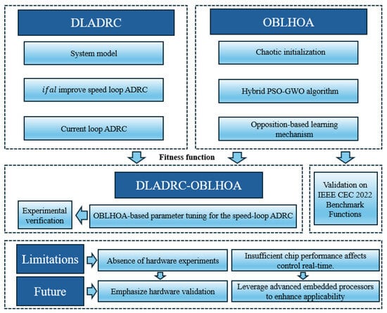
Figure 1.
Technical roadmap.
- (1)
- This paper proposes a dual-loop ADRC control strategy. First, in response to the poor smoothing of the nonlinear function in ADRC near the origin and breakpoint, a novel nonlinear function is designed to improve the speed-loop ADRC. Then, to eliminate the high-frequency oscillations caused by the improved nonlinear function, ADRC is introduced in the current loop.
- (2)
- A hybrid optimization algorithm based on opposition-based learning is proposed. Building upon a PSO-GWO hybrid algorithm, the method incorporates chaotic mapping and opposition-based learning mechanisms. Its effectiveness is validated through benchmark test functions and application to PMSM parameter tuning.
- (3)
- This paper presents a dual-loop ADRC control strategy for PMSM drives, implementing both speed and current loops in a coordinated dual-loop structure. Its practical application is currently constrained by limited computational resources. However, with the ongoing advancement of high-performance embedded processors and parallel computing platforms, these real-time limitations are gradually alleviated, making the implementation of dual-loop control feasible in practical industrial and vehicle drive applications.
The structure of this study is as follows: Section 1 provides the introduction. Section 2 presents the mathematical model of the PMSM and the ADRC model. Section 3 introduces a dual-loop ADRC control strategy (DLADRC). Section 4 details several classic heuristic algorithms and the proposed optimization algorithm OBLHOA. Section 5 presents the simulation results and analysis, and Section 6 concludes the paper.
2. Mathematical Modeling for PMSM and ADRC Principle
2.1. PMSM Mathematical Model
In the PMSM control system, an accurate mathematical model is the basis for realizing a high-performance speed control strategy, while the PMSM is a typical strongly coupled, multivariable, and nonlinear system whose dynamic behavior is affected by the electromagnetic coupling relationship, the mechanical structure characteristics, and the external perturbations. In order to deeply characterize its operation mechanism and provide theoretical support for the design of the improved ADRC strategy, this paper first derives the electromagnetic model of the PMSM under the rotating reference frame, which characterizes the dynamic interactions between stator electrical variables and electromagnetic torque. The voltage equation is expressed as follows:
where , , , , , represent direct and quadrature axial components in PMSM stator voltages, stator currents, and stator flux under two-phase rotation coordinate system and is the rotation angle of the rotor flux.
The stator flux is calculated as follows:
where and are the direct and quadrature axial inductances; is the flux linkage. For a surface-mounted PMSM, the electromagnetic torque equation can be expressed as follows because :
where represents the number of pole pairs.
The equation of motion is expressed as follows:
where J represents the moment of inertia, represents the motor velocity, represents the load torque, and B represents the coefficient of viscous friction.
Equation (5) can be obtained according to Equations (3) and (4):
Let ; then the state equation of the PMSM speed loop is obtained:
However, in practical applications, PMSM speed control involves multi-objective, multi-variable, and strongly nonlinear characteristics, making it difficult to fully describe the motor’s transient behavior using only mathematical models and physical formulas. Especially under conditions such as low-speed startup, high-speed operation, or sudden load changes, discrepancies between ideal simulation conditions and real experimental environments—such as motor nonlinearities, mechanical friction, vibrations, and external disturbances—may cause deviations in system response, affecting speed tracking accuracy and overall stability. In addition, practical hardware limitations, including sensor noise, sampling delays, and controller computation delays, further complicate precise control. Against this backdrop, achieving high-precision and robust speed control, while ensuring motor safety and performance stability in experiments, necessitates the adoption of advanced control methods with higher computational and real-time response requirements.
2.2. Design of the Active Disturbance Rejection Controller
The main components of the ADRC include the tracking differentiator (TD), the expansion state observer (ESO), and the nonlinear state error feedback rate (NLSEF). According to Equation (6), this is a second-order system. As a result, the speed loop in this case adopts second-order nonlinear ADRC. The structure of the ADRC is shown in Figure 2.

Figure 2.
ADRC structure diagram.
(1) The first component of the ADRC controller is the TD. The primary function of the TD is to preprocess the input signal. By enforcing a predefined transition process, the TD generates a smoothed version of the input along with its differential signal, effectively attenuating high-frequency noise and providing a reliable reference trajectory for the controller.
The TD can be described mathematically as
where r and are the parameters to be adjusted; h is the controller step size; k is the number of samples; is the first-order tracking differential signal of the input signal at time k; is the first-order differential signal of ; is a symbolic function.
(2) As a fundamental element of the ADRC architecture, the Extended State Observer (ESO) is designed to dynamically estimate both the internal system states and aggregated disturbances, including model uncertainties and external interferences. It utilizes a higher-order observer formulation to reconstruct the overall disturbance and enables real-time compensation within the control loop. This enables the control system to achieve so-called “active disturbance rejection”, wherein it autonomously adjusts to and mitigates the effects of external perturbations and model inaccuracies.
The mathematical expression for the ESO is
where is the filtering factor; , , are the state variable at time k; , , are the observed coefficient; e is the error term; is the actual speed of the motor at time k; , , are the coefficient associated with the estimation error.
(3) The primary function of NLSEF is to automatically compensate for system perturbations by providing non-linear feedback on the system’s state error, thereby reducing system error and increasing system robustness.
The mathematical expression for NLSEF is
where is the error feedback control quantity at time k; , are the gain factor.
where is the output of ADRC at time k; is the compensation factor.
3. Design of ADRC System for PMSM
3.1. Design of Speed-Loop ADRC
According to Equation (9), the function has bad smoothness near the origin and discontinuity points, so this paper designs a new non-linear function, , and uses it to improve the ESO. Compared with the traditional function, the function has better derivability, continuity, and smoothness near the origin.
The expression for is as follows:
where , , are the function coefficient; to avoid excessive gain under large error conditions, saturation is applied to both ends of the function when .
When , the function is required to be both differentiable and continuous. Therefore, the following condition must be satisfied:
Combining Equations (13) and (14), we obtain
By solving Equation (15), the values of , and can be obtained.
As shown in Figure 3, the product of the function and the error is greater than or equal to 0, with a value of 0 at the origin. Moreover, the function exhibits improved continuity and smoothness in the vicinity of the origin; hence, it meets the design requirements for a nonlinear function. On this basis, the mathematical expression for the improved ESO is
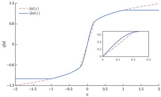
Figure 3.
Comparison of nonlinear functions.
The function is compared with the function as shown in Figure 3.
The mathematical expression for the improved NLSEF is
3.2. Design of Current-Loop ADRC
Although the improved function significantly enhances the response speed and disturbance rejection capability of the ADRC, its relatively large gain in the small-error region leads to an excessive response of the current loop to minor disturbances, resulting in high-frequency oscillations. The PI controller in the current loop has limited bandwidth and disturbance suppression capabilities, making it unable to respond quickly to these high-frequency fluctuations. Therefore, to reduce steady-state current ripple and high-frequency speed fluctuations, an active disturbance rejection controller is introduced into the current loop.
When the control approach is applied, the following can be obtained according to Equations (1) and (2):
In the vector control of PMSM, current regulation is influenced by factors such as resistance, inductance, flux linkage, as well as various system uncertainties and external disturbances. The following represents the total disturbance on the axis:
Let , ; the state equation of the axis current can be derived by combining Equations (19) and (20):
Therefore, the first-order ADRC of the current loop can be constructed and the first-order ADRC block diagram is shown in Figure 4.
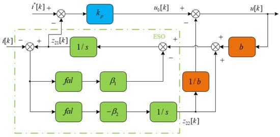
Figure 4.
Block diagram of current loop first-order ADRC.
The expressions for the current-loop ADRC are given below.
where , are the error signal; is the actual current of the axis at time k; is the rated current of the axis at time k; is the tracking signal of the system output (actual current) at time k; is the estimated signal of the total system perturbation at time k; , are the gain coefficient; b is the compensation factor. Both the d axis and q axis current control loops are implemented using an identical control structure.
Remark 1.
The simulation model proposed in this paper is based on idealized conditions and does not account for practical hardware limitations, such as measurement errors, sensor inaccuracies, or noise in the feedback signals. In real applications, these factors may lead to deviations in system response and could pose safety risks during hardware experiments, such as overcurrent, overheating, or demagnetization of the motor, potentially causing damage to the equipment.
Remark 2.
In this simulation study, no advance control beats (advance control beats = 0) or auxiliary torque loop (as introduced in [22]) are applied. This is because, under ideal simulation conditions, there is no hardware delay or inertia-induced lag, and the system can respond instantaneously to reference commands. In contrast, hardware experiments such as [22] employed a one-beat advance actuation together with a torque loop to compensate for response delay and reduce overshoot. Such measures are unnecessary in the present simulation environment, where the purpose is to evaluate the inherent performance of the proposed control strategy.
Remark 3.
Under the simulation conditions, both the control period and the sampling period are 0.1 ms, which is much shorter than the PWM period in practical hardware. Therefore, the dynamic response constraints of “5 current PWM periods and 10 speed PWM periods” are no longer applicable. These constraints are primarily imposed due to the limited computational capability and sampling period in hardware, whereas in the simulation environment, the controller’s computation and signal acquisition are nearly instantaneous.
In summary, according to Remarks 1, 2 and 3, the general block diagram of the DLADRC speed control of PMSM is in Figure 5.
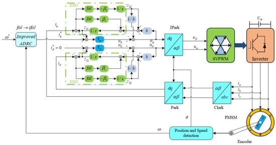
Figure 5.
Overall block diagram of PMSM speed control.
3.3. Optimization of Control Parameters
The speed-loop ADRC designed in this paper has 16 parameters to be optimized as shown in (24).
The current-loop ADRC has four parameters to be optimized as shown in (25).
In this study, an improved optimization algorithm is used to tune five key parameters, while others are set empirically. To evaluate control performance, the Integral of Time-Weighted Absolute Error (ITAE) is adopted as the objective function due to its sensitivity to transient response and dynamic behavior. This makes it well-suited for PMSM systems with rapid response and frequent load changes. The mathematical expression of ITAE is as follows:
In conclusion, the proposed OBLHOA algorithm is integrated into the PMSM control system to optimize the parameters of the speed-loop ADRC, thereby enhancing overall control performance. The optimization process is shown in Figure 6:
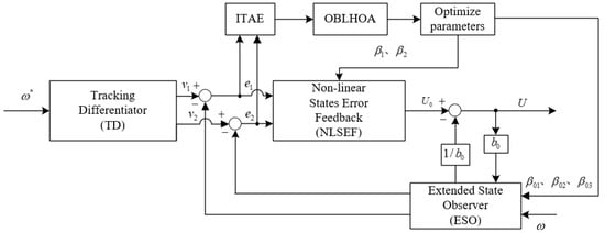
Figure 6.
Block diagram of speed-loop ADRC parameter optimization.
4. Design of Opposition-Based Learning Hybrid Optimization Algorithm
4.1. Particle Swarm Optimization (PSO)
Particle swarm optimization (PSO) is a heuristic optimization technique that simulates social behavior in nature, where individuals adjust their trajectories based on both self-evaluation and group knowledge [23]. In PSO, the candidate solutions of the problem are abstracted as particles, each of which has two basic properties, position and velocity, in the search space. By simulating the information sharing and co-evolution mechanism among individuals in the population, the particles continuously move iteratively in the search space. During the search process, each particle retains its own optimal position (individual optimal), and at the same time obtains the current optimal position (global optimal) of the whole group as the basis for learning so that it can adjust its speed and position in real time, thereby realizing the integration of individual experience and group knowledge. Through this mechanism, the swarm of particles can collaborate in the search space and gradually approach the global optimal solution. In each iteration, particle velocity and position are modified based on the equations below.
where and represent the current position and velocity of particle i at the t-th iteration, respectively; is the currently recorded individual historical optimal position of particle i; is the personal best position recorded by particle i up to the current iteration; is the inertia weights; and are learning factors, , ; and are random numbers between 0 and 1 used to increase the randomness of the search.
4.2. Gray Wolf Optimizer (GWO)
The gray wolf optimizer (GWO) models the social hierarchy and group hunting strategies of gray wolves to guide the search process, and it has shown strong potential in handling a wide range of challenging optimization tasks [24]. In nature, gray wolves typically hunt in groups and exhibit a distinct social hierarchy: the wolf serves as the leader responsible for decision-making; the wolf acts as a subordinate leader assisting the and potentially replacing it; the wolf occupies the third tier, responsible for communication and coordination within the pack; and the remaining wolves are categorized as , which are subordinate and follow the guidance of higher-ranking members. The GWO emulates this hierarchical model in optimization by designating the top three candidates in the population as , , and wolves, which collaboratively guide the remaining candidates ( wolves) toward the global optimum in the solution space.
The optimization process in the GWO mimics the natural hunting mechanism of gray wolves and consists of three primary phases: encircling the prey, hunting, and attacking. During the encircling phase, gray wolves update their positions to converge toward the location of the prey according to the following mathematical model.
where is the position of the prey (the optimal solution), is the current position of the wolf, and is the distance vector. The vectors and are the moderators, defined as follows:
where is the linear decreasing factor, decreasing from 2 to 0 (as the number of iterations increases) and used to regulate the ratio of global search to local exploitation; , are the random vector uniformly distributed in the interval [0, 1].
During the tracking phase, the GWO assumes that the , and individuals possess the most accurate estimations of the prey’s potential location. Accordingly, the remaining individuals in the population update their positions by simultaneously referencing these three leaders:
The final position update formula is as follows.
This mechanism realizes the joint decision making of multiple leading individuals; Hence, it effectively improves the diversity of search directions and avoids falling into local optimality. As the iteration progresses, the decrease in makes the range of narrow from [−2, 2] to [0, 0], thus realizing the natural transition from global exploration to local exploitation.
4.3. Opposition-Based Learning Hybrid Optimization Algorithm (OBLHOA)
4.3.1. Logistic Chaotic Mapping Mechanism
Chaotic motion is a typical nonlinear dynamic phenomenon characterized by ergodicity, randomness, and sensitivity to initial conditions. In the process of algorithmic optimization, when the population becomes trapped in local optima or the search stagnates, introducing a chaotic mechanism can effectively enhance global search capability and increase the likelihood of escaping from local extrema. Among various chaotic maps, the Logistic map is a classical and structurally simple one-dimensional chaotic system, which is mathematically expressed as
where , and the parameter is a constant, which is typically assigned a value of 4.
The chaotic map is introduced into the population position initialization process. The initial positions of individuals can be generated using the chaotic sequence, which is defined as
where and are the lower and upper bounds of the j-th dimensional variable, respectively.
4.3.2. Opposition-Based Learning Mechanism
Opposition-based learning (OBL) is a novel optimization strategy proposed by Tizhoosh in 2005 [25]. Its core idea is to consider both the current solution and its corresponding opposite solution during the search process, evaluate the fitness of the two, and retain them in a preferential manner, leading to more efficient exploration and improved solution performance. To further improve its ability to locate the global optimum, this paper introduces the opposition-based learning mechanism into the improved optimization framework to more effectively guide the individuals to accelerate convergence towards the optimal solution.
The computation of the opposite solution is based on the symmetric mapping of the current solution in the search space, and for the given solution , its opposite solution is computed as
To further enhance the optimization performance of the algorithm, the OBL strategy is incorporated with a probability of 0.15. When the OBL strategy is activated, only 10% of the particles are selected, including the one with the best fitness, to perform opposition-based learning.
Specifically, when , 10% of the particles are randomly selected along with the globally best particle to undergo opposition-based learning according to Equation (36). Otherwise, the OBL strategy is not applied.
This mechanism facilitates faster exploration of the search space during the early stages of optimization and enables more stable local exploitation once potential optima are found, thereby improving both the solution accuracy and convergence speed.
4.3.3. Process Design of the OBLHOA
Based on the analysis presented in the preceding sections, both PSO and the GWO exhibit unique advantages. PSO is widely employed in solving optimization problems due to its strong global search capability and fast convergence speed. However, during the search for the global optimum, PSO guides some particles to randomly explore regions that may help avoid local optima; meanwhile, it can inadvertently cause the algorithm to become trapped in local minima. By combining the PSO with the GWO, certain particles can be guided to more promising areas optimized by the GWO, thereby effectively reducing the risk of falling into local optima and premature convergence.
The proposed OBLHOA algorithm primarily relies on the fundamental search mechanism of PSO. To enhance the global exploration capability during the early stages of the optimization process, the GWO update mechanism is activated during the first 30% of the total iterations. The triggering condition can be expressed as follows:
When this condition is met, 30% of the population is randomly selected to undergo position updates according to the GWO strategy, thereby improving the algorithm’s diversity and its ability to escape local optima.
The improved OBLHOA algorithm primarily employs PSO as its core search mechanism. To enhance global exploration during the early stages, the GWO update strategy is activated for 30% of the total iterations. Within this phase, 30% of the population is randomly selected at each iteration to undergo position updates guided by the GWO, which increases population diversity and improves the ability to escape local optima. The population initialization is performed via logistic chaotic mapping to ensure a more uniform distribution. Additionally, an opposition-based learning strategy with a defined probability is incorporated to further expand the search space and maintain diversity, effectively preventing premature convergence and improving solution accuracy. The detailed flowchart of the proposed OBLHOA algorithm is illustrated in Figure 7.
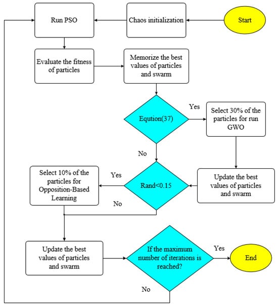
Figure 7.
OBLHOA flowchart.
5. Simulation Results and Analysis
5.1. Discussion and Analysis of Algorithm Performance
To verify the optimization performance of the proposed OBLHOA algorithm, comparison experiments were conducted on the IEEE CEC 2022 benchmark function set with the classical algorithms PSO, GWO, and SSA. Table 2 lists the mean and standard deviation (Std) of the best values obtained by each algorithm on 12 typical benchmark functions (F1–F12) to evaluate the accuracy and stability of the algorithms. All benchmark functions are tested in a 10-dimensional search space.

Table 2.
Comparison of PSO, GWO, SSA, and OBLHOA on benchmark functions.
The experimental results fully validate the superior performance of the proposed OBLHOA algorithm on the CEC 2022 benchmark test functions. Specifically, for unimodal functions (F1), OBLHOA accurately converges to the theoretical optimum with the lowest standard deviation, demonstrating strong stability and convergence precision during the local search phase. For multimodal functions (F2–F5), OBLHOA significantly outperforms other algorithms by effectively avoiding local optima, reflecting its strong global search capability and efficient exploration of the solution space. On hybrid functions (F6–F8), OBLHOA generally achieves better mean best values than comparison algorithms while maintaining low standard deviations, indicating better convergence quality and robustness in complex search spaces. Particularly on composition functions (F9–F12), OBLHOA attains optimal performance in multiple test cases, showing strong adaptability and broad generalization ability.
5.2. Discussion and Analysis of DLADRC Performance
The proposed PMSM speed control model with dual-loop ADRC based on OBLHOA is implemented on the MATLAB 2022b/Simulink platform. The system runs on Windows 10 with an AMD Ryzen 5 4600H processor with Radeon Graphics @ 3.00 GHz. Parameters of the PMSM model are shown in Table 3 [26], parameters of DLADRC, and initialization range of parameters to be adjusted are shown in Table 4 and Table 5. The detailed parameters of the PI controller and classical ADRC used in the comparative experiments are shown in Table 6 and Table 7.

Table 3.
Key parameters of permanent magnet synchronous motor.

Table 4.
DLADRC empirical parameters.

Table 5.
Initialization range of parameters to be adjusted.

Table 6.
PI controller parameters.

Table 7.
Classical ADRC parameters.
To comprehensively assess the performance of the proposed control strategy, three representative driving conditions commonly encountered in electric vehicles are simulated as test cases. The proposed method is then compared with traditional PI and classical ADRC controllers. The parameters of both the PI and ADRC controllers are tuned based on empirical methods and iterative experimental adjustments. Since the rated current in Table 3 is 6.7 A, current limiting is applied to all controllers in the simulations, restricting the maximum current to 13 A to ensure a fair and realistic comparison. Experiment 1 simulates an electric vehicle operating at low speed in an urban environment and decelerating due to external disturbances, such as road inclines or increased resistance. Specifically, the initial motor speed is set to 1000 rpm, a load torque of 5 Nm is applied at 0.2 s, and the reference speed is decreased to 800 rpm at 0.4 s. Experiment 2 represents a scenario in which the electric vehicle accelerates due to overtaking, changing road conditions, or driver-initiated acceleration based on traffic flow and then returns to normal cruising speed. The motor speed is initially set to 1000 rpm, increases to 1200 rpm at 0.2 s, and then returns to 1000 rpm at 0.4 s. Experiment 3 simulates continuous load variation during a speed transition process. The motor starts at 1000 rpm with a sudden application of 5 Nm load torque at 0.15 s; at 0.3 s, the reference speed is increased to 1200 rpm; and at 0.4 s, the load torque is further increased from 5 Nm to 10 Nm. These scenarios are designed to reflect representative electric vehicle operating conditions and provide a basis for evaluating the robustness and dynamic performance of the proposed control strategy.
To clearly demonstrate the advantage of the proposed OBLHOA algorithm over traditional heuristic algorithms in motor parameter tuning, the OBLHOA, PSO, GWO and SSA algorithms are employed to optimize the parameters of the DLADRC under the first experimental scenario. Given that the differences among the three PMSM control scenarios are relatively small, the key speed ADRC parameters obtained from the first scenario are also applicable to the other two scenarios. For the OBLHOA algorithm, the parameter settings are as follows: the population size is 50, the maximum number of iterations is 100, and the dimensionality is 5. The initialization ranges of the parameters to be optimized are presented in Table 5, and the optimized parameters obtained through the algorithm are listed in Table 8.

Table 8.
Parameter values after optimization by algorithm.
According to the simulation results presented in Figure 8, the average convergence behavior of PSO, GWO, SSA, and OBLHOA can be observed. It is evident from Figure 8 that all four algorithms successfully achieve convergence. In particular, OBLHOA demonstrates the fastest convergence rate and ultimately attains the best optimization result. This indicates that OBLHOA outperforms PSO, GWO, and SSA in both convergence speed and optimization effectiveness. Furthermore, the graph shows that OBLHOA approaches its final optimal value after approximately 20 iterations, while PSO, GWO, and SSA require more iterations to reach a similar level of convergence. These findings further confirm the effectiveness and superiority of the proposed algorithm.
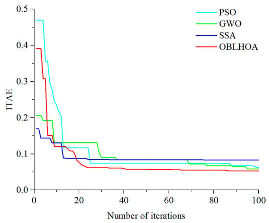
Figure 8.
Comparison of iteration curves of four algorithms.
To evaluate the effectiveness of the current-loop ADRC, a comparative study was conducted under the conditions of Scenario 1 between the speed control system equipped with the current-loop ADRC and the system without it.
In Figure 9 and Figure 10, “ADRC-ifal” denotes the speed-loop ADRC with only the improved IFAL function, without the incorporation of the current-loop ADRC. As shown in Figure 9, when the current-loop ADRC is not introduced, the rotor speed exhibits high-frequency oscillations with an amplitude of approximately 0.5 rpm/min. After introducing the current-loop ADRC, these speed fluctuations become negligible. Figure 10 shows that, without the current-loop ADRC, the torque fluctuates with an amplitude of 1.4 Nm, whereas the introduction of the current-loop ADRC significantly reduces the torque fluctuations to about 0.15 Nm. In summary, the inclusion of the current-loop ADRC effectively suppresses high-frequency oscillations in both speed and torque, thereby significantly improving the system’s stability and dynamic response performance.
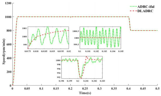
Figure 9.
Comparison of speed response with and without current-loop ADRC.
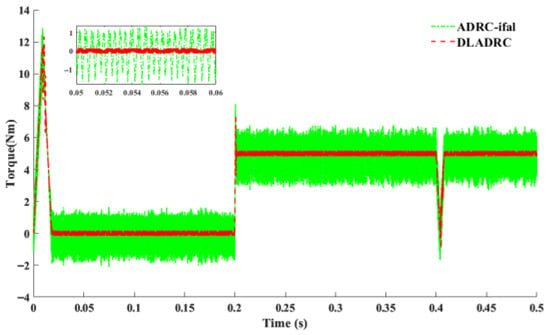
Figure 10.
Comparison of torque response with and without current-loop ADRC.
The speed and torque curves of PMSM under the three control strategies of PI, ADRC, and DLADRC-OBLHOA for three experimental scenarios are shown below.
As illustrated in Figure 11, the proposed DLADRC-OBLHOA strategy demonstrates superior dynamic performance compared to both PI and classical ADRC controllers in Experiment 1. Specifically, the DLADRC-OBLHOA achieves the rated speed in approximately 0.018 s with no significant overshooting, and the convergence rate is fast and stable. In contrast, the PI controller reaches the rated speed in 0.12 s and exhibits a notable overshoot of 12.9%, while the ADRC controller reaches the rated speed in 0.028 s without overshoot. Following the application of a sudden load torque disturbance of 5 Nm, the DLADRC-OBLHOA exhibits the highest disturbance rejection capability, with a minimal speed drop of only 8.5 r/min and the fastest recovery time of 0.00129 s. Comparatively, the PI controller undergoes a substantial speed drop of 65 r/min and requires 0.1 s to return to the rated speed, while the ADRC experiences a speed drop of 8.6 r/min and recovers in 0.005 s. During the deceleration phase, the DLADRC-OBLHOA brings the speed down to 800 r/min and reaches a steady state in just 0.008 s, thereby outperforming both the PI controller (0.05 s) and the classical ADRC (0.0125 s).
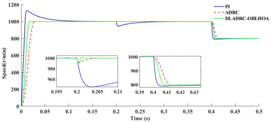
Figure 11.
Comparison of speed for Experiment 1 scenario.
As illustrated in Figure 12, under Scenario 2, when the PMSM accelerates from the rated speed to 1200 rpm, the proposed DLADRC-OBLHOA exhibits the fastest convergence to steady state, with a settling time of approximately 0.008 s and zero overshoot. In contrast, the PI controller reaches steady state in 0.06 s with an overshoot of 0.91%, while the ADRC achieves stabilization in 0.0125 s without overshoot. Similarly, during the deceleration phase from 1200 rpm back to 1000 rpm, the DLADRC-OBLHOA again demonstrates the shortest settling time of 0.008 s and non-overshooting behavior. The PI controller requires 0.06 s and exhibits an overshoot of 1%, whereas the ADRC settles in 0.0125 s with no overshoot.
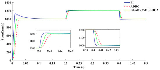
Figure 12.
Comparison of speed for Experiment 2 scenario.
As shown in Figure 13, under Scenario 3, when the load torque is suddenly increased from 5 Nm to 10 Nm at 0.4 s, the speed drop under DLADRC-OBLHOA control is approximately 12.7 r/min, and the system recovers to steady state within approximately 0.0023 s. In contrast, the ADRC exhibits a speed drop of about 14 r/min with a recovery time of approximately 0.005 s, while the PI controller experiences a much larger speed drop of around 56 r/min and requires about 0.1 s to regain steady state.
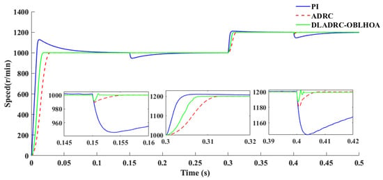
Figure 13.
Comparison of speed for Experiment 3 scenario.
Figure 14, Figure 15 and Figure 16 illustrate the torque responses and fluctuations under different control strategies. The measured steady-state torque ripples are approximately 0.25 Nm for PI control, 0.5 Nm for ADRC, and 0.15 Nm for DLADRC-OBLHOA. In all scenarios, the PI controller produces the largest overshoot at start-up and is highly sensitive to disturbances, which leads to sharp torque spikes and poor robustness. The conventional ADRC provides noticeable improvement in the transient response, with smaller overshoot and faster convergence compared to PI; however, its steady-state torque is affected by evident high-frequency oscillations, as clearly shown in the zoomed-in insets. By contrast, the proposed DLADRC-OBLHOA not only achieves a lower overshoot than both PI and ADRC but also stabilizes more quickly and maintains smooth torque with minimal oscillations. Furthermore, under disturbance conditions, DLADRC-OBLHOA exhibits rapid recovery capability and ensures stable torque output. These results comprehensively demonstrate that PI control is prone to severe overshoot, ADRC reduces overshoot but struggles with steady-state fluctuations, while DLADRC-OBLHOA combines fast dynamic response, strong disturbance rejection, and excellent steady-state performance, thereby highlighting its superior control effectiveness.
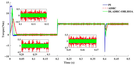
Figure 14.
Comparison of torque for experiment 1 scenario.
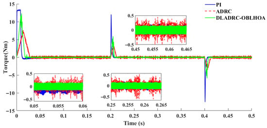
Figure 15.
Comparison of torque for Experiment 2 scenario.
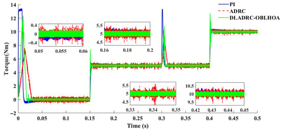
Figure 16.
Comparison of torque for Experiment 3 scenario.
In addition, it is expected that the advantages of DLADRC-OBLHOA in startup speed, disturbance rejection, and torque stability can be verified in practical hardware experiments. However, due to factors such as measurement noise, sensor inaccuracies, limited sampling rates, and controller computation delays in real hardware, the observed performance may be slightly lower than in simulations. Nevertheless, the experimental results are still expected to demonstrate clear improvements of DLADRC-OBLHOA over conventional PI and standard ADRC controllers in terms of dynamic response, disturbance rejection, and speed/torque stability.
In summary, these comparative results clearly demonstrate that the PI controller has the poorest performance in terms of response speed and disturbance rejection. Compared to ADRC, the proposed DLADRC-OBLHOA achieves faster no-load startup, smaller speed deviation under sudden load application, shorter recovery time, and faster transition back to steady state. Furthermore, when the PMSM operates in steady state, DLADRC-OBLHOA achieves significantly better torque stability, reducing torque fluctuations by 0.1 Nm and 0.35 Nm compared to PI and ADRC, respectively. In summary, the proposed DLADRC-OBLHOA provides superior dynamic response, enhanced disturbance rejection, and improved speed and torque stability for PMSM operation. It should be noted, however, that this study is limited to simulation conditions, and the cost-effectiveness and practical benefits of implementing this approach in hardware experiments remain uncertain.
6. Conclusions
This paper proposes a dual-loop ADRC (DLADRC) strategy, in which an opposition-based learning hybrid optimization algorithm (OBLHOA) is employed to enhance the speed regulation performance of the PMSM. A new nonlinear function, , is designed to improve the smoothness of ESO estimation near the origin and breakpoint. In addition, a current loop based on ADRC is introduced to stabilize motor torque control. To address the challenge of ADRC parameter tuning, OBLHOA is developed by integrating PSO with the GWO, incorporating chaotic mapping for initialization and opposition-based learning to expand the search space and prevent premature convergence. Experimental results show that OBLHOA outperforms conventional heuristic algorithms in terms of optimization performance. The proposed DLADRC-OBLHOA controller also demonstrates superior convergence speed, accuracy, and robustness compared to PI and classical ADRC across four complex operating scenarios.
Despite the favorable simulation results of the proposed dual-loop ADRC strategy, several limitations remain in this study.
- (I)
- The present work is restricted to the simulation stage, without hardware experiments or hardware-in-the-loop (HIL) validation. The idealized simulation environment does not capture practical effects such as ADC delays, PWM dead zones, sampling noise, and other non-idealities. Consequently, the real-world performance and robustness of the proposed controller remain unverified.
- (II)
- When applying the current simulation model to hardware experiments, the computational resources and real-time capability of the embedded processor must be carefully considered, as complex control laws may be constrained by limited chip performance.
- (III)
- The current-loop ADRC design is relatively basic, lacking systematic parameter optimization and accurate system modeling, which may restrict its effectiveness in low-level torque control.
- (IV)
- The optimization algorithm is implemented offline, without accounting for real-time constraints, which reduces its applicability under dynamic or uncertain operating conditions.
Based on the above limitations, future research directions can be outlined as follows:
- (I)
- Future research may explore conducting hardware experiments and hardware-in-the-loop (HIL) testing to further evaluate the practical performance, robustness, and reliability of the proposed controller under real-world non-ideal conditions. The experimental platform could be upgraded from the TMS320F28335 to the MPC555LFMZP40, enabling an investigation into the feasibility of extending the control period to 35–40 ms. Moreover, project funding may support the acquisition of higher-performance Siemens motors, which would help advance research in this direction. These potential developments could lead to further publications in this esteemed journal.
- (II)
- With the continuous improvement of embedded processor performance and the relaxation of control-cycle constraints, the real-time implementation of complex control algorithms will become increasingly feasible, enabling the proposed approach to be applied in practical systems.
- (III)
- Enhance the current-loop ADRC design through systematic parameter tuning and accurate modeling techniques to improve its torque control performance.
- (IV)
- Develop online or adaptive optimization frameworks—such as reinforcement learning or hybrid intelligent algorithms—to achieve real-time parameter tuning and adaptation under dynamic and uncertain environments.
Author Contributions
The study was jointly conducted by all participating authors. Z.W. was responsible for the experimental research and wrote the manuscript. L.W., as Z.W.’s advisor, provided project support and guidance in manuscript writing and revision but was not involved in the simulation experiments or parameter settings. Y.L. provided learning materials and experimental equipment. Y.C. translated and polished the manuscript. Z.W. is the student corresponding author of this manuscript, and Y.C. is the corresponding author of the manuscript. All authors have read and agreed to the published version of the manuscript.
Funding
This research was funded by the Liaoning Provincial Department of Transportation Scientific Research Project (202344, 202417), the Liaoning Provincial Department of Education Scientific Research Project (JYTMS20230038), the Dalian Universities Teaching and Scientific Research Ability Improvement for Excellent Young Teachers’ Project (0320A2418), the Chizhou University Nature Key Project (CZ2022ZRZ08), and the Chizhou University Nature Transverse Project (2025HX0095, 2024HX0044, 2023HX0060).
Data Availability Statement
The simulation data generated during this study are included in the main article. The external benchmark data used in this work are the IEEE CEC 2022 test suite, which is publicly available from the IEEE CEC benchmark repository.
Acknowledgments
This work gratefully acknowledges the support of the Liaoning Provincial Department of Transportation Scientific Research Project (202344, 202417), the Liaoning Provincial Department of Education Scientific Research Project (JYTMS20230038), the Dalian Universities Teaching and Scientific Research Ability Improvement for Excellent Young Teachers’ Project (0320A2418), the Chizhou University Nature Key Project (CZ2022ZRZ08), and the Chizhou University Nature Transverse Project (2025HX0095, 2024HX0044, 2023HX0060).
Conflicts of Interest
The authors declare no conflicts of interest.
Correction Statement
This article has been republished with a minor correction to the Data Availability Statement. This change does not affect the scientific content of the article.
Abbreviations
The following abbreviations are used in this manuscript:
| IADRC | improved active disturbance rejection controller |
| OBLHOA | opposition-based learning hybrid optimization algorithm |
| PSO | particle swarm optimization |
| GWO | gray wolf optimization |
| SMC | sliding-mode control |
| MPC | model predictive control |
| TD | tracking differentiator |
| ESO | expansion state observer |
| NLSEF | nonlinear state error feedback |
| SSA | sparrow search algorithm |
References
- Liu, J.; Li, H.; Deng, Y. Torque ripple minimization of PMSM based on robust ILC via adaptive sliding mode control. IEEE Trans. Power Electron. 2017, 33, 3655–3671. [Google Scholar] [CrossRef]
- Sun, Z.; Deng, Y.; Wang, J.; Yang, T.; Wei, Z.; Cao, H. Finite control set model-free predictive current control of PMSM with two voltage vectors based on ultralocal model. IEEE Trans. Power Electron. 2022, 38, 776–788. [Google Scholar] [CrossRef]
- Cao, H.; Deng, Y.; Li, H.; Wang, J.; Liu, X.; Sun, Z.; Yang, T. Generalized active disturbance rejection with reduced-order vector resonant control for PMSM current disturbances suppression. IEEE Trans. Power Electron. 2023, 38, 6407–6421. [Google Scholar] [CrossRef]
- Liang, D.; Li, J.; Qu, R.; Kong, W. Adaptive second-order sliding-mode observer for PMSM sensorless control considering VSI non-linearity. IEEE Trans. Power Electron. 2017, 33, 8994–9004. [Google Scholar] [CrossRef]
- Deng, Y.; Wang, J.; Li, H.; Liu, J.; Tian, D. Adaptive sliding mode current control with sliding mode disturbance observer for PMSM drives. ISA Trans. 2019, 88, 113–126. [Google Scholar] [CrossRef]
- Jingqing, H. Auto-disturbances-rejection controller and its applications. Control Decis. 1998, 13, 19–23. [Google Scholar]
- Jabbour, N.; Mademlis, C. Online parameters estimation and autotuning of a discrete-time model predictive speed controller for induction motor drives. IEEE Trans. Power Electron. 2018, 34, 1548–1559. [Google Scholar] [CrossRef]
- Han, J. From PID to active disturbance rejection control. IEEE Trans. Ind. Electron. 2009, 56, 900–906. [Google Scholar] [CrossRef]
- Cui, Y.; Yin, Z.; Cao, X.; Zhang, Y.; Liu, Y. Enhanced Linear Active Disturbance Rejection Speed Control of IPMSM Based on Interference Differential Compensation and Cascaded Linear Extended State Observer. IEEE Trans. Power Electron. 2024, 39, 13582–13596. [Google Scholar] [CrossRef]
- Chang, X.; Jin, C.; Cheng, Y. Dynamics and advanced active disturbance rejection control of tethered UAV. Appl. Math. Model. 2024, 135, 640–665. [Google Scholar] [CrossRef]
- Lin, P.; Wu, Z.; Liu, K.Z.; Sun, X.M. A class of linear–non-linear switching active disturbance rejection speed and current controllers for PMSM. IEEE Trans. Power Electron. 2021, 36, 14366–14382. [Google Scholar] [CrossRef]
- Liu, X.; Deng, Y.; Wang, J.; Li, H.; Cao, H. Fixed-time generalized active disturbance rejection with quasi-resonant control for PMSM speed disturbances suppression. IEEE Trans. Power Electron. 2024, 6, 6903–6918. [Google Scholar] [CrossRef]
- Liu, Y.C.; Laghrouche, S.; Depernet, D.; N’Diaye, A.; Djerdir, A.; Cirrincione, M. Disturbance-observer-based speed control for SPMSM drives using modified super-twisting algorithm and extended state observer. Asian J. Control 2024, 26, 1089–1102. [Google Scholar] [CrossRef]
- Dang, C.; Dou, M.; Yan, S.; Dang, M.; Wang, Y.; Zhao, D.; Hua, Z. An Improved Adaptive Sliding Mode Speed Control of PMSM Drives With an Extended State Observer. IEEE Trans. Energy Convers. 2024, 39, 2349–2361. [Google Scholar] [CrossRef]
- Huang, M.; Ma, Y.; Wan, J.; Chen, X. A Sensor-Software Based on a Genetic Algorithm-Based Neural Fuzzy System for Modeling and Simulating a Wastewater Treatment Process. Appl. Soft Comput. 2015, 27, 1–10. [Google Scholar] [CrossRef]
- Jin, H.; Chen, X.; Wang, L.; Yang, K.; Wu, L. Adaptive soft sensor development based on online ensemble Gaussian process regression for non-linear time-varying batch processes. Ind. Eng. Chem. Res. 2015, 54, 7320–7345. [Google Scholar] [CrossRef]
- Pisa, I.; Santin, I.; Morell, A.; Vicario, J.L.; Vilanova, R. LSTM-based wastewater treatment plants operation strategies for effluent quality improvement. IEEE Access 2019, 7, 159773–159786. [Google Scholar] [CrossRef]
- Yang, X.; Huang, Q.; Jing, S.; Zhang, M.; Zuo, Z.; Wang, S. Servo system control of satcom on the move based on improved ADRC controller. Energy Rep. 2022, 8, 1062–1070. [Google Scholar] [CrossRef]
- Oyewole, O.E.; Abdelaziz, A.A.; Jimoh, I.A.; Bari, E.; Ahmed, K.H. Optimised linear active disturbance rejection control of multiport-isolated DC-DC converter for hydrogen energy storage system integration. Alex. Eng. J. 2024, 102, 159–168. [Google Scholar] [CrossRef]
- Liang, S.; Guo, M.; Tian, Y.; Le, J.; Song, W. Research on intelligent active disturbance rejection control algorithm for shock train leading edge of dual-mode scramjet. Phys. Fluids 2024, 36, 015103. [Google Scholar] [CrossRef]
- Yang, Z.; Lu, C.; Sun, X.; Ji, J.; Ding, Q. Study on active disturbance rejection control of a bearingless induction motor based on an improved particle swarm optimization–genetic algorithm. IEEE Trans. Transp. Electrif. 2020, 7, 694–705. [Google Scholar] [CrossRef]
- Wang, L.; Liu, G.; Xu, C. An improved nonlinear active disturbance rejection controller via sine function and whale optimization algorithm for permanent magnet synchronous motors speed control. IEEJ Trans. Electr. Electron. Eng. 2025, 20, 694–705. [Google Scholar] [CrossRef]
- Kennedy, J.; Eberhart, R. Particle swarm optimization. In Proceedings of the ICNN’95-International Conference on Neural Networks, Perth, WA, Australia, 27 November–1 December 1995; Volume 4. [Google Scholar]
- Mirjalili, S.; Mirjalili, S.M.; Lewis, A. Gray wolf optimizer. Adv. Eng. Softw. 2014, 69, 46–61. [Google Scholar] [CrossRef]
- Mahdavi, S.; Rahnamayan, S.; Deb, K. Opposition based learning: A literature review. Swarm Evol. Comput. 2018, 39, 1–23. [Google Scholar] [CrossRef]
- Lei, Y. Principles of Modern Permanent Magnet Synchronous Motor Control and MATLAB Simulation; Publishing House of Electronics Industry: Beijing, China, 2016. [Google Scholar]
Disclaimer/Publisher’s Note: The statements, opinions and data contained in all publications are solely those of the individual author(s) and contributor(s) and not of MDPI and/or the editor(s). MDPI and/or the editor(s) disclaim responsibility for any injury to people or property resulting from any ideas, methods, instructions or products referred to in the content. |
© 2025 by the authors. Licensee MDPI, Basel, Switzerland. This article is an open access article distributed under the terms and conditions of the Creative Commons Attribution (CC BY) license (https://creativecommons.org/licenses/by/4.0/).