Article

Logical Execution Time and Time-Division Multiple Access in Multicore Embedded Systems: A Case Study

by
Carlos-Antonio Mosqueda-Arvizu
1,
Julio-Alejandro Romero-González
1,*,
Diana-Margarita Córdova-Esparza
1,
Juan Terven
2,
Ricardo Chaparro-Sánchez
1 and
Juvenal Rodríguez-Reséndiz
3
1
Faculty of Informatics, Autonomous University of Queretaro, Queretaro 76230, Mexico
2
CICATA-Queretaro Unit, National Polytechnic Institute, Cerro Blanco No. 141, Col. Colinas del Cimatario, Queretaro 76090, Mexico
3
Faculty of Engineering, Autonomous University of Queretaro, Queretaro 76010, Mexico
*
Author to whom correspondence should be addressed.
Algorithms 2024, 17(7), 294; https://doi.org/10.3390/a17070294
Submission received: 9 June 2024 / Revised: 1 July 2024 / Accepted: 3 July 2024 / Published: 5 July 2024
(This article belongs to the Special Issue Scheduling: Algorithms and Real-World Applications)

Abstract

:
The automotive industry has recently adopted multicore processors and microcontrollers to meet the requirements of new features, such as autonomous driving, and comply with the latest safety standards. However, inter-core communication poses a challenge in ensuring real-time requirements such as time determinism and low latencies. Concurrent access to shared buffers makes predicting the flow of data difficult, leading to decreased algorithm performance. This study explores the integration of Logical Execution Time (LET) and Time-Division Multiple Access (TDMA) models in multicore embedded systems to address the challenges in inter-core communication by synchronizing read/write operations across different cores, significantly reducing latency variability and improving system predictability and consistency. Experimental results demonstrate that this integrated approach eliminates data loss and maintains fixed operation rates, achieving a consistent latency of 11 ms. The LET-TDMA method reduces latency variability to approximately 1 ms, maintaining a maximum delay of 1.002 ms and a minimum delay of 1.001 ms, compared to the variability in the LET-only method, which ranged from 3.2846 ms to 8.9257 ms for different configurations.

1. Introduction

The automotive industry’s requirements are becoming increasingly complex and sophisticated with the development of novel security systems, comfort features, and new designs. To deal with these requirements, more data processing capacity is needed to support technologies like Autonomous Driving and Assistance Systems (ADAS) [1], as well as safety-critical systems that are part of safer vehicles. Electronic Control Units (ECUs), complex networks of computers and processing units, are found in most vehicles and exchange information continuously. These units have become increasingly complex in both hardware and software, with Volvo cars requiring around 100 million lines of code derived from approximately 100,000 functional requirements [2]. Automotive manufacturers have started utilizing off-the-shelf multicore microcontrollers, commonly referred to as Multiprocessor System-on-a-Chip (MPSoC), in ECUs to keep up with this trend. These controllers implement new functions, parallel processing, and increased performance, making it easier to implement safety requirements such as those from ISO 26262 [3].
Despite these advancements, significant challenges remain in efficiently managing inter-core communication and maintaining the predictability of data flow in multicore systems. Traditional software designed for single-core systems incorporates communication methods to exchange data between tasks in preemptive and non-preemptive setups. However, when there are multiple cores in a microcontroller, different parts of the software need to be distributed and executed by parallel cores [4]. This situation presents new challenges for event chains, as tasks can be distributed across different cores, making it difficult to maintain the predictability of data flow without implementing contention mechanisms. Several studies have proposed solutions for inter-core communication in embedded systems, yet many solutions are tailored to specific industries like avionics and automotive applications, where time is of the essence, particularly in safety-related use cases.
According to these needs, it is hypothesized that the development of a communication model between cores, along with a synchronization mechanism in heterogeneous systems, will contribute to reducing latency caused by the overlap of operations. This paper proposes a solution that merges the predictability of LET, applied to inter-task communication, with the composability of time-controlled buffers using a TDMA scheme for inter-core communication. This approach ensures consistent latency and temporal determinism in core-to-core communication [5]. The benefit of this approach is that it reduces the need to bind applications to specific cores, facilitating the creation of less dependent event chains. Moreover, by setting temporal intervals for data transfer between cores, deterministic data flows can be modeled. This methodology’s portability is crucial, as it is not tied to specific hardware implementations, allowing its use across various platforms. However, scheduling mechanisms and peripheral resources, such as DMA, are outside the scope of this work and represent areas of interest for future research.
The main contributions of this work are as follows:
  • We propose a solution that merges the predictability of Logical Execution Time (LET) applied to inter-task communication with the composability of time-controlled buffers.
  • We utilize a TDMA scheme for inter-core communication to ensure consistent latency and temporal determinism in core-to-core communication.
  • Our proposal reduces the need to bind applications to specific cores, facilitating the creation of less dependent event chains.
This work is structured as follows. Section 2 presents the related works. Section 3 presents the communication strategies in multicore systems, beginning with a discussion on explicit communication and its problems, such as variable latency and lack of determinism. Section 4 introduces the methodology for implementing LET and TDMA, detailing how these models combine to improve predictability and data consistency in multicore systems, and presents a real-time implementation using the CYT2B75 Traveo II Entry Family platform. Section 5 discusses the results obtained from applying the LET-TDMA method in different processor configurations, illustrating the latency and data transfer behavior. Section 6 discusses how the implementation of LET and TDMA benefits communication in multicore systems by reducing latency and improving determinism and analyzes the results obtained. Finally, Section 7 presents the conclusions, emphasizing this study’s contributions and suggesting areas for future research.

2. Related Works

Communication in single-core systems has traditionally relied on methods designed to exchange data between tasks in preemptive and non-preemptive configurations. These systems use processing flows that range from data acquisition from sensors to the actuation phases, known as event chains [6]. However, with the evolution toward multicore systems, software development techniques had to adapt to take advantage of distributed processing. Assigning functions and tasks to different cores can significantly influence the performance of application control, especially due to communication through shared variables among multiple tasks assigned to different cores [7]. To facilitate this communication, various models and methods have been developed in both software and hardware architectures [8].
One of the proposed techniques for inter-core communication is the use of asynchronous cyclic buffers, which can ensure fresh data upon the first write operation of a buffer to all of its consumer tasks, as proposed by Toscanelli in [9]. However, implementing this solution in multicore environments requires caution, as data consistency can only be protected if consumers retrieve data promptly. In such cases, the Cyclic Asynchronous Buffer (CAB) mechanism might have to wait until all consumers have read the oldest data to avoid inconsistencies. Real-time embedded systems require fast and accurate responses to events, as well as deterministic behavior due to their time-critical and safety-critical nature [10], especially in the automotive domain. Martinez et al. [7] identified three models, each with its own characteristics and applications: explicit, implicit, and Logical Execution Time (LET). Before the prevalence of systems with multiple processors, developers utilized various techniques to ensure predictable behavior in real-time applications. One such method, the Logical Execution Time approach, was introduced to address the needs of time-critical applications requiring events to happen in a specific order. The LET model guarantees consistent behavior in event sequences by establishing fixed processing times from input to output, independent of actual task execution times [11].
While LET provides a solid framework for predictability and event chains in time-critical systems, the emergence of multicore systems and the increasing complexity of applications require a more flexible approach to communication and resource management. In this context, a message-based communication approach was proposed in [12,13,14], which implements contention-based protocols with synchronous and asynchronous data transfer using the main memory shared by all cores or ScratchPad memories (SPMs). Such an approach might lead to a degradation of response time and performance since latency between data exchanges could depend on the priority of tasks, similar to what happens in single-core solutions. Urbina [15] proposed an enhanced approach by introducing the Time-Triggered Message-Based Architecture (TIMEA), which is heavily based on Network-on-a-Chip (NoC); thus, it cannot be easily ported to other platforms, despite its integration with AUTOSAR and hardware acceleration features. In their study, Beckert et al. [16] introduced heuristic methods that employ shared memory buffers along with communication models such as implicit communication and Logical Execution Time.
Shirvani et al. [17] proposed a novel hybrid heuristic-based list scheduling algorithm. Its innovative approach to task prioritization, VM slot time optimization, and task duplication enabled efficient scheduling of dependent tasks in heterogeneous cloud computing environments, leading to improved makespan optimization and overall performance enhancement. A similar study by Seifhosseini et al. [18] introduced a novel scheduling failure factor (SFF) model. It formulates the scheduling problem as a multi-objective optimization issue and utilizes a discrete gray-wolf optimization algorithm (MoDGWA) to efficiently solve the combinatorial problem. The performance of the proposed algorithm was validated in terms of makespan, total cost, reliability, and cost score reduction. Such methods are helpful in handling concurrent access to shared memory. However, the problem with shared memory buffer solutions is that the worst-case response time can lead to situations where tasks use outdated data, which can affect the performance of real-time algorithms.
On the other hand, Soliman et al. [19] and Tabish et al. [20] explored hardware-specific solutions such as ScratchPad Memories (SPMs) and Direct Memory Access (DMA) for scheduling mechanisms. These mechanisms employ time-based schemes like TDMA to temporally isolate the entire task and data exchange processes. Although these solutions are highly efficient, they are highly dependent on SPMs, which limits their portability. Furthermore, their approach focused on scheduling mechanisms that allocate both task code and data in the SPM, increasing dependency due to varying SPM sizes across different controllers. The study by Bellassai et al. [21] presented a significant contribution to the field of LET implementation in POSIX (Portable Operating System Interface) systems. This research focused on real-time tasks that utilized topic-based messaging and the producer–consumer paradigm. The system model ran on multicore platforms with global memory and ensured deterministic behavior in control applications. The LET paradigm mandated input and output operations at the beginning and end of a specified period. To achieve this, the researchers designed communication mechanisms and protocols that were integrated into dynamic systems compatible with POSIX.
Gemlau et al. [22] extended this concept to the system level (SL LET) in automotive systems, ensuring predictable and composable times. While the traditional usage of LET was limited to individual components, SL LET expanded this approach to a more systemic level. The methodology translated the AUTOSAR functional model into an implementation model that met the requirements, representing the system as a set of LET tasks. Furthermore, Gemlau et al. [23] addressed the challenges of programming cyber-physical systems in high-performance architectures by applying the LET paradigm and its extension. These systems, which monitor and control physical processes, face complexities due to hardware heterogeneity. The methodology focused on the need for proper programming for these architectures, which resemble parallel programming in high-performance computing but with time and security requirements. Kang’s research [24] focused on programming deep learning applications on embedded devices with heterogeneous processors. In the same year, Mirsaeid [25] proposed a hybrid algorithm for programming scientific workflows in heterogeneous distributed computing systems. Verucchi et al. [26] proposed optimizing latency in embedded automotive and aviation systems, emphasizing the application of the LET paradigm in characterizing end-to-end latency.
Another interesting approach, proposed by Noorian et al. [27], lies in the development and application of the hybrid GASA algorithm for workflow scheduling optimization in cloud heterogeneous platforms. This novel and effective solution combines the strengths of different meta-heuristic approaches to enhance the efficiency and performance of scheduling algorithms in distributed computing environments. These research papers show the significance and flexibility of the LET paradigm across different technologies. They also demonstrate its essential role in developing critical systems and real-time applications.

3. Communication Strategies in Multicore Systems

In real-time multicore microcontrollers, software components are typically allocated to each core, presenting an additional challenge for inter-task communication, primarily when tasks are assigned to different cores. Each processing core operates independently and may have different clock configurations, leading to unsynchronized task execution within the same period. Furthermore, varying initialization conditions, such as the number of data blocks that need to be loaded from Non-Volatile Memory (NVM) to Random Access Memory (RAM) at startup, can result in different core initialization times. In this context, data shared between cores are read from and written to a shared memory section at any point during task execution. According to [6], this behavior exemplifies explicit communication, as illustrated in Figure 1.
According to Becker et al. [28], with this paradigm, tasks directly access the shared register to read its value or write a new value to the register. This means that whenever the code requires a read or write operation on the variable, the shared register is accessed. This results in uncertainty since the exact timing of the register access depends on the task’s specific execution path.
This model presents different performance issues, leading to problems such as the following:
  • Sampling jitter;
  • Sample loss;
  • Lack of determinism in event chains;
  • Variable data exchange latency.
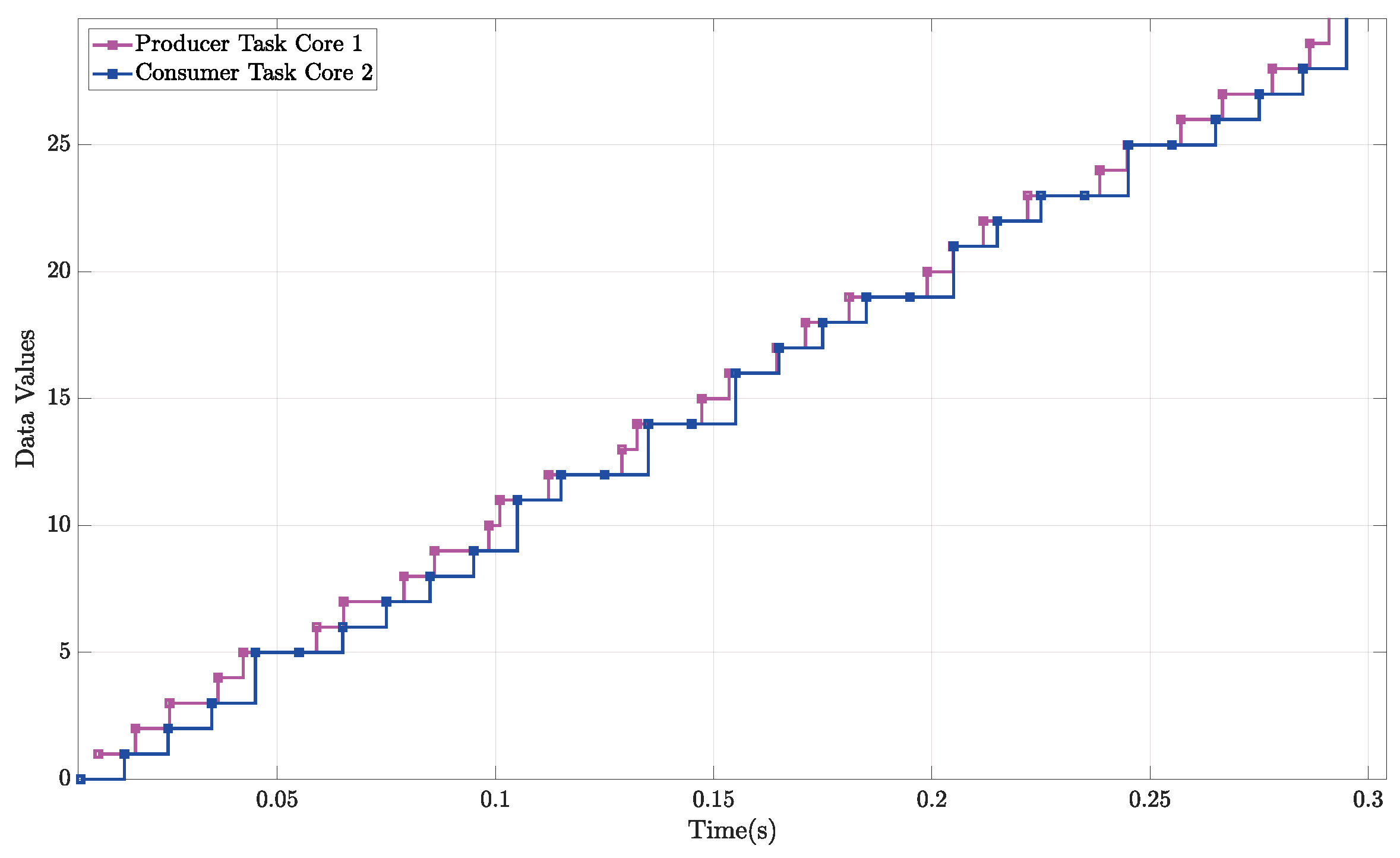
The data shown in Figure 2 demonstrate the challenges of transferring data between cores, which can lead to a loss of signal resolution and potentially affect the performance of application algorithms. For this example, the modeling was conducted using a modeling and simulation environment such as Simulink’s SoC Blockset. The timing reference for the example is managed by the simulation setup, starting at 0 at the beginning of the execution.
In this scenario, a producer task was designed to run at a fixed rate of 10 ms on the primary core, triggered by an external event representing any scheduler event or an ISR in the operating system. To simulate unpredictable delays caused by external events like task preemption, ISRs, or execution jitter, the data output was generated at random times. The output was written to a shared buffer without any synchronization mechanisms, meaning that write operations could occur at any time during execution. A similar consumer task was designed to run on a secondary core at a fixed rate of 10 ms, also triggered by an external event. The consumer task read the input data from the shared buffer at the beginning of its execution.
Both tasks were designed to run concurrently in parallel core models and exchanged data at different points in time, which affected predictability. Data flow consistency is compromised when write operations occur after read operations, leading to the loss of data samples. This degradation can significantly impact software performance, especially in critical applications where composability and predictability are essential, such as in safety-critical systems.

3.1. LET in Multicore Systems

For single-core systems, similar issues arise, as mentioned in Section 1. For example, if a provider task exhibits jittering frequency, consumer tasks may lose samples, thereby affecting the performance of the algorithms they execute. To address this issue, Logical Execution Time (LET) was developed. Predictability is crucial for time-critical applications, as it enables the modeling and optimization of event chains. Modeling event chains helps determine the order and scheduling of tasks, thus minimizing sampling jitter and improving the performance of algorithm execution. In the realm of real-time multicore systems, the Logical Execution Time (LET) model stands out as a technique for ensuring system predictability and temporal isolation. Initially introduced by Giotto as a time-triggered programming language, the LET model addresses concurrency issues with its straightforward strategies and time determinism, thereby improving system predictability and simplifying certification processes [29]. The fundamental principle of the LET model involves setting fixed times for operations on memory resources, significantly reducing contention over shared resources and thus enhancing overall system performance. This enhancement is particularly beneficial, as it streamlines both the system design and analytical processes. Moreover, the LET model plays an essential role in managing the complexities of concurrent access to shared memory, which is especially critical in multicore environments. By mitigating these complexities, the LET model greatly enhances system robustness and reliability. This is particularly vital in applications where precision and timely responses are essential, such as in safety-critical and time-sensitive operations. The impact of the LET model extends beyond just performance enhancement; it introduces a structured, efficient framework for resource utilization. This optimization is critical in multicore systems, where the coordination of multiple cores requires a balance between resource allocation and execution efficiency. Ultimately, the LET model delivers a predictable and efficient execution of tasks, making it an indispensable tool in real-time multicore system design.
In a real-time system, the tasks that must be executed are defined. Each task has a specific purpose and is designed to be executed within a set time. The LET process is as follows:
  • Assignment of a LET to a Task: A task requiring a Logical Execution Time (LET) needs data consistency and coherency during its execution. This is crucial when the task is part of an event chain where data must remain consistent and predictable throughout the chain. These tasks should have periodic executions, independent of their preemption characteristics. The LET assigned to such tasks defines the period during which they must perform their operations on shared memory. The LET is a fixed and predictable period that should match the rate of the task activation.
  • Start of the LET Period: At the beginning of the LET period, read operations to shared memory are performed before the task starts its execution. This start is typically triggered by a system clock or an external event. Data read from shared memory are stored in the local context of the task, enabling it to perform operations locally.
  • Execution of the Task’s Logic: During the LET, the task executes its logic, which may include data processing, decision-making, or interaction with other system components. During this time, output data that need to be written to shared memory are stored in local buffers to avoid contention.
  • Completion of Execution: The task must complete its execution within the assigned LET period. If the task finishes before the LET period expires, it remains suspended until its next activation period. At the end of the LET, the output data are written to shared memory, ensuring data consistency and predictability throughout the system. Once the current LET ends, the next LET period begins, either for the same task or for a group of tasks in the system.
Figure 3 shows a visual representation to understand the operational dynamics of the LET model.
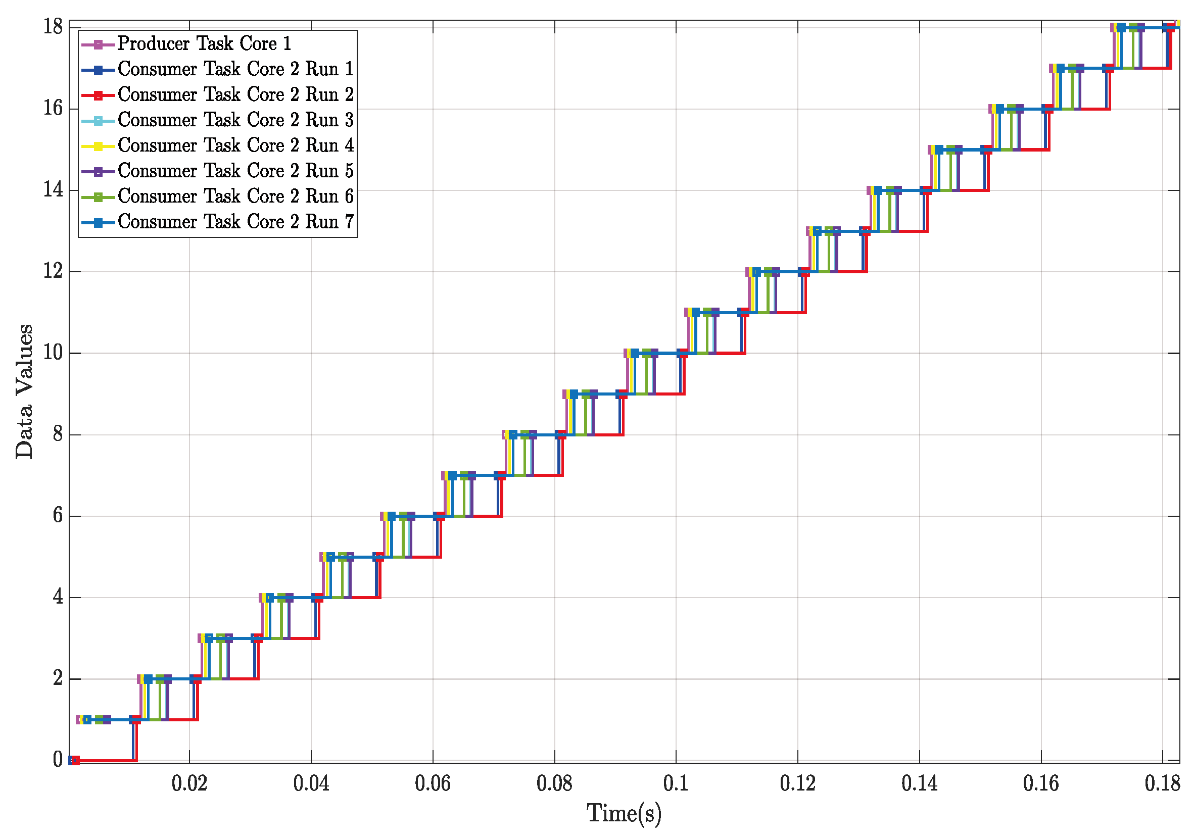
While the LET model enhances predictability and data consistency in multicore real-time systems, it has some limitations, as it was initially designed for classical single-core real-time systems. The model does not account for the parallel execution of multiple tasks across different cores. Each core operates with an independent scheduler, resulting in read/write operations with different timings across cores, even when operations are fixed at the core task level. Figure 4 illustrates an example of various executions of different tasks allocated to different cores using Simulink’s SoC Blockset. This scenario was modeled for the producer task to start periodic execution every 10 ms at t = 0. The consumer periodic task was set to have a rate of 10 ms with a variable start time to emulate variable initialization times. Although the cycle time was fixed, the offset between the tasks on each core varied on each simulation run. These tasks included producer–consumer pairs, a simulation of real-time data acquisition tasks, and synchronized transmission tasks.

TDMA in Multicore Systems

Time-Division Multiple Access (TDMA) is a time-slot method widely used in communications and embedded systems. According to [30], TDMA is a time-triggered communication technology where the time axis is statically divided into slots, with each slot statically assigned to a component. A component is permitted to send a message only during its designated slot. Figure 5 illustrates a simple example of a single channel shared among four transmitter entities and four receiver entities to exchange data within a given time period T. The channel can be any transmission medium, such as a memory cell or a carrier signal.
This concept allows data-producing entities to utilize the full channel capacity to transmit information during a defined time interval, while consumer entities can access this information within the same timeframe. In a channel, information is only available during a specific period, necessitating time synchronization to ensure the desired data are transmitted to the intended recipients. This method is also resource-efficient, as multiple producers and consumers can share a single channel. In embedded systems, resources are limited and time constraints exist; therefore, TDMA has been widely adopted to address scheduling and resource management challenges. With this setup, emitters can transmit data at a fixed rate, while receivers can read data within the same time slots, facilitating communication synchronization and optimizing channel capacity by allowing multiple transmitters to use the same channel through time-slot multiplexing. TDMA has been proposed as a solution in several studies. For instance, Ref. [31] included it as part of a memory controller that allows both critical and non-critical applications to access memory without interference. Similarly, Ref. [19] suggested TDMA for overlapping the memory and execution phases of task segments. Figure 6 illustrates how data exchange is scheduled between tasks on different cores.

4. Methodology

In time-critical systems, it is important to have predictable event chains in order to model and improve performance more effectively. However, in real-time embedded multicore systems, there are challenges due to processing cores running in parallel with different initialization times, core frequencies, and operating systems. This parallelism affects the performance of the LET model, as it does not consider the concurrent execution of tasks. The time it takes between read and write operations can vary depending on each core’s events, like initialization, interrupts, and preemption, leading to varying latency and reduced predictability of data flow. To address the issue of variable latency in inter-core communication, TDMA is proposed as a complement to the LET model. While the LET model handles read/write operations within a single processing core, TDMA can be used for inter-core data exchange, offering improved composability. TDMA is predictable and composable.
Predictability is the ability to provide an upper bound on the timing properties of a system. Composability is the ability to integrate components while preserving their temporal properties. Although composability implies predictability, the opposite is not true. A round-robin arbiter, for instance, is predictable, but not composable. A TDM (Time Division Multiplexing) arbiter, on the other hand, is predictable and composable [31].

4.1. Implementation of LET Plus TDMA in Multicore Systems

In a multicore real-time system, write/read operations can be synchronized to the channel using any notification mechanism, enabling data exchange between cores independently of the task-executing algorithms and at a fixed rate. This synchronization allows for predicting data flow behavior based on this model. In real hardware, timing depends on memory cache times and the selected synchronization mechanism (e.g., ISRs (Interrupt Service Routines), OS task, or specific hardware). Despite these dependencies, the minimal latency between operations can be calculated and further optimized.
In this work, we develop a method to address these challenges by combining the predictability and data consistency of the LET model with the composability of TDMA. This implementation is shown in Figure 7 and is described as follows:
  • Determine the TDMA time intervals for communication between tasks on different cores that require sharing information. Assign specific time windows during which a task can transmit data through the communication channel.
  • Assign an execution period to each task (LET), defining when the task should start its execution and when its results must be available. Additionally, set and fix the reading and writing times statically, allowing the system to behave predictably, as each task’s operations on shared memory have a defined execution period.
  • Coordinate and plan the TDMA intervals with the LET execution times of the tasks to ensure that communication occurs without conflicts, thereby enabling communication within the TDMA intervals without interference.
  • Implement mechanisms to synchronize the LET task groups with the same LET periods with their corresponding TDMA slots, maintaining the execution of tasks within the TDMA and LET processes.
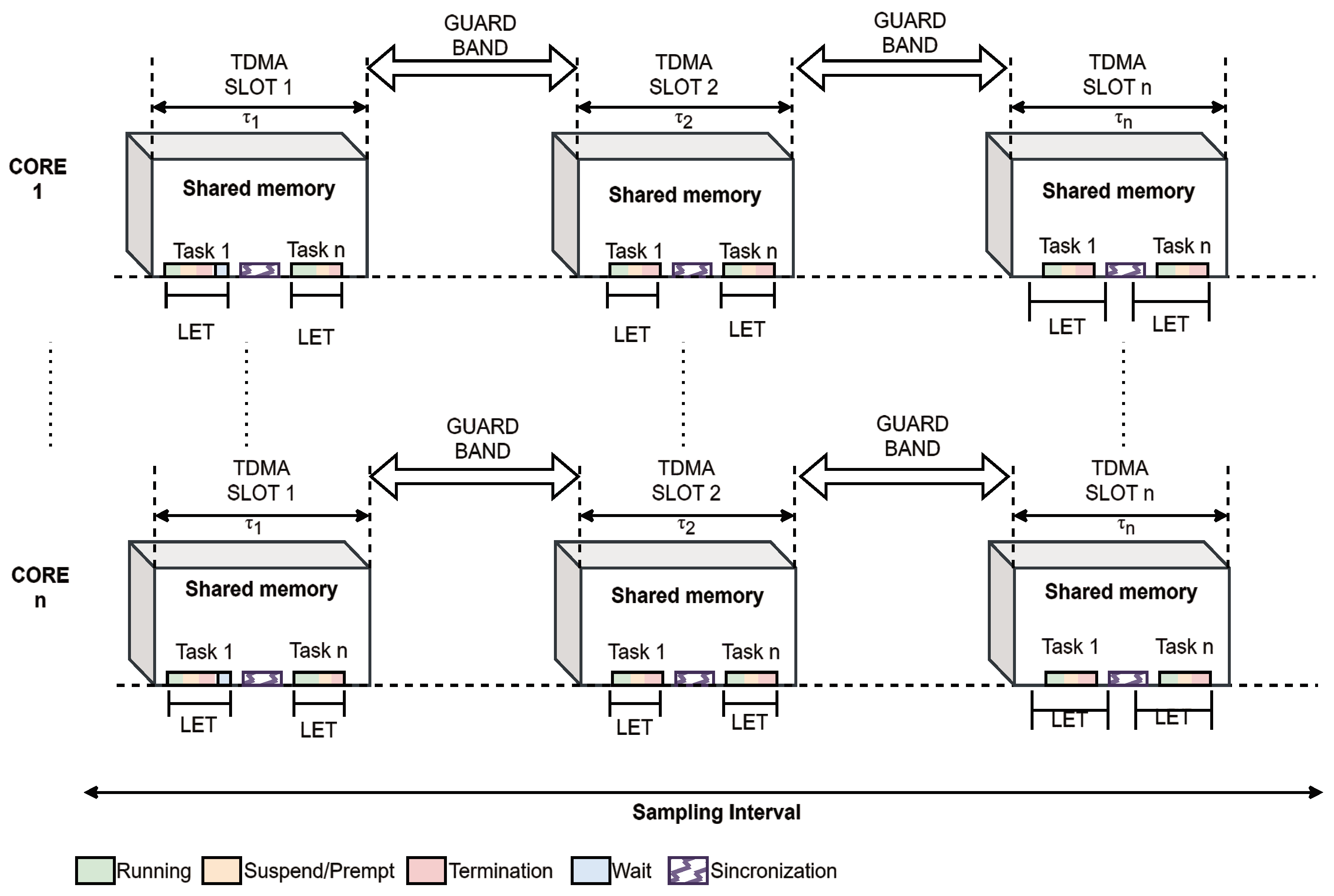
Figure 7. Implementation of LET and TDMA methods in multicore real-time systems. The figure illustrates how write and read operations are synchronized across multiple cores using TDMA slots and LET intervals. Each core has its shared memory, with tasks executing within their LET intervals. Guard bands are included between TDMA slots to prevent conflicts and ensure data consistency. This combined approach enhances the predictability and composability of inter-core data exchange.
Algorithms 17 00294 g007

4.2. Implementation Details

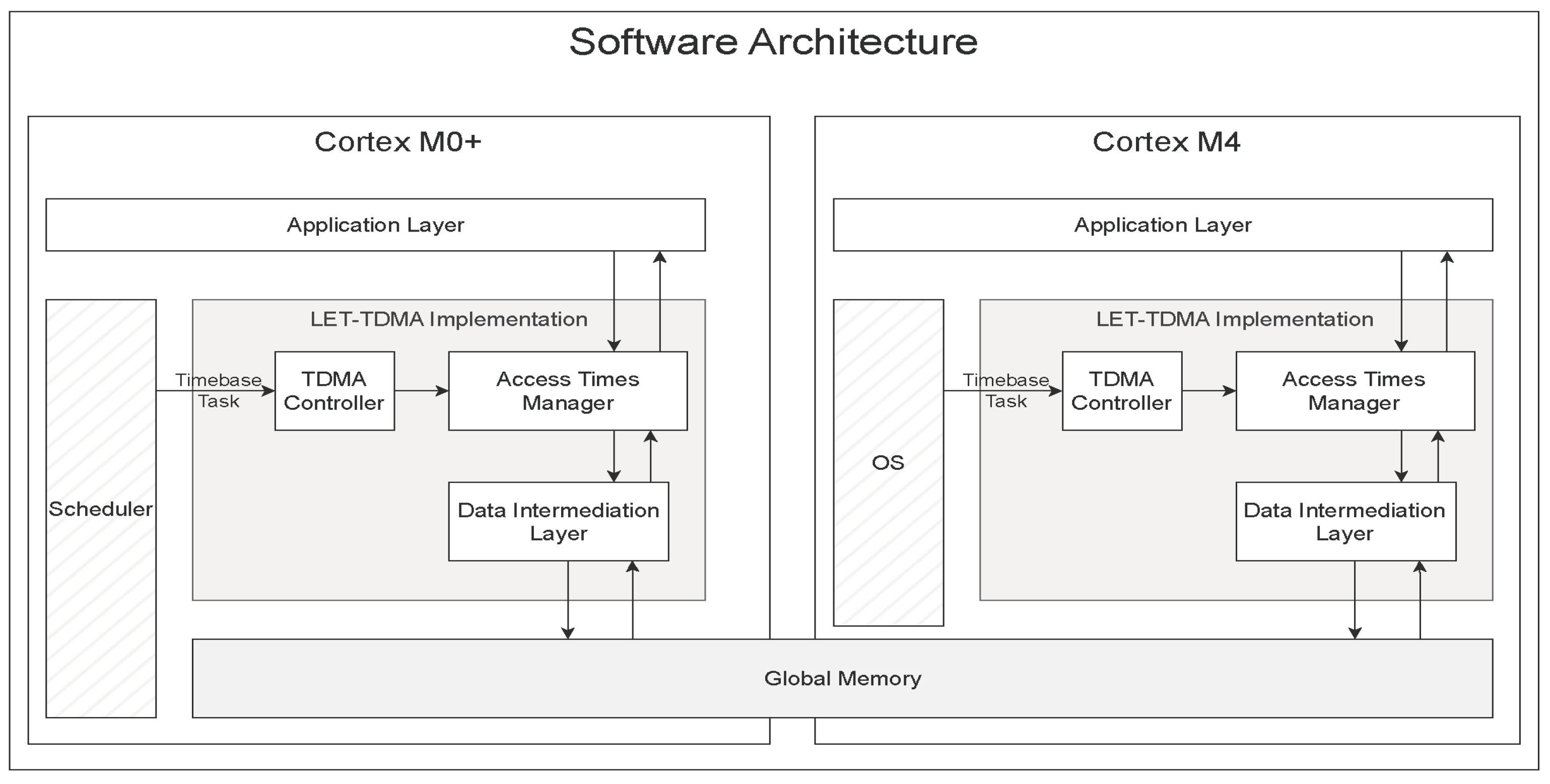
For the LET-TDMA solution implementation, we used the CYT2B75 Traveo II Entry Family Starter Kit platform, which features a 32-bit Arm Cortex-M0+ processor and an additional Arm Cortex-M4 core to handle complex tasks. The platform boasts a substantial memory architecture, including 4 MB of Flash, 128 KB of Work Flash, and 512 KB of SRAM. It supports advanced cryptographic operations with its Cortex-M0+ core and provides security features through a Memory Protection Unit (MPU) and a Shared Memory Protection Unit (SMPU). The software implementation was designed with a three-layer architecture to decouple hardware-specific software for shared memory static allocation and access from model-specific software. This architecture comprises three layers: hardware-specific software, LET operations, and TDMA management. Figure 8 illustrates the architecture developed, highlighting the interconnected layers designed to optimize both the flow and the consistency of the information.
The first of these layers is the Data Intermediation Layer, which manages the shared memory used by various software components to access common information. This layer provides APIs to manage direct access to shared buffers, which are declared through a configuration header. Platform-specific labels must be provided in the configuration files to provide the linker with the memory address range for allocating the shared buffers and controlling data in the global RAM.
The Access Times Manager Layer establishes the times for read and write operations for cross-core LET and performs the write operation between local and shared buffers. As input configuration, this layer requires the periods from tasks allocated to different cores belonging to the same event chain. It also requires the local buffer sizes to handle data copy operations at the LET periods. Its main functions include the following:
  • Enqueue: Organizes writing tasks from local memory to shared memory, acquiring local memory addresses from the local buffers for the writing process, and executes them throughout the task execution.
  • Trigger: Checks and transfers pending data to the designated areas of the shared memory, ensuring its availability for other processes.
  • Read: Facilitates access to the shared memory using specific identifiers to locate the necessary sections.
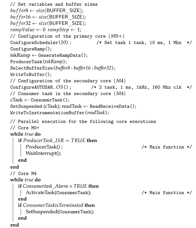
Finally, the TDMA Controller coordinates the activation and access to the assigned time slots for using shared memory among the system cores, leveraging the APIs provided by the LET layer. The TDMA Controller provides the base time for the TDMA time slots and is executed at a periodic rate driven either by an ISR or an OS scheduler-handled task with a high priority to minimize jitter or delayed access to the time slots. The timing of the base period defines the TDMA timing granularity, which for efficiency, can be calculated using the greatest common divisor of the periods of the communicating tasks. The TDMA Controller also provides the means to coordinate the activation of consumer tasks based on the availability of producer data and its configured activation period through implementation or platform-specific callbacks. The implementation of these callbacks is out of the scope of this study. Algorithm 1 illustrates the main functions of this process.
Algorithm 1: Main system operation
Algorithms 17 00294 i001

4.3. Characterization of Producer and Consumer Tasks

To validate the characterization of communication between producer and consumer tasks, the specific moments when the tasks must read and write data were calculated using Equations (1) and (2), obtained from [32].
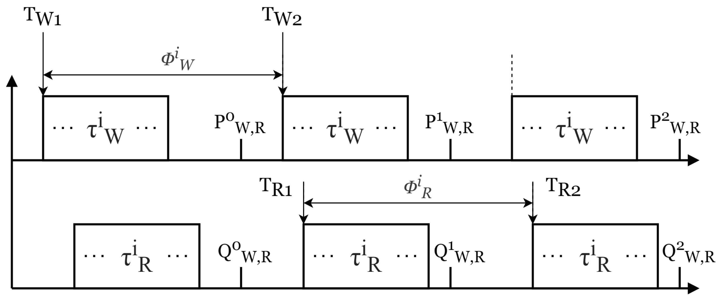
P W , R n = ϕ W + n · T max + ϕ max ϕ W T W · T W
Q W , R n = ϕ R + n · T max + ϕ max ϕ R T R · T R
where P corresponds to the execution times of the producer and Q to those of the consumer. ϕ W and ϕ R are the offsets for the writing and reading tasks, respectively. T max represents the maximum values of T W and T R , and ϕ max is the offset of the task with the largest period of the pair. Finally, T W and T R are the communication tasks for writing and reading, respectively.
According to Equations (1) and (2), predictability in publication and reading times reduces variability in task response times. The calculation of specific offsets allows for improved system determinism, as knowing the exact times of reading and writing enables precise forecasting of system behavior under various load and execution conditions. This not only enhances predictability but also provides flexibility in system design, allowing adaptation to different temporal and synchronization requirements without the need to change task periods. The diagram of this characterization is shown in Figure 9.

4.4. Characterization of End-to-End Latencies

To characterize the age, maximum age, and reaction latencies, the semantics in [7] were considered and are defined below.
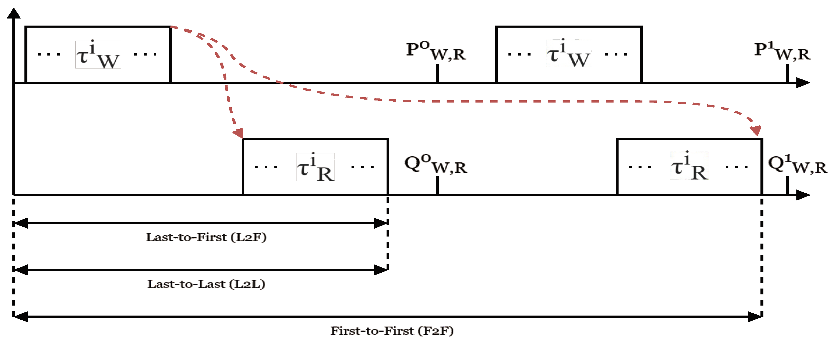
The age latency (Last-to-First, L2F) measures the delay from the last input that is not overwritten to the first output generated with the same input.
α ( E C ) = Σ i = 1 n 1 ( ϕ i l a s t + Δ i + 1 )
The reactive latency (First-to-First, F2F) measures the delay from the first input that can be overwritten to the first output generated with the next different input.
δ ( E C ) = Σ i = 1 n 1 ( ϕ i 0 + Δ i )
The maximum age latency (Last-to-Last, L2L) or maximum age measures the delay from the last input that is not overwritten to the last output, including duplicates.
α max = Σ i = 1 n 1 α i , i + 1 ( E C )
Figure 10 shows how the L 2 F latency is measured from the first input that can be overwritten to the first output generated with the next different input. The F 2 F latency is measured from the first input that can be overwritten to the first output generated with the next different input. The L 2 L latency is measured similarly to the L 2 F latency, from the last input that is not overwritten to the last output, including multiple executable instances.

4.5. Validation Methods

The Root Mean Square Error (RMSE) is a widely used accuracy metric in regression tasks to evaluate the difference between the values predicted by a model and the actual values. To calculate the RMSE, first, the difference between the predicted and actual value for each data point is calculated, and then each difference is squared to prevent the cancellation of negative and positive errors. Subsequently, these squared values are averaged, and finally, the square root of the average is taken to adjust the errors to the original scale of the data. This metric is especially useful because it gives greater weight to larger errors, which is crucial in many practical contexts where large errors are particularly undesirable. The RMSE was calculated as shown in Equation (6).
R M S E = 1 T t = 1 n ( x t x t ^ ) 2
where n is the total number of observations, x t represents the actual values, and x ^ t represents the predicted values.

5. Results

This section presents the results obtained from applying our LET-TDMA method in the dual-core Arm Cortex processor with 4 MB of Flash, 128 KB of Work Flash, and 512 KB of SRAM. An external 16 MHz crystal oscillator drove the internal clocks from both cores. The application core hosts an AUTOSAR 4.0.3-compliant OS, with Scalability Class 1. This OS features fixed priority-based scheduling, handling of interrupts, and start-up and shutdown interfaces. Table 1 shows the configuration parameters for the clocks, the memory type used for the buffers, and the number of configured tasks.
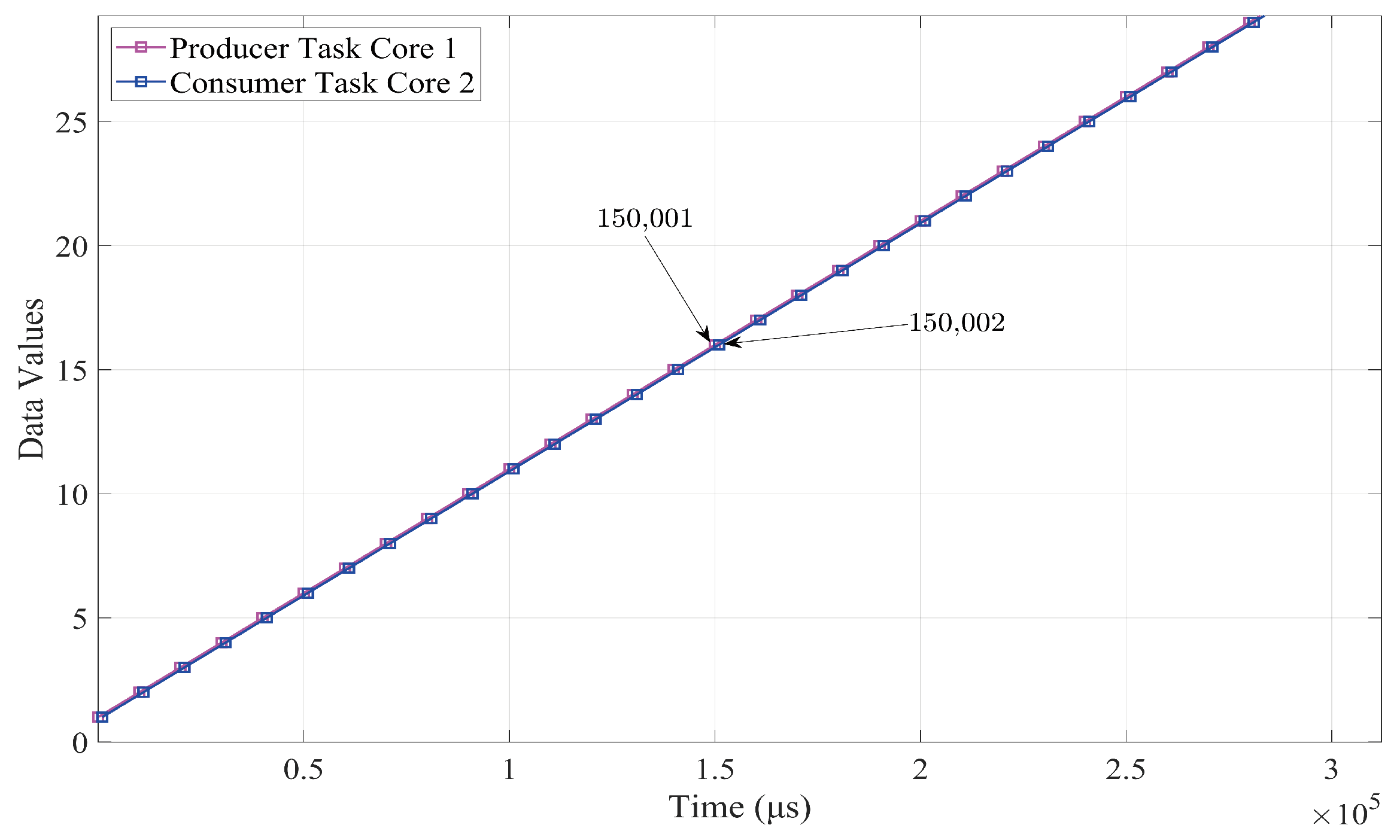
To output the measurement times of the read ( T R ) and write ( T W ) operations, the Instrumentation Trace Macrocell (ITM) hardware available in the Cortex M4 core was used, together with I-jet debugger hardware from IAR Systems and the IAR Embedded Workbench Integrated Development Environment. The two processing cores implemented an event chain with a producer task on the main core and a consumer task on the application core. The consumer task was set as a non-preemptive AUTOSAR basic task with the highest priority, while the producer task was set as a simple function called by an ISR-driven basic scheduler. The dataset to be transferred was designed to represent a simple ramp with a slope of 1, with a task cycle time set to 10 ms. Figure 11 shows the timing of write and read operations for the data values of the slope with a buffer size of 16 bits. Compared to the simulated scenario depicted in Figure 1, it is possible to see that latency in the data transfer has very low variability. Measurements for both 8-bit and 32-bit buffers yielded similar results.
The datasets generated for buffer sizes of 8, 16, and 32 bits during the experimentation are accessible in the public repository at https://github.com/acmos25/LET-TDMA, accessed on 8 June 2024.
Specifically for the configurations of the LET (ISR Core 0 with AUTOSAR Core 1, and ISR Core 0 with ISR Core 1) and LET-TDMA (ISR Core 0 with AUTOSAR Core 1) implementations. Through the experiments, the execution time, accuracy, and latency were evaluated. Comparative analyses were conducted between different system configurations to assess the impact of buffer sizes on system performance. Table 2 shows the behavior of this scenario, including data samples from the write operations on the main core and the read operations on the application core.
Table 3, Table 4 and Table 5 provide samples of the times for data written ( T W ) and the times for data read ( T R ). These times are crucial for maintaining an operational sequence and ensuring effective coordination between concurrently operating components. Offsets ϕ W and ϕ R were applied to these temporal records to synchronize operations between tasks that require coordinated interaction despite being independent. These values were calculated by obtaining the difference in execution times between the write and read tasks ( T W , R i T W , R i 1 ), as illustrated in Figure 9. Furthermore, the parameter T max establishes the maximum interval within which tasks must be coordinated, acting as a reference period for the task execution cycle. The values of ϕ max indicate the additional adjustment needed to synchronize producer and consumer operations.
Figure 12 shows the results of calculating the values of P W , R and Q W , R , which are identical at all calculated data points. These ensure that both read and write execution tasks operate at synchronized moments, thus avoiding desynchronization between operations. Figure 12a–c represent the values of P W , R and Q W , R for buffer sizes of 8, 16, and 32 bits, respectively.
Table 6 presents the analysis of communication methods in multicore systems, where the LET model stands out for its high predictability and consistency in response times, crucial attributes for applications that require temporal synchronization. LET’s ability to provide consistent and predictable response times makes it ideal for real-time control environments and critical safety applications. However, its implementation is more complex and requires detailed planning of Logical Execution Times. On the other hand, the combination of TDMA-DMA and SPM demonstrates advantages for applications that can benefit from optimized memory management, thus improving overall system performance and reducing wait and processing times.
Additionally, explicit communication tends to show less variability in reactive latency times compared to implicit communication. This lower variability is required for applications that need consistent and reliable response times, as it reduces uncertainty and improves the predictability of system behavior. However, it can increase programming complexity and the overhead of synchronization management. Meanwhile, implicit communication simplifies implementation by automatically managing synchronization, but it presents greater variability in latency times and less predictability, which can lead to synchronization problems. Nevertheless, the combination of LET and TDMA has shown that the predictability and consistency of Logical Execution Time applied to task communication, along with the composability of time-controlled buffers, ensures consistent latency and temporal determinism for communication between cores in 8-bit, 16-bit, and 32-bit architectures. This reduces the need to link applications to specific cores, facilitating the creation of less dependent event chains.
In this work, the LET implementation in a dual-core processor was first reproduced to measure its variability against our LET-TDMA method. The setup used the same conditions as those in the LET-TDMA experimentation: two processing cores implementing an event chain of producer and consumer tasks. The dataset to be transferred was defined to represent a simple ramp with a slope of 1. The task cycle times were set to 10 ms. Table 7 shows the RMSE values calculated using Equation (6). This case depicts how variable the LET case behaves due to the task activation latency introduced by the AUTOSAR OS on the M4 core compared to the execution of the ISR-based task on the M0+ core, which was measured to increase by 62.5 ns on each task activation. In contrast, the LET-TDMA solution maintains the time between read and write operations at an average of 1.00143 ms, exhibiting very low variability with a maximum time of 1.002 ms and a minimum delay of 1.001 ms.
Figure 13 shows the plotted time differences between the producer write operations and the consumer read operations using the proposed LET-TDMA solution. From this information, it can be deduced that the RMSE calculation is consistent with the actual measured time differences between the write and read operations.

6. Discussion

Integrating LET and TDMA models in multicore systems represents a significant advancement in managing inter-core communication. This study demonstrates that combining these methodologies can effectively address the inherent challenges of synchronization and data consistency in real-time critical systems. At first glance, it is evident that tasks on different cores significantly benefit from the implementation of the LET model, ensuring temporal predictability with fixed operation times for read and write operations. According to the results obtained, there is no data loss when maintaining constant read/write operation rates. However, a variable that still requires improvement is data transfer latency when implemented in multicore systems. The LET model faces challenges due to variability in initialization and execution times on each core, as well as in dispatcher times, which can introduce variable latencies in data communication between cores. These challenges depend on the application and the operating system, especially in heterogeneous core configurations.
The proposed method combines LET with TDMA-managed buffers to mitigate variable latency issues in inter-core communication. This is achieved by synchronizing the read operation of the consumer task on one core with the write operation of the producer task on another core, ensuring each task has defined access times to the communication channels. According to the results obtained, it is evident that the LET model greatly benefits from integration with TDMA when applied in multicore systems. This integration not only reduces variability in response times but also improves the system’s consistency and predictability. Fixing the latency also makes the system more deterministic, as variability in read and write operations can affect the performance of time-critical algorithms.
TDMA also provides efficient resource usage since global buffers can be shared across several tasks from different cores due to the temporal isolation provided by this scheme, which allows for the reuse of buffers across time slots while eliminating waiting times introduced by synchronization mechanisms, such as semaphores or spinlocks. Considering various example scenarios such as producer–consumer tasks, real-time data acquisition in industrial control systems, and synchronized data transmission in telecommunications, buffer usage can be optimized. For instance, in a scenario with four pairs of tasks with execution periods that are the same or multiples, buffer usage can be reduced by up to 75% if all pairs can use the same buffer if the required buffer sizes are the same or lower than the maximum buffer size. Similarly, in industrial control systems, synchronization of sensor data acquisition and actuator control can be enhanced using these principles.
In microcontrollers, defined operation times and the absence of resource locks may lead to lower energy consumption, but that is not the focus of this work. As mentioned at the beginning of this document, low latency and determinism are crucial to ensuring the safety of critical embedded systems. These systems, found in the automotive and aviation industries, require high predictability and consistency in data transfer to guarantee system performance and safety. Integrating LET with TDMA provides a strong and efficient solution, ensuring that tasks distributed across different cores can communicate predictably and without data loss, thus optimizing overall system performance.

7. Conclusions and Future Directions

In this study, we have introduced a communication model between cores that combines the predictability of Logical Execution Time with a synchronization mechanism in heterogeneous systems and the composability of time-controlled buffers. This is achieved using a Time-Division Multiple Access scheme for inter-core communication. Given the critical nature of deadlines in real-time tasks, this approach ensures constant latency between tasks on different cores using a shared memory channel, addressing hardware limitations and timing dependencies. This reduces the need to bind applications to specific cores and facilitates the creation of less dependent event chains.
Furthermore, by establishing time intervals for data transfer between cores, deterministic data flows can be modeled. The portability of this approach allows it to be used across various platforms, as it is not tied to specific hardware implementations. Our analysis and results demonstrate the following: (a) Improved temporal predictability: The integration of LET with TDMA improves the temporal predictability of read and write operations in multicore systems, achieving a constant latency of 11 ms. (b) Reduced variable latency: Measurements of data transfer between cores using shared buffers of 8, 16, and 32 bits showed a latency of approximately 1 ms, enhancing system consistency, compared to the LET model, which showed variable latencies of 3.2846 ms, 8.9257 ms, 0.2338 ms for 8, 16 and 32 bits. (c) Enhanced system consistency: Implementing this method enabled predictable and synchronized access times to shared resources, with access times improving to 10 ms, thereby enhancing system consistency. Moreover, the TDMA implementation allows global buffers to be shared among multiple tasks across different cores due to the temporal isolation of this scheme, making them reusable within defined time intervals.
Despite its performance benefits, this method faces certain limitations. The event chains were limited to two tasks and one label each, focusing on latency improvement on a dual-core embedded microcontroller. RAM was used for shared buffers, and LET management was independent of the Runtime Environment (RTE) and operating system software. The reference conditions in this study focused on evaluating the real impact of the cross-core LET-TDMA implementation and its improvements. However, in more complex configurations with event chains distributed across more than two cores, data loss could still occur, especially in systems handling multiple external events. Balancing external event handling is crucial to avoid TDMA scheduling disruptions.
Future work could explore expanding this technique to support more cores by distributing event chains across multiple cores. Integrating LET-TDMA management as an RTE implementation addon could simplify inter-core event chaining through configuration and code generation. Additionally, optimizing shared buffer strategies using technologies like DMA or platform-specific inter-process communication implementations, abstracted through standardized interfaces, remains a relevant topic for future research.

Author Contributions

Conceptualization, C.-A.M.-A. and J.-A.R.-G.; methodology, C.-A.M.-A. and J.-A.R.-G.; software, C.-A.M.-A.; validation, C.-A.M.-A., J.-A.R.-G., D.-M.C.-E., J.R.-R. and J.T.; formal analysis, C.-A.M.-A., J.-A.R.-G., D.-M.C.-E., R.C.-S. and J.T.; investigation, C.-A.M.-A., J.-A.R.-G., D.-M.C.-E., R.C.-S., J.T. and J.R.-R.; resources, J.R.-R.; data curation, C.-A.M.-A., J.-A.R.-G., D.-M.C.-E., R.C.-S., J.R.-R. and J.T.; writing—original draft preparation, C.-A.M.-A. and J.-A.R.-G.; writing—review and editing, C.-A.M.-A., J.-A.R.-G., D.-M.C.-E., R.C.-S., J.T. and J.R.-R.; visualization, C.-A.M.-A., J.-A.R.-G., D.-M.C.-E., R.C.-S., J.T. and J.R.-R.; supervision, C.-A.M.-A., J.-A.R.-G., D.-M.C.-E., R.C.-S., J.T. and J.R.-R.; project administration, C.-A.M.-A., J.-A.R.-G., D.-M.C.-E., R.C.-S., J.T. and J.R.-R.; funding acquisition, C.-A.M.-A., J.-A.R.-G., D.-M.C.-E., R.C.-S., J.T. and J.R.-R. All authors have read and agreed to the published version of the manuscript.

Funding

This research received no external funding.

Data Availability Statement

Raw data for 8-, 16-, and 32-bit buffer sizes are available at https://github.com/acmos25/LET-TDMA (accessed on 3 July 2024) for the LET (ISR Core 0 with AUTOSAR Core 1, and ISR Core 0 with ISR Core 1) and LET-TDMA (ISR Core 0 with AUTOSAR Core 1) implementations.

Acknowledgments

We thank the Autonomous University of Queretaro and the National Council of Humanities, Sciences, and Technologies (CONAHCYT) for the Master’s scholarship.

Conflicts of Interest

The authors declare no conflicts of interest.

Abbreviations

The following abbreviations are used in this manuscript:
AUTOSARAUTOmotive Open System ARchitecture
CABCyclic Asynchronous Buffer
DMADirect Memory Access
F2FFirst-to-First
GASAGenetic Simulated Annealing Optimization
ISRInterrupt Service Routines
L2FLast-to-First
L2LLast-to-Last
LETLogical Execution Time
MoDGWAMulti-objective cost-aware Discrete Gray-Wolf optimization-based Algorithm
MPUMemory Protection Unit
NoCNetwork-on-a-Chip
NVMNon-Volatile Memory
OSOperative System
POSIXPortable Operating System Interface
RAMRandom Access Memory
RMSERoot Mean Squared Error
RTERuntime Environment
SFFScheduling Failure Factor
SLSystem level
SMPUShared Memory Protection Unit
SPMScratchPad Memories
SRAMStatic Random Access Memory
TDMTime-Division Multiplexing
TDMATime-Division Multiple Access
TIMEATime-Triggered Message-Based Architecture

References

  1. Nidamanuri, J.; Nibhanupudi, C.; Assfalg, R.; Venkataraman, H. A progressive review: Emerging technologies for ADAS driven solutions. IEEE Trans. Intell. Veh. 2021, 7, 326–341. [Google Scholar] [CrossRef]
  2. Antinyan, V. Revealing the Complexity of Automotive Software. In Proceedings of the 28th ACM Joint Meeting on European Software Engineering Conference and Symposium on the Foundations of Software Engineering (ESEC/FSE 2020), Sacramento, CA, USA, 6–16 November 2020; pp. 1525–1528. [Google Scholar] [CrossRef]
  3. Monot, A.; Navet, N.; Bavoux, B.; Simonot-Lion, F. Multicore scheduling in automotive ECUs. Embedded Real Time Software and Systems; ERTSS: Toulouse, France, 2010. [Google Scholar]
  4. Bucaioni, A.; Mubeen, S.; Ciccozzi, F.; Cicchetti, A.; Sjödin, M. Modelling multi-criticality vehicular software systems: Evolution of an industrial component model. Softw. Syst. Model. 2020, 19, 1283–1302. [Google Scholar] [CrossRef]
  5. Schoeberl, M.; Sørensen, R.B.; Sparsø, J. Models of communication for multicore processors. In Proceedings of the 2015 IEEE International Symposium on Object/Component/Service-Oriented Real-Time Distributed Computing Workshops, Auckland, New Zealand, 13–17 April 2015; IEEE: Piscataway, NJ, USA, 2015. [Google Scholar]
  6. Hamann, A.; Dasari, D.; Kramer, S.; Pressler, M.; Wurst, F. Communication centric design in complex automotive embedded systems. Leibniz Int. Proc. Inform. LIPIcs 2017, 76, 101–1020. [Google Scholar] [CrossRef]
  7. Martinez, J.; Sañudo, I.; Bertogna, M. End-to-End Latency Characterization of Task Communication Models for Automotive Systems; Springer Nature: Heidelberg, Germany, 2020; Volume 56, pp. 315–347. [Google Scholar] [CrossRef]
  8. Pazzaglia, P.; Biondi, A.; Di Natale, M. Optimizing the functional deployment on multicore platforms with logical execution time. Proc. Real-Time Syst. Symp. 2019, 2019, 207–219. [Google Scholar] [CrossRef]
  9. Toscanelli, M. Multicore Software Development for Engine Control Units. Master’s Thesis, Università di Bologna, Bolonia, Italia, 2019. [Google Scholar]
  10. Cerrolaza, J.P.; Obermaisser, R.; Abella, J.; Cazorla, F.J.; Grüttner, K.; Agirre, I.; Ahmadian, H.; Allende, I. Multi-core devices for safety-critical systems: A survey. ACM Comput. Surv. (CSUR) 2020, 53, 1–38. [Google Scholar] [CrossRef]
  11. Igarashi, S.; Azumi, T. Work in progress: Considering heuristic scheduling for NoC-Based clustered many-core processor using LET model. In Proceedings of the Real-Time Systems Symposium, Hong Kong, China, 3–6 December 2019; Institute of Electrical and Electronics Engineers Inc.: Piscataway, NJ, USA, 2019; pp. 516–519. [Google Scholar] [CrossRef]
  12. Hung, S.H.; Chiu, P.H.; Shih, C.S. Building and optimizing a scalable and portable message-passing library for embedded multicore systems. Information 2012, 15, 3039–3057. [Google Scholar]
  13. Hung, S.H.; Tu, C.H.; Yang, W.L. A portable, efficient inter-core communication scheme for embedded multicore platforms. J. Syst. Archit. 2011, 57, 193–205. [Google Scholar] [CrossRef]
  14. Sørensen, R.B.; Puffitsch, W.; Schoeberl, M.; Sparsø, J. Message passing on a time-predictable multicore processor. In Proceedings of the 2015 IEEE 18th International Symposium on Real-Time Distributed Computing, ISORC 2015, Auckland, New Zealand, 13–17 April 2015; pp. 51–59. [Google Scholar] [CrossRef]
  15. Urbina, M. TIMEA: Time-Triggered Message-Based Multicore Architecture for AUTOSAR. Ph.D. Thesis, University of Siegen, Siegen, Germany, 2020. [Google Scholar]
  16. Beckert, M. Scheduling Mechanisms for Efficient and Safe Automotive Systems Integration. Ph.D. Thesis, Technischen Universität Braunschweig, Braunschweig, Germany, 2019. [Google Scholar] [CrossRef]
  17. Shirvani, M.H.; Talouki, R.N. A novel hybrid heuristic-based list scheduling algorithm in heterogeneous cloud computing environment for makespan optimization. Parallel Comput. 2021, 108, 102828. [Google Scholar] [CrossRef]
  18. Seifhosseini, S.; Shirvani, M.H.; Ramzanpoor, Y. Multi-objective cost-aware bag-of-tasks scheduling optimization model for IoT applications running on heterogeneous fog environment. Comput. Netw. 2024, 240, 110161. [Google Scholar] [CrossRef]
  19. Soliman, M.R.; Gracioli, G.; Tabish, R.; Pellizzoni, R.; Caccamo, M. Segment streaming for the three-phase execution model: Design and implementation. In Proceedings of the 2019 IEEE Real-Time Systems Symposium (RTSS), Hong Kong, China, 3–6 December 2019; pp. 260–273. [Google Scholar] [CrossRef]
  20. Tabish, R.; Mancuso, R.; Wasly, S.; Pellizzoni, R.; Caccamo, M. A real-time scratchpad-centric OS with predictable inter/intra-core communication for multi-core embedded systems. Real-Time Syst. 2019, 55, 850–888. [Google Scholar] [CrossRef]
  21. Bellassai, D.; Biondi, A.; Biasci, A.; Morelli, B. Supporting logical execution time in multi-core POSIX systems. J. Syst. Archit. 2023, 144, 102987. [Google Scholar] [CrossRef]
  22. Gemlau, K.B.; KÖHLER, L.; Ernst, R.; Quinton, S. System-Level Logical Execution Time: Augmenting the Logical Execution Time Paradigm for Distributed Real-Time Automotive Software. ACM Trans. Cyber-Phys. Syst. 2021, 5, 1–27. [Google Scholar] [CrossRef]
  23. Gemlau, K.B.; Kohler, L.; Ernst, R. A Platform Programming Paradigm for Heterogeneous Systems Integration. Proc. IEEE 2021, 109, 582–603. [Google Scholar] [CrossRef]
  24. Kang, D.; Oh, J.; Choi, J.; Yi, Y.; Ha, S. Scheduling of Deep Learning Applications Onto Heterogeneous Processors in an Embedded Device. IEEE Access 2020, 8, 43980–43991. [Google Scholar] [CrossRef]
  25. Hosseini Shirvani, M. A hybrid meta-heuristic algorithm for scientific workflow scheduling in heterogeneous distributed computing systems. Eng. Appl. Artif. Intell. 2020, 90, 103501. [Google Scholar] [CrossRef]
  26. Verucchi, M.; Theile, M.; Caccamo, M.; Bertogna, M. Latency-Aware Generation of Single-Rate DAGs from Multi-Rate Task Sets. In Proceedings of the 2020 IEEE Real-Time and Embedded Technology and Applications Symposium (RTAS), Sydney, Australia, 21–24 April 2020; pp. 226–238. [Google Scholar] [CrossRef]
  27. Noorian Talouki, R.; Hosseini Shirvani, M.; Motameni, H. A hybrid meta-heuristic scheduler algorithm for optimization of workflow scheduling in cloud heterogeneous computing environment. J. Eng. Des. Technol. 2022, 20, 1581–1605. [Google Scholar] [CrossRef]
  28. Becker, M.; Dasari, D.; Mubeen, S.; Behnam, M.; Nolte, T. End-to-end timing analysis of cause-effect chains in automotive embedded systems. J. Syst. Archit. 2017, 80, 104–113. [Google Scholar] [CrossRef]
  29. Igarashi, S.; Ishigooka, T.; Horiguchi, T.; Koike, R.; Azumi, T. Heuristic Contention-Free Scheduling Algorithm for Multi-core Processor using LET Model. In Proceedings of the 2020 IEEE/ACM 24th International Symposium on Distributed Simulation and Real Time Applications, DS-RT 2020, Prague, Czech Republic, 14–16 September 2020. [Google Scholar] [CrossRef]
  30. Kopetz, H. Real-Time Systems: Design Principles for Distributed Embedded Applications, 2nd ed.; Springer: New York, NY, USA, 2011. [Google Scholar] [CrossRef]
  31. Ecco, L.; Tobuschat, S.; Saidi, S.; Ernst, R. A mixed critical memory controller using bank privatization and fixed priority scheduling. In Proceedings of the RTCSA 2014—20th IEEE International Conference on Embedded and Real-Time Computing Systems and Applications, Chongqing, China, 20–22 August 2014. [Google Scholar] [CrossRef]
  32. Martinez, J.; Sañudo, I.; Bertogna, M. Analytical Characterization of End-to-End Communication Delays With Logical Execution Time. IEEE Trans. Comput.-Aided Des. Integr. Circuits Syst. 2018, 37, 2244–2254. [Google Scholar] [CrossRef]
  33. Biondi, A.; Pazzaglia, P.; Balsini, A.; Natale, M.D. Logical Execution Time Implementation and Memory Optimization Issues in AUTOSAR Applications for Multicores. In Proceedings of the 8th International Workshop on Analysis Tools and Methodologies for Embedded and Real-Time Systems (WATERS), Dubrovnik, Croatia, 27 June 2017. [Google Scholar]
  34. Maia, L.; Fohler, G. Reducing End-to-End Latencies of Multi-Rate Cause-Effect Chains for the LET Model. arXiv 2023, arXiv:2305.02121. [Google Scholar]
  35. Wang, S.; Li, D.; Sifat, A.H.; Huang, S.Y.; Deng, X.; Jung, C.; Williams, R.; Zeng, H. Optimizing Logical Execution Time Model for Both Determinism and Low Latency. arXiv 2024, arXiv:2310.19699. [Google Scholar]
  36. Günzel, M.; Chen, K.H.; Ueter, N.; von der Brüggen, G.; Dürr, M.; Chen, J.J. Compositional Timing Analysis of Asynchronized Distributed Cause-effect Chains. ACM Trans. Embed. Comput. Syst. 2023, 22, 1–34. [Google Scholar] [CrossRef]
Figure 1. Explicit communication: Illustration of data read and write operations to a shared global memory (GLOBAL X) section during task execution on multicore systems, demonstrating inter-task communication handling when tasks are allocated to different cores.
Algorithms 17 00294 g001
Figure 2. Simulation of data transfer between cores using a shared buffer with explicit communication. The figure shows the data values written by the producer task on Core 1 and read by the consumer task on Core 2 over time. This simulation highlights the potential issues with data flow consistency and signal resolution due to asynchronous execution and external delays.
Algorithms 17 00294 g002
Figure 3. Visual representation of the operational dynamics of each task under the LET framework. The figure illustrates the predefined time frames within which tasks are executed. Each task follows a cycle of running, suspension/preemption, and termination, with specific periods for waiting. This structure ensures consistent and predictable execution, enhancing system predictability and reliability.
Algorithms 17 00294 g003
Figure 4. Simulation of eight executions with varying latencies between read and write operations. This figure demonstrates the impact of different execution cycle starts for the receiver task on the second core. Despite having a fixed cycle time, the offset between tasks on each core varies, highlighting the challenges in achieving consistent timing across multiple cores.
Algorithms 17 00294 g004
Figure 5. Illustration of a TDMA channel with four time slots. The figure shows a single channel shared among four transmitter entities (emitters) and four receiver entities (receivers), each assigned to a specific time slot (T1 to T4). This arrangement ensures that each emitter can only send data during its designated time slot, thereby avoiding conflicts and ensuring orderly data transmission.
Algorithms 17 00294 g005
Figure 6. TDMA-based memory schedule for a system with two cores. The figure depicts how data exchange is managed between tasks on different cores using TDMA. Each core has designated time slots for loading and unloading data partitions, ensuring efficient and synchronized access to shared memory. The schedule shows the allocation of segments to partitions and the usage of TDMA slots, highlighting the coordination required to prevent interference and optimize memory access.
Algorithms 17 00294 g006
Figure 8. Implementation of LET and TDMA architecture. This figure illustrates the three-layer architecture developed for real-time implementation, highlighting the Data Intermediation Layer, Latency Exchange Time Manager, and TDMA Controller. The interconnected layers are designed to optimize the flow and consistency of information, ensuring efficient and predictable data exchange in multicore systems.
Algorithms 17 00294 g008
Figure 9. Characterization of producer and consumer tasks. This figure illustrates the runnable of the writer ( τ W ) and reader ( τ R ), allowing management of the synchronization of communication between tasks with different periods and offsets in real-time systems.
Algorithms 17 00294 g009
Figure 10. This figure illustrates the measurement of the age latency (L2F), reactive latency (F2F), and maximum age latency (L2L). Additionally, the tasks ( τ i ) performed by the reader ( T R ) and writer ( T W ) are represented in relation to the synchronization times P W , R n and Q W , R n .
Algorithms 17 00294 g010
Figure 11. Measurements of data transfer between cores using a 16-bit shared buffer with the LET-TDMA method implementation. The figure shows the data values written by the producer task on Core 1 and read by the consumer task on Core 2 over time. The execution log performed on real hardware highlights the determinism and low latency variability achieved by using the proposed solution.
Algorithms 17 00294 g011
Figure 12. Variable data read/write operation times for different buffer sizes. The plots illustrate the offset times calculated for tasks at buffer sizes of 8 bits (a), 16 bits (b), and 32 bits (c). Each plot shows the read and write times for the tasks, highlighting the differences in data transfer times across varying buffer sizes.
Algorithms 17 00294 g012
Figure 13. Calculation of time differences between write and read operations between cores using a 16-bit shared buffer with the LET-TDMA method implementation. This plot highlights the low variability between data transfer operations, which directly impacts the latency calculations.
Algorithms 17 00294 g013
Table 1. Configuration parameters for the Traveo II CYT2B75 Dual-Core Microcontroller.
CoreClock
Frequency
Prescaled
Frequency
Scheduler
Handler
Base
Tick
TasksBuffer
Memory
Shared
Buffers
Buffer
Sizes (Bits)
Cortex M0+80 MHz1 MHzISR10 ms1SRAM38, 16, 32
Cortex M4160 MHz1 KHzAUTOSAR OS1 ms2SRAM38, 16, 32
Table 2. Runtime measurements for producer and consumer tasks at buffer sizes of 8, 16, and 32 bits. The table displays the write times ( T W ) for the producer task on core M0+ and the read times ( T R ) for the consumer task on core M4. The data showcase the performance and timing consistency of the LET-TDMA method across different buffer sizes.
T W 8 Bits T R 8 Bits T W 16 Bits T R 16 Bits T W 32 Bits T R 32 Bits
18,385,73718,386,73827,223,03727,224,03821,877,90221,878,904
18,395,73718,396,73827,233,03727,234,03821,887,90321,888,904
18,405,73718,406,73827,243,03727,244,03821,897,90321,898,904
18,415,73718,416,73827,253,03727,254,03821,907,90321,908,904
18,425,73718,426,73827,263,03727,264,03821,917,90321,918,904
18,435,73718,436,73827,273,03727,274,03821,927,90321,928,904
18,445,73718,446,73827,283,03727,284,03821,937,90321,938,904
18,455,73718,456,73927,293,03727,294,03921,947,90321,948,904
18,465,73718,466,73927,303,03727,304,03921,957,90321,958,904
18,475,73718,476,73927,313,03727,314,03921,967,90321,968,905
18,485,73718,486,73927,323,03727,324,03921,977,90321,978,905
18,495,73818,496,73927,333,03727,334,03921,987,90321,988,905
18,505,73818,506,73927,343,03727,344,03921,997,90321,998,905
18,515,73818,516,73927,353,03727,354,03922,007,90322,008,905
18,525,73818,526,73927,363,03827,364,03922,017,90322,018,905
18,535,73818,536,73927,373,03827,374,03922,027,90322,028,905
18,545,73818,546,73927,383,03827,384,03922,037,90422,038,905
18,555,73818,556,73927,393,03827,394,03922,047,90422,048,905
18,565,73818,566,73927,403,03827,404,03922,057,90422,058,905
18,575,73818,576,73927,413,03827,414,03922,067,90422,068,905
18,585,73818,586,74027,423,03827,424,03922,077,90422,078,905
18,595,73818,596,74027,433,03827,434,03922,087,90422,088,905
18,605,73818,606,74027,443,03827,444,03922,097,90422,098,905
18,615,73918,616,74027,453,03827,454,04022,107,90422,108,905
18,625,73918,626,74027,463,03827,464,04022,117,90422,118,905
18,635,73918,636,74027,473,03827,474,04022,127,90422,128,906
18,645,73918,646,74027,483,03827,484,04022,137,90422,138,906
18,655,73918,656,74027,493,03927,494,04022,147,90422,148,906
18,665,73918,666,74027,503,03927,504,04022,157,90422,158,906
18,675,73918,676,74027,513,03827,514,04022,167,90422,168,906
18,685,73918,686,74027,523,03927,524,04022,177,90422,178,906
18,695,73918,696,74027,533,03927,534,04022,187,90422,188,906
18,705,73918,706,74027,543,03927,544,04022,197,90522,198,906
18,715,73918,716,74027,553,03927,554,04022,207,90522,208,906
18,725,73918,726,74027,563,03927,564,04022,217,90522,218,906
18,735,73918,736,74027,573,03927,574,04022,227,90522,228,906
18,745,73918,746,74027,583,03927,584,04022,237,90522,238,906
18,755,73918,756,74027,593,03927,594,04022,247,90522,248,906
18,765,73918,766,74027,603,03927,604,04022,257,90522,258,907
18,775,73918,776,74127,613,03927,614,04122,267,90522,268,907
18,985,74118,986,74227,823,04127,824,04222,477,90622,478,908
18,995,74118,996,74227,833,04027,834,04222,487,90622,488,908
19,005,74119,006,74227,843,04127,844,04222,497,90622,498,908
19,015,74119,016,74227,853,04127,854,04222,507,90622,508,908
19,025,74119,026,74227,863,04127,864,04222,517,90722,518,908
19,035,74119,036,74227,873,04127,874,04222,527,90722,528,908
19,045,74119,046,74227,883,04127,884,04222,537,90722,538,908
19,055,74119,056,74227,893,04127,894,04222,547,90722,548,908
19,065,74119,066,74227,903,04127,904,04222,557,90722,558,908
Table 3. Time values for the execution of reading and writing tasks for 8-bit buffers. The table includes the write times ( T W ) and the read times ( T R ), along with the offsets ( ϕ W and ϕ R ) applied for synchronization. The table also presents the maximum interval ( T max ) and additional synchronization adjustment ( ϕ max ), as well as the adjusted write and read times ( P W , R and Q W , R ) to ensure coordinated task execution.
T W T R ϕ W ϕ R T max ϕ max P W , R Q W , R
18,395,73718,396,73810,00010,00018,395,73710,00018,405,73718,405,737
18,405,73718,406,73810,00010,00018,405,73710,00018,415,73718,415,737
18,415,73718,416,73810,00010,00018,415,73710,00018,425,73718,425,737
18,425,73718,426,73810,00010,00018,425,73710,00018,435,73718,435,737
18,435,73718,436,73810,00010,00018,435,73710,00018,445,73718,445,737
18,445,73718,446,73810,00010,00018,445,73710,00018,455,73718,455,737
18,455,73718,456,73910,00010,00118,455,73710,00118,465,73818,465,738
18,465,73718,466,73910,00010,00018,465,73710,00018,475,73718,475,737
18,475,73718,476,73910,00010,00018,475,73710,00018,485,73718,485,737
18,485,73718,486,73910,00010,00018,485,73710,00018,495,73718,495,737
18,495,73818,496,73910,00110,00018,495,73810,00118,505,73918,505,739
18,505,73818,506,73910,00010,00018,505,73810,00018,515,73818,515,738
18,515,73818,516,73910,00010,00018,515,73810,00018,525,73818,525,738
18,525,73818,526,73910,00010,00018,525,73810,00018,535,73818,535,738
18,535,73818,536,73910,00010,00018,535,73810,00018,545,73818,545,738
18,545,73818,546,73910,00010,00018,545,73810,00018,555,73818,555,738
18,555,73818,556,73910,00010,00018,555,73810,00018,565,73818,565,738
18,565,73818,566,73910,00010,00018,565,73810,00018,575,73818,575,738
18,575,73818,576,73910,00010,00018,575,73810,00018,585,73818,585,738
18,585,73818,586,74010,00010,00118,585,73810,00118,595,73918,595,739
Table 4. Time values for execution of reading and writing tasks for 16 bits. The table includes the write times ( T W ) and the read times ( T R ), along with the offsets ( ϕ W and ϕ R ) applied for synchronization. The table also presents the maximum interval ( T max ) and additional synchronization adjustment ( ϕ max ), as well as the adjusted write and read times ( P W , R and Q W , R ) to ensure coordinated task execution.
T W T R ϕ W ϕ R T max ϕ max P W , R Q W , R
27,233,03727,234,03810,00010,00027,234,03810,00027,244,03827,244,038
27,243,03727,244,03810,00010,00027,244,03810,00027,254,03827,254,038
27,253,03727,254,03810,00010,00027,254,03810,00027,264,03827,264,038
27,263,03727,264,03810,00010,00027,264,03810,00027,274,03827,274,038
27,273,03727,274,03810,00010,00027,274,03810,00027,284,03827,284,038
27,283,03727,284,03810,00010,00027,284,03810,00027,294,03827,294,038
27,293,03727,294,03910,00010,00127,294,03910,00127,304,04027,304,040
27,303,03727,304,03910,00010,00027,304,03910,00027,314,03927,314,039
27,313,03727,314,03910,00010,00027,314,03910,00027,324,03927,324,039
27,323,03727,324,03910,00010,00027,324,03910,00027,334,03927,334,039
27,333,03727,334,03910,00010,00027,334,03910,00027,344,03927,344,039
27,343,03727,344,03910,00010,00027,344,03910,00027,354,03927,354,039
27,353,03727,354,03910,00010,00027,354,03910,00027,364,03927,364,039
27,363,03827,364,03910,00110,00027,364,03910,00127,374,04027,374,040
27,373,03827,374,03910,00010,00027,374,03910,00027,384,03927,384,039
27,383,03827,384,03910,00010,00027,384,03910,00027,394,03927,394,039
27,393,03827,394,03910,00010,00027,394,03910,00027,404,03927,404,039
27,403,03827,404,03910,00010,00027,404,03910,00027,414,03927,414,039
27,413,03827,414,03910,00010,00027,414,03910,00027,424,03927,424,039
27,423,03827,424,03910,00010,00027,424,03910,00027,434,03927,434,039
Table 5. Time values for execution of reading and writing tasks for 32 bits. The table includes the write times ( T W ) and the read times ( T R ), along with the offsets ( ϕ W and ϕ R ) applied for synchronization. The table also presents the maximum interval ( T max ) and additional synchronization adjustment ( ϕ max ), as well as the adjusted write and read times ( P W , R and Q W , R ) to ensure coordinated task execution.
T W T R ϕ W ϕ R T max ϕ max P W , R Q W , R
21,887,90321,888,90410,00110,00021,888,90410,00121,898,90521,898,905
21,897,90321,898,90410,00010,00021,898,90410,00021,908,90421,908,904
21,907,90321,908,90410,00010,00021,908,90410,00021,918,90421,918,904
21,917,90321,918,90410,00010,00021,918,90410,00021,928,90421,928,904
21,927,90321,928,90410,00010,00021,928,90410,00021,938,90421,938,904
21,937,90321,938,90410,00010,00021,938,90410,00021,948,90421,948,904
21,947,90321,948,90410,00010,00021,948,90410,00021,958,90421,958,904
21,957,90321,958,90410,00010,00021,958,90410,00021,968,90421,968,904
21,967,90321,968,90510,00010,00121,968,90510,00121,978,90621,978,906
21,977,90321,978,90510,00010,00021,978,90510,00021,988,90521,988,905
21,987,90321,988,90510,00010,00021,988,90510,00021,998,90521,998,905
21,997,90321,998,90510,00010,00021,998,90510,00022,008,90522,008,905
22,007,90322,008,90510,00010,00022,008,90510,00022,018,90522,018,905
22,017,90322,018,90510,00010,00022,018,90510,00022,028,90522,028,905
22,027,90322,028,90510,00010,00022,028,90510,00022,038,90522,038,905
22,037,90422,038,90510,00110,00022,038,90510,00122,048,90622,048,906
22,047,90422,048,90510,00010,00022,048,90510,00022,058,90522,058,905
22,057,90422,058,90510,00010,00022,058,90510,00022,068,90522,068,905
22,067,90422,068,90510,00010,00022,068,90510,00022,078,90522,078,905
22,077,90422,078,90510,00010,00022,078,90510,00022,088,90522,088,905
Table 6. Comparative results of various communication methods in multicore systems. The table compares the number of cores, tasks, and different latency measurements (L2L, L2F, and F2F) across multiple studies, including ours. Chain sizes and labels are also indicated. Our results demonstrate the performance of the LET and LET-TDMA methods for 8-, 16-, and 32-bit data transfers.
AuthorMethodCoresTasksL2L (ms)L2F (ms)F2F (ms)Chain Size
Tabish et al. [20]TDMA-DMA with SPM35–20-400--
Biondi et al. [33]Explicit Communication24-12.74622.7464, 3 labels
Implicit Communication23---3, 2 labels
LET Communication25154.234--14 labels
Hamman et al. [6]Explicit Communication43--8.610,000 labels
Implicit Communication43--36.910,000 labels
LET43--111.9710,000 labels
Martinez et al. [7]Explicit Communication (C1)43123.718-125.7103, 2 labels
Implicit Communication (C1)43154.988-151.8553, 2 labels
LET (C1)43210-2123, 2 labels
Explicit Communication (C2)432.844-64.8943, 2 labels
Implicit Communication (C2)436.54-66.333, 2 labels
LET (C2)4353.597-103.5973, 2 labels
Maia and Fohler [34]LET42–540405000420.4338 labels
WCR-LET42–5-4000-
Maia–Fohler42–532374197-
Wang et al. [35]fLETEnum42127253685-31 to 63 labels
fLETSBacktracking4127253685-
fLETSymbOpt4127253685-
Günzel et al. [36]D192–52132504750-30 to 60 labels
K182–52126502700-
B172–5212650--
Günzel2–52117503250-
OursLET22[20∼40][10∼40][10∼50]2, 1 labels
LET and TDMA (8, 16 and 32 bits)221010202, 1 labels
Table 7. Values calculated for the Root Mean Square Error (RMSE) for 8-, 16-, and 32-bit buffers.
RMSECore M0Core M48-bit16-bit32-bit
LETISRAUTOSAR3.2846 ms8.9257 ms0.2338 ms
ISRISR9.1680 ms7.9906 ms1.4070 ms
LET-TDMAISRAUTOSAR≈1 ms≈1 ms≈1 ms
Disclaimer/Publisher’s Note: The statements, opinions and data contained in all publications are solely those of the individual author(s) and contributor(s) and not of MDPI and/or the editor(s). MDPI and/or the editor(s) disclaim responsibility for any injury to people or property resulting from any ideas, methods, instructions or products referred to in the content.