Abstract
This study reinterprets the rear-end collision avoidance problem as a trajectory planning challenge, introducing an automatic braking control method based on seventh-degree polynomials. This approach effectively balances vehicle safety and comfort. Unlike traditional automatic braking control methods, e.g., time-to-collision or safety distance models, our method incorporates multiple constraints at both the initiation and conclusion of braking. Consequently, it significantly improves the braking comfort while ensuring collision avoidance; specifically, the braking deceleration changes smoothly rather than abruptly, greatly reducing the vehicle’s jerk value. In accordance with the Euro NCAP testing standards, three car-to-car rear (CCR) test scenarios, such as car-to-car rear stationary (CCRs), car-to-car rear moving (CCRm) and car-to-car rear braking (CCRb), were established within the CarSim environment. The proposed algorithm was rigorously evaluated through integrated simulations performed in CarSim and MATLAB/Simulink, demonstrating its effectiveness.
1. Introduction
Automatic emergency braking (AEB) systems are vital components of modern automotive safety technology, designed to reduce or prevent collisions and ensure the safety of both occupants and pedestrians [1,2,3,4]. With the rising incidence of traffic accidents, especially those caused by driver distraction and fatigue, AEB systems have become essential in intelligent vehicles. Many manufacturers now equip their models with AEB systems, applicable to both passenger cars and heavy commercial vehicles [5,6,7,8,9,10,11]. As advancements in autonomous driving technology progress, the importance and scope of AEB systems are broadening, establishing them as foundational elements for the achievement of fully automated driving.
AEB systems utilize sensors and cameras to continuously monitor the environment and identify potential collision risks. Upon detecting a potential collision, the system automatically applies the brakes to mitigate or prevent the accident. A major advantage of AEB systems is their ability to intervene before the driver can react, significantly enhancing the safety on the road. Additionally, the precise timing of activation, combined with the coordinated control of passive safety systems, can further enhance the vehicle’s overall safety performance [12,13]. While the use of automatic emergency braking can reduce traffic accidents, many drivers do not fully understand the conditions that trigger this system. Reference [12] examined drivers’ ability to recognize the triggering conditions of AEB. The recognition of the condition was influenced by either information gathering or personal interest in cars. Additionally, a novel methodology was devised to predict how people’s heads move in self-driving cars during emergency stops [13]. It used a computer model of a person to simulate how their head moved in car crashes with different seatbelt types.
Early research on control methods for AEB systems primarily focused on time-to-collision (TTC) models [14,15,16,17,18,19,20]. These models assess the risk of collision between vehicles and other objects—such as other vehicles, pedestrians, or obstacles—by calculating the relative distance and velocity to predict the time until a collision occurs under the current conditions. A smaller TTC means a higher risk of a crash, while a larger TTC means a lower risk. However, at close distances, the TTC model can have significant errors; thus, using the inverse of the TTC can provide a more accurate risk assessment in these situations. Reference [14] presented a theory on how drivers use visual cues to control braking, highlighting that drivers depend on information related to the time to collision rather than on distance, speed, or acceleration data. Reference [15] showed that drivers’ fear of crashing is influenced by how close they are to the car in front and how quickly they are closing the gap. Reference [16] conducted a comparative analysis of evaluation indices for the assessment of drivers’ risk perception of rear-end collisions. Reference [17] presented findings from driving simulator experiments indicating that drivers’ perceptions of the lead vehicle’s closure rate are characterized by 1/TTC, irrespective of constant velocity or deceleration conditions. Reference [18] proposed a novel deceleration method for collision avoidance, incorporating a revised driver reaction time parameter. Reference [19] showed how to quickly calculate the risk of a crash using only camera images from a car. Reference [20] modeled the AEB control strategy using a hierarchical control approach. The upper controller established a time-to-collision model for the vehicle’s braking deceleration decision, determining the collision time threshold while considering comfort. The lower controller controlled the car’s speed by adjusting the gas and brakes, following instructions from the upper controller.
The design of control systems based on safety distance models is another crucial approach for AEB systems [21,22,23,24]. This method calculates an appropriate safety distance to ensure timely braking when the actual distance falls below this threshold, effectively preventing collisions. Reference [21] described a system that uses lasers to measure the distance to the car ahead and automatically brakes to avoid rear-end collisions. Reference [22] proposed an algorithm for a rear-end collision warning and avoidance system that integrates tire–road friction estimation. Reference [23] proposed a novel model that considers the realistic deceleration behavior of vehicles during emergency braking maneuvers. Reference [24] designed a hierarchical AEB control system based on the safety distance, with a high-level rule-based supervisor, an intermediate-level switching algorithm, and a low-level control module. However, both the TTC model and safety distance model can compromise comfort. To improve this, integrating the two models using a time–safety distance fusion algorithm facilitates effective coordination in both the temporal and spatial domains, enhancing the braking comfort [25]. To increase the acceptance of AEB systems, adaptive TTC models (such as those that adjust the TTC threshold based on the road conditions [26] or modify the braking intensity according to the TTC [27]), along with adaptive safety distance models [28], are utilized to simultaneously address the needs for vehicle comfort and safety. Reference [26] compared how drivers felt about a regular automatic braking system and one that adjusts for slippery roads. Reference [27] created a system that automatically brakes to avoid crashes, but it also ensures that the ride is comfortable. Reference [28] proposed an adaptive safety distance that was adjusted along the uncertain braking duration of the object vehicle, resulting in an improvement in driving comfort.
In addition to the aforementioned methods, employing emergency braking control strategies from professional drivers for automated vehicles can significantly enhance comfort during emergency braking, thereby increasing the acceptance of AEB systems [29,30,31,32]. Reference [29] introduced a collision avoidance deceleration assistance system, designed based on expert driver braking behavior models, to enable smooth and safe braking. Our research team has identified a key challenge in AEB control: determining when and how to initiate braking. We propose an AEB algorithm that integrates risk perception and professional driver braking behavior to enhance rear-end collision avoidance [30,31,32].
Furthermore, vehicle-to-vehicle communication has also been utilized to improve the emergency braking performance [33,34,35]. To tackle the challenges posed by unreliable vehicle-to-everything (V2X) communication and its impact on traffic safety, Reference [33] devised a method to evaluate the reaction time required for a vehicle to avoid a collision caused by another vehicle. Reference [34] analyzed the safety performance of emergency braking using emerging vehicle-to-vehicle (V2V) communication compared to radar-based measurements in existing automatic emergency braking systems. The findings indicated that car-to-car communication enhances the safety more effectively than relying solely on radar sensors. Reference [35] analyzed the safety in emergency braking scenarios with multiple vehicles, showing how decentralized notification messages can reduce the safe following distances.
This study’s contribution is the development of an innovative automatic braking control method that redefines collision avoidance as a trajectory planning problem. Similar to trajectory planning for lane change avoidance [36,37,38,39], this study proposes a seventh-degree polynomial-based automatic braking control method that considers various constraints at the start and end of braking. Compared to traditional TTC models and safety distance models, the proposed control method significantly enhances the braking comfort while ensuring effective collision avoidance.
The structure of this study is organized as follows. Section 2 defines the control objectives, emphasizing the simultaneous improvements in braking safety and comfort. Section 3 details the control system design. Section 4 showcases the simulation results under different scenarios. Lastly, Section 5 summarizes the study’s findings.
2. Issues to Be Addressed
This study addresses the challenge of ensuring both safety and comfort during automatic braking in intelligent vehicles. As shown in Figure 1, the leading vehicle is referred to as LV, while the following vehicle is designated as FV. This study considers three states for the front vehicle: stationary, moving at a fixed speed, and decelerating. When the trailing vehicle rapidly approaches the front vehicle without any driver intervention, the vehicle equipped with automatic braking will decelerate to avoid a collision when a danger is detected. Traditional automatic emergency braking methods, such as TTC or safety distance models, can effectively prevent collisions but often lead to abrupt changes in braking deceleration, resulting in high jerk values that compromise passenger comfort. To tackle this issue, this study proposes a seventh-degree polynomial-based automatic deceleration control method aimed at ensuring both safety and comfort during the automatic braking process.

Figure 1.
Schematic of test scenario.
3. Control System Design
3.1. Overall Control Framework
Figure 2 illustrates the overall framework of the control system. The intelligent vehicle employs onboard sensors to monitor its surroundings. When the inter-vehicle distance falls below the predefined safety threshold dth7, an automatic braking system is engaged, employing a seventh-degree polynomial braking profile. If the distance is within the range of dth5 to dth7, a fifth-degree polynomial profile is activated. In all other cases, maximum braking deceleration is applied. This study assumes that the vehicle cannot avoid a collision by steering and depends solely on braking for crash prevention. The predetermined buffer distance is linked to the status of the car, as explained in Section 3.2.
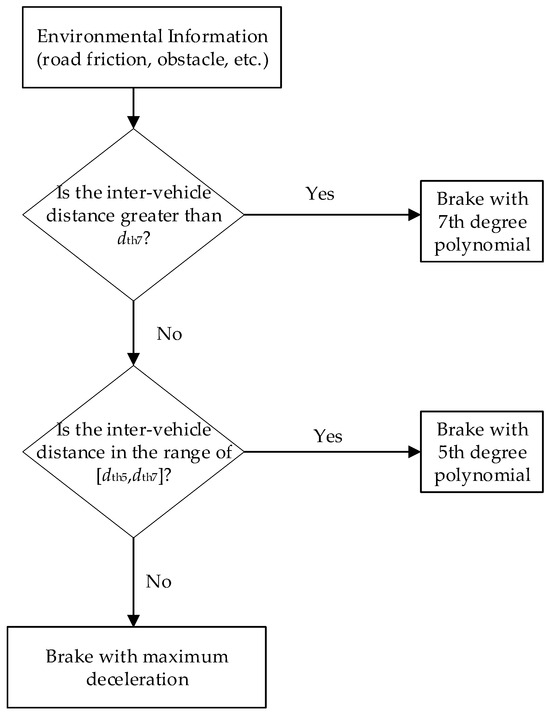
Figure 2.
Overall control framework.
3.2. Automatic Braking Using a Seventh-Degree Polynomial
We assume that the vehicle’s longitudinal displacement during braking varies as shown in Equation (1). Therefore, the expressions for the velocity, acceleration, and jerk can be written as in Equations (2)–(4).
At the moment that braking begins, the vehicle has x(0) = 0, v(0) = v0, a(0) = 0, and j(0) = 0. Similarly, at the moment that braking ends, tf, the vehicle has x(tf) = xf, v(tf) = 0, a(tf) = 0, and j(tf) = 0. By substituting the above constraints into Equations (1)–(4), we can derive Equations (5)–(9).
To ensure comfort during the braking process, the following objective function in Equation (10) must be minimized. Through calculations, the time of the vehicle’s stop, tf, can be derived as shown in Equation (11).
The maximum braking acceleration, amax, occurs at time ta, and the stopping distances, xf, are given by Equations (12) and (13). Here, xs = v02/(2amax) represents the stopping distance at maximum deceleration. It is evident that the required minimum braking distance using a seventh-degree polynomial is approximately 1.78 times that of the stopping distance at maximum deceleration and 1.25 times that of the stopping distance using a fifth-degree polynomial.
4. Simulation and Analysis
To validate the control algorithm proposed in this study, initial verification is conducted using a point mass model. Subsequently, a high-fidelity CarSim vehicle dynamics model is employed for further validation. This study assumes that the road friction is known, which can be obtained through estimation algorithms [40] or V2X communication.
4.1. Point Mass Model
The simulation analysis is conducted using a point mass vehicle model in the MATLAB/Simulink R2022a platform, with a starting speed of 60 km/h on a high-friction road (µ = 0.9). Figure 3 compares the simulation results of fifth-order polynomial braking and seventh-order polynomial braking. The blue solid line represents the fifth-order polynomial results, while the red dashed line represents the seventh-order polynomial results. Panels (a) to (d) of Figure 3 show the responses in terms of the braking distance, vehicle speed, deceleration, and jerk, respectively. Given the same constraints, the minimum stopping distance for the fifth-order polynomial is 21.9 m, while, for the seventh-order polynomial, it is 27.4 m. The braking times are 3.29 s and 3.84 s, respectively. The times to reach peak deceleration are 1.11 s for the fifth-order polynomial and 1.54 s for the seventh-order polynomial. The maximum jerk values are 1.85 g/s at t = 0 for the fifth-order polynomial and 0.92 g/s at t = 0.6 s for the seventh-order polynomial. In conclusion, although the seventh-order polynomial requires a 25% longer braking distance compared to the fifth-order polynomial, it significantly reduces the maximum jerk value by approximately 50%, thereby improving the vehicle braking comfort.
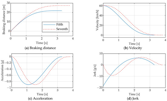
Figure 3.
Fifth-order polynomial vs. seventh-order polynomial (v = 60 km/h and µ = 0.9).
Figure 4 and Figure 5 display the simulation results for fifth-order and seventh-order polynomial braking on a high-friction road (µ = 0.9), under different initial speeds. Panels (a) to (d) in both figures show the responses of the braking distance, vehicle speed, acceleration, and jerk. It is evident that, as the initial speed increases, the required braking distances for both polynomial types also increase. The braking time increases proportionally with the initial speed, while the maximum jerk value decreases as the initial speed rises. Detailed performance metrics can be found in Table 1. When traveling at 90 km/h, the fifth-degree polynomial yields a braking distance of 49.4 m, a braking time of 4.93 s, and a maximum jerk of 1.23 g/s. In contrast, the seventh-degree polynomial results in a braking distance of 61.7 m, a braking time of 5.76 s, and a maximum jerk of 0.61 g/s. Under the same initial conditions, the braking distance for the seventh-degree polynomial is 25% greater compared to the fifth-order polynomial, while its maximum jerk value is reduced by approximately 50%. Figure 6 compares bar charts of the fifth-order and seventh-order polynomials, using an initial speed of 90 km/h as an example.
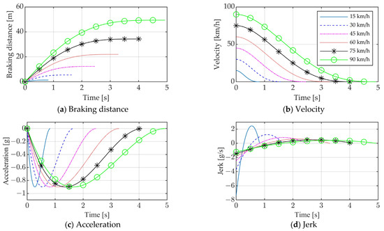
Figure 4.
Results of fifth-order polynomial planning at different initial speeds (µ = 0.9).


Figure 5.
Results of seventh-order polynomial planning at different initial speeds (µ = 0.9).

Table 1.
Comparison of results for braking at different initial speeds.
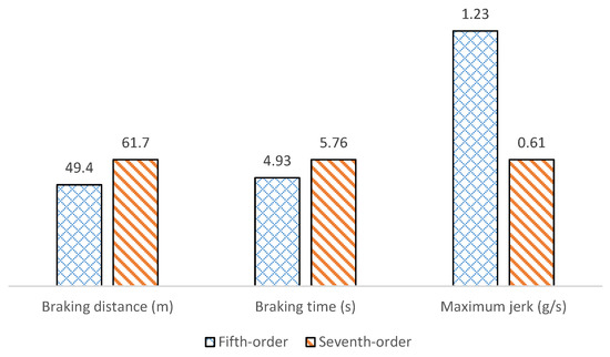
Figure 6.
Comparison of results for braking at 90 km/h initial speed (µ = 0.9).
Figure 7 presents the simulation tests under the condition of a stationary leading vehicle, starting with a distance of 150 m between the trailing and leading vehicles, and the following vehicle travels at a starting speed of 80 km/h on a high-friction road (µ = 0.9). Figure 6a–e display the responses in terms of the distance between the two cars and the speed, acceleration, jerk, and TTC of the trailing vehicle. It is evident that the vehicle equipped with a seventh-order polynomial automatic braking control system can prevent rear-end collisions effectively, maintaining a distance of approximately 2 m between the two vehicles when the following car comes to a halt. The vehicle’s braking deceleration initially increases and then decreases, reaching peak deceleration at t = 6.5 s. The following vehicle’s speed drops to zero at around t = 9.5 s. Overall, the braking process is comfortable, with smooth jerk changes featuring both troughs and peaks, reaching −0.69 g/s and 0.51 g/s at t = 5.3 s and t = 7.8 s, respectively. The TTC reaches its minimum value of 0.84 s at t = 7.2 s.
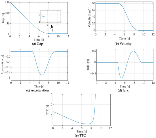
Figure 7.
Seventh-order polynomial responses (leading vehicle stationary, initial gap = 150 m, initial speed = 80 km/h, and µ = 0.9).
Figure 8 illustrates the vehicle’s response on a low-friction road (µ = 0.3), maintaining the other conditions as in Figure 6. Figure 7a–e depict the responses of the inter-vehicle distance, the following vehicle’s speed, acceleration, jerk, and TTC. As observed, the vehicle successfully avoids a collision, albeit with the earlier initiation of braking. The peak braking acceleration is attained at t = 6 s. Throughout the braking process, the peak jerk reaches approximately −0.08 g at t = 2.5 s.

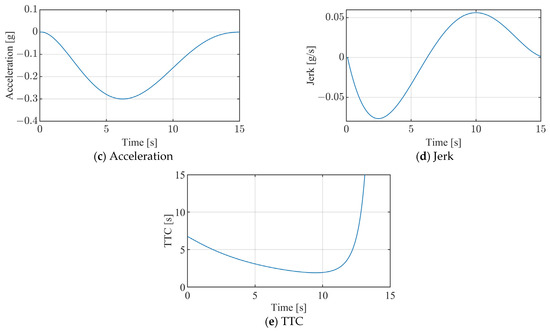
Figure 8.
Seventh-order polynomial responses (leading vehicle stationary, initial gap = 150 m, initial speed = 80 km/h, and µ = 0.3).
4.2. CarSim Model
To further confirm the efficiency of the control algorithm, a vehicle dynamics model using the CarSim software was employed for simulation testing. CarSim, developed by the Mechanical Simulation Corporation, is a mature commercial software program that is widely used in both academia and the automotive industry for vehicle dynamics simulations. The testing scenarios are according to the European New Car Assessment Programme (Euro NCAP) and include three main test conditions: car-to-car rear stationary (CCRs), car-to-car rear moving (CCRm), and car-to-car rear braking (CCRb), as detailed in Table 2. The CCRs and CCRm tests were conducted with speed increases of 5 km/h or 10 km/h within the ranges specified in Table 2. In the CCRs test condition, the leading vehicle remained stationary, while, in the CCRm scenario, the leading vehicle traveled at a speed of 20 km/h. The CCRb scenario was conducted at a constant speed of 50 km/h for both the leading and following vehicles, utilizing the combinations of 2 m/s2 and 6 m/s2 deceleration with 12 m and 40 m headway. Figure 9 illustrates the AEB testing scenario. Table 3 provides the key model parameters of the trailing vehicle.

Table 2.
CCR test scenario [41].
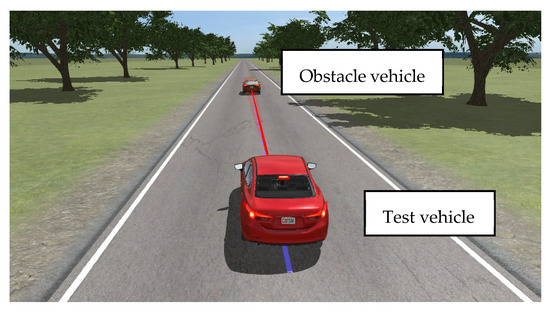
Figure 9.
AEB simulation test scenario.

Table 3.
The following vehicle’s main parameters.
4.2.1. CCRs
In the CCRs test condition, the front vehicle remains motionless while the rear vehicle runs at 80 km/h, with a starting distance of 60 m between the two vehicles above. Figure 10a–e depict the responses of the inter-vehicle distance, the trailing vehicle’s speed, the relative speed, the deceleration, and the TTC. The results indicate that the vehicle equipped with a seventh-degree polynomial automatic braking system effectively prevents rear-end collisions, with a gap of approximately 2.1 m from the leading vehicle. During braking, the vehicle’s deceleration changes smoothly, without the abrupt shifts typical of the TTC control algorithm, ensuring good comfort. However, due to the consideration of the suspension system’s characteristics, the vehicle’s pitch motion during braking causes fluctuations in the vertical tire loads, which in turn lead to variations in the wheel braking force, resulting in some oscillation in the longitudinal deceleration. Throughout the braking process, the minimum TTC recorded is 0.94 s, occurring at t = 2.9 s.

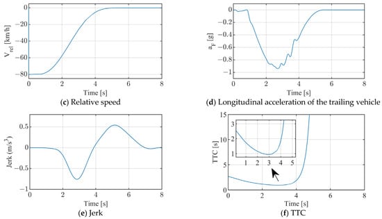
Figure 10.
CCRs scenario test results (vF = 80 km/h, vL = 0 km/h, and xr = 60 m).
4.2.2. CCRm
In the CCRm test scenario, the front vehicle travels at a fixed speed of 20 km/h, while the trailing vehicle runs at 60 km/h, maintaining an initial gap of 60 m. Figure 11a–e illustrate the responses of the inter-vehicle distance, the speed of the trailing vehicle, their relative speeds, the deceleration of the front vehicle, and the time-to-collision value. The results show that the vehicle equipped with a seventh-degree polynomial automatic braking system is also effective in preventing rear-end collisions in this scenario, with a gap of approximately 2 m from the leading vehicle. The trailing vehicle reduces its speed to match that of the front vehicle at around t = 6.5 s. The trailing vehicle’s deceleration initially increases and then decreases, reaching a peak value at around t = 5.4 s. Throughout the braking process, the minimum TTC recorded is 0.75 s, occurring at t = 5.0 s.

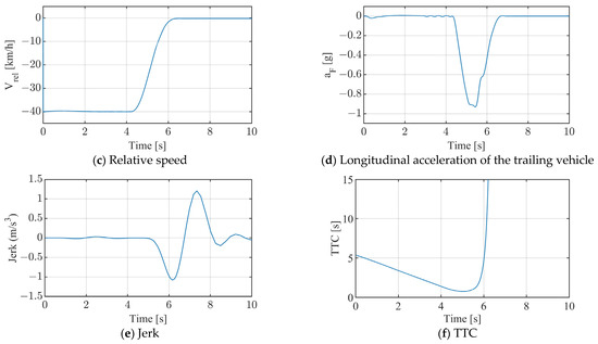
Figure 11.
CCRm scenario test results (vF = 60 km/h, vL = 20 km/h, and xr = 60 m).
4.2.3. CCRb
In the CCRb test scenario, both vehicles travel at a fixed speed of 50 km/h, with a starting distance of 12 m between them. At t = 0 s, the leading vehicle begins braking at a deceleration rate of 6 m/s2. Figure 12a–e show the responses of the inter-vehicle distance, the speed of the trailing vehicle, their relative speeds, the deceleration of the following vehicle, and the TTC. The test results indicate that the following vehicle can also effectively prevent a crash in this scenario, stopping approximately 2.07 m from the front vehicle. The trailing vehicle’s speed drops to zero at t = 3.5 s. Similar to the previous scenarios, the following vehicle’s deceleration first increases and then decreases, reaching a peak at t = 1.9 s. Throughout the braking process, the minimum TTC recorded is 1.06 s, occurring at t = 2.32 s.

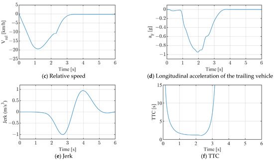
Figure 12.
CCRb scenario test results (vF = 50 km/h, vL = 50 km/h, and aL = −6 m/s2).
5. Discussion
The braking system has become a vital safety feature in modern vehicles, significantly aiding in the reduction of rear-end collisions. Braking control algorithms primarily face two critical challenges: determining when to apply the brakes and optimizing the braking force. The timing of brake engagement is crucial; if the system responds too late, a collision may occur, while premature activation can cause unnecessary discomfort for passengers and potentially trigger rear-end collisions from following vehicles. Researchers are increasingly focused on integrating drivers’ risk perception into braking systems, recognizing that understanding a driver’s situational awareness can enhance decision-making processes.
The relationship between the time to collision and driver behavior is critical. Drivers perceive their distance to the vehicle ahead based on the TTC. By incorporating this perception into braking control algorithms, the system can be fine-tuned to align more closely with human intuition, resulting in smoother and more effective braking maneuvers.
A key consideration in automatic braking control is the balance between safety and comfort. While maximizing safety is essential, sudden and harsh braking can lead to discomfort and panic among passengers. Therefore, automatic braking control systems must be designed to ensure that braking actions are gradual and proportional to the perceived risk.
Existing research primarily employs time-to-collision models and safe distance models or builds upon them to enhance the control algorithms. While these algorithms can effectively prevent collisions, sudden braking can significantly impact passenger comfort. Although leveraging the braking behavior of professional drivers is an effective way to improve vehicle safety and occupant comfort, modeling and validating such behavior is a complex process. This study adopts a different control approach by transforming the automatic braking collision avoidance problem into a trajectory planning problem, offering a new perspective for braking control. The advantage of this control method lies in its ability to consider constraints both before and after braking, allowing for effective collision avoidance while simultaneously enhancing passenger comfort.
The analysis reveals that, under the same initial speed, the braking distance required by the seventh-order polynomial braking algorithm is the longest, being 1.25 times that of the fifth-order polynomial and 1.78 times that of maximum-deceleration braking. Nevertheless, the seventh-order polynomial significantly improves the braking comfort, with the peak jerk reduced by approximately 50% compared to the fifth-order polynomial. For example, when braking at an initial speed of 90 km/h on a road surface with a friction coefficient of 0.9, the seventh-order polynomial requires a braking distance of 61.7 m, a braking time of 5.76 s, and a maximum jerk of 0.61 g/s. In contrast, the fifth-order polynomial requires a braking distance of 49.4 m, a braking time of 4.93 s, and a maximum jerk of 1.23 g/s. The simulation results from both the point mass model and the CarSim dynamic model confirm the effectiveness of the seventh-order polynomial braking algorithm.
Thus, when a sufficient braking distance is available, a comfort-oriented control algorithm, such as the proposed seventh-order polynomial braking algorithm, can be employed, rather than relying on abrupt braking at close range. The proposed algorithm is not limited to emergency braking but is applicable to all braking scenarios. It offers valuable insights into scenarios where a vehicle gradually approaches an obstacle from a distance.
However, it is worth noting that, in emergency situations where obstacles appear suddenly at close range, the seventh-order polynomial may not be the optimal choice. In such cases, avoiding a collision takes precedence over comfort, necessitating the use of braking algorithms with shorter stopping distances, such as time-to-collision (TTC) control or maximum-deceleration braking.
6. Conclusions
This study proposes a vehicle automatic deceleration control method based on a seventh-degree polynomial, which balances safety and comfort during the braking procedure. The control strategy takes into account the constraints at the start and end of braking, allowing for a smooth change in deceleration, significantly enhancing the braking comfort. Compared to constant maximum-deceleration braking and fifth-degree polynomial braking, the braking distance and time of the seventh-degree polynomial method are slightly increased. Under the same initial conditions, its braking distance is approximately 1.78 times that of constant maximum-deceleration braking and 1.25 times that of fifth-degree polynomial braking. The braking time is about 2.07 times longer than that of constant maximum-deceleration braking and 1.17 times longer than that of fifth-degree polynomial braking. However, the braking comfort is markedly improved under the same initial conditions, with the maximum jerk value during braking reduced by about 50% compared to the fifth-degree polynomial method. Simulation tests using CCR scenarios also demonstrate the effectiveness of this control algorithm. The suggested control approach is expected to promote the widespread adoption of intelligent connected vehicles and autonomous driving technologies. Currently, the validation of the control algorithm is based solely on simulations; future work will involve real-vehicle testing for further verification. The impact of varying vehicle masses on control algorithms warrants further investigation. Additionally, research on control algorithms should also address complex road conditions, such as roads with uneven friction coefficients and curved roadways. Investigating the braking demands of drivers with different driving styles in control algorithms is also a valuable area of research.
Author Contributions
Conceptualization, F.L.; methodology, formal analysis, F.L. and C.H.; software, validation, F.L.; writing, F.L. and C.H.; supervision, project administration, F.L. All authors have read and agreed to the published version of the manuscript.
Funding
This work was supported by the National Natural Science Foundation of China (NSFC) Project (52472400), the Chongqing Natural Science Foundation Project (CSTB2024NSCQ-MSX0493), and the Science and Technology Research Program of Chongqing Education Commission of China (KJZD-K202404001).
Data Availability Statement
Data are contained within the article.
Conflicts of Interest
The authors declare no conflicts of interest.
References
- Fildes, B.; Keall, M.; Bos, N.; Lie, A.; Page, Y.; Pastor, C.; Pennisi, L.; Rizzi, M.; Thomas, P.; Tingvall, C. Effectiveness of Low Speed Autonomous Emergency Braking in Real-World Rear-End Crashes. Accid. Anal. Prev. 2015, 81, 24–29. [Google Scholar] [CrossRef] [PubMed]
- Haus, S.H.; Sherony, R.; Gabler, H.C. Estimated Benefit of Automated Emergency Braking Systems for Vehicle-Pedestrian Crashes in the United States. Traffic Inj. Prev. 2019, 20, 171–176. [Google Scholar] [CrossRef] [PubMed]
- Cicchino, J.B.; Zuby, D.S. Characteristics of Rear-End Crashes Involving Passenger Vehicles with Automatic Emergency Braking. Traffic Inj. Prev. 2019, 20, 112–118. [Google Scholar] [CrossRef] [PubMed]
- Kidd, D.G. Improving the Safety Relevance of Automatic Emergency Braking Testing Programs: An Examination of Common Characteristics of Police-reported Rear-End Crashes in the United States. Traffic Inj. Prev. 2022, 23, 137–142. [Google Scholar] [CrossRef] [PubMed]
- Eichelberger, A.; Mccartt, A. Volvo Drivers’ Experiences with Advanced Crash Avoidance and Related Technologies. Traffic Inj. Prev. 2014, 15, 187–195. [Google Scholar] [CrossRef]
- Vandiver, W.; Anderson, R. Performance of the Ford Pre-Collision Assist with Automatic Emergency Braking System in Instrumented Tests; SAE Technical Paper 2021-01-0894; SAE International: Warrendale PA, USA, 2021. [Google Scholar] [CrossRef]
- Miholjcic, D.; Fabbroni, M.; Robinson, R. A Study of the Performance of Automatic Emergency Braking (AEB) Systems Equipped on Passenger Vehicles for Model Years 2013 to 2018; SAE Technical Paper 2019-01-0416; SAE International: Warrendale PA, USA, 2019. [Google Scholar] [CrossRef]
- Soule, H.; Davis, A.; Krum, A. Risk Mitigation Planning for Revenue Service Testing of Bus Automated Emergency Braking. Transp. Res. Rec. 2021, 2675, 193–200. [Google Scholar] [CrossRef]
- Salaani, M.; Elsasser, D.; Boday, C. Heavy Vehicles Kinematics of Automatic Emergency Braking Test Track Scenarios; SAE Technical Paper 2020-01-0995; SAE International: Warrendale PA, USA, 2020. [Google Scholar] [CrossRef]
- Li, S.; Wang, G.; Wang, H. Automatic Emergency Braking/Anti-lock Braking System Coordinated Control with Road Adhesion Coefficient Estimation for Heavy Vehicle. IET Intell. Transp. Syst. 2022, 16, 1521–1534. [Google Scholar] [CrossRef]
- Liu, Y.; Ball, J.; Abdelwahed, S.; He, G. An Automatic Emergency Braking System for Collision Avoidance Assist of Multi-Trailer Vehicle Based on Model Prediction Control; SAE Technical Paper 2021-01-0117; SAE International: Warrendale PA, USA, 2021. [Google Scholar] [CrossRef]
- Mimura, Y.; Ando, R.; Higuchi, K.; Yang, J. Recognition on Trigger Condition of Autonomous Emergency Braking System. J. Saf. Res. 2020, 72, 239–247. [Google Scholar] [CrossRef]
- Diederich, A.; Bastien, C.; Blundell, M. The Prediction of Autonomous Vehicle Occupants’ Pre-crash Motion during Emergency Braking Scenarios. Proc. Inst. Mech. Eng. Part D J. Automob. Eng. 2023, 237, 3304–3312. [Google Scholar] [CrossRef]
- Lee, D. A Theory of Visual Control of Braking Based on Information about Time-to-Collision. Perception 1976, 5, 437–459. [Google Scholar] [CrossRef]
- Kondoh, T.; Yamamura, T.; Kitazaki, S. Identification of Visual Cues and Quantification of Drivers’ Perception of Proximity Risk to the Lead Vehicle in Car-Following Situations. J. Mech. Syst. Transp. Logist. 2008, 1, 170–180. [Google Scholar] [CrossRef]
- Kitajima, S.; Marumo, Y.; Hiraoka, T.; Itoh, M. Comparison of Evaluation Indices Concerning Estimation of Driver’s Risk Perception—Risk Perception of Rear-End Collision to a Preceding Vehicle. Rev. Automot. Eng. 2009, 30, 191–198. [Google Scholar]
- Kondoh, T.; Furuyama, N.; Hirose, T.; Sawada, T. Direct Evidence of the Inverse of TTC Hypothesis for Driver’s Perception in Car-Closing Situations. Int. J. Automot. Eng. 2014, 5, 121–128. [Google Scholar] [CrossRef] [PubMed]
- Hiraoka, T.; Takada, S. Improvement of Evaluation Indices for Rear-End Collision Risk. IEEE Trans. Hum.-Mach. Syst. 2018, 48, 102–109. [Google Scholar] [CrossRef]
- Kilicarslan, M.; Zheng, J. Predict Vehicle Collision by TTC Form Motion Using a Single Video Camera. IEEE Trans. Intell. Transp. Syst. 2019, 20, 522–533. [Google Scholar] [CrossRef]
- Wang, Z.; Zang, L.; Jiao, J.; Mao, Y. Research on Hierarchical Control Strategy of Automatic Emergency Braking System. World Electr. Veh. J. 2023, 14, 97. [Google Scholar] [CrossRef]
- Doi, A.; Butsuen, T.; Niibe, T.; Takagi, T.; Yamamoto, Y.; Seni, H. Development of a Rear-End Collision Avoidance System with Automatic Brake Control. JSAE Rev. 1994, 15, 335–340. [Google Scholar] [CrossRef]
- Seiler, P.; Song, B.; Hedrick, J. Development of a Collision Avoidance System; SAE Technical Paper 980853; SAE International: Warrendale PA, USA, 1998. [Google Scholar] [CrossRef]
- Ro, J.; Roop, P.; Malik, A. A New Safety Distance Calculation for Rear-End Collision Avoidance. IEEE Trans. Intell. Transp. Syst. 2021, 22, 1742–1747. [Google Scholar] [CrossRef]
- Gounis, K.; Bassiliades, N. Intelligent Momentary Assisted Control for Autonomous Emergency Braking. Simul. Model. Pract. Theory 2022, 115, 102450. [Google Scholar] [CrossRef]
- Fu, X.; Wan, J.; Wu, D.; Jiang, W.; Ma, W.; Yang, T. Research on Vehicle AEB Control Strategy Based on Safety Time–Safety Distance Fusion Algorithm. Mathematics 2024, 12, 1905. [Google Scholar] [CrossRef]
- Koglbauer, I.; Holzinger, J.; Eichberger, A.; Lex, C. Autonomous Emergency Braking Systems Adapted to Snowy Road Conditions Improve Drivers’ Perceived Safety and Trust. Traffic Inj. Prev. 2018, 19, 332–337. [Google Scholar] [CrossRef] [PubMed]
- Bae, J.; Lee, M.; Kang, N. Partial and Full Braking Algorithm According to Time-to-Collision for Both Safety and Ride Comfort in an Autonomous Vehicle. Int. J. Automot. Technol. 2020, 21, 351–360. [Google Scholar] [CrossRef]
- Han, S.; Choi, K.; Kim, K. Adaptive Safety Distance for Collision Avoidance Based on a Full Braking Activation Parameter. IEEE Trans. Intell. Transp. Syst. 2024, 25, 12657–12668. [Google Scholar] [CrossRef]
- Wada, T.; Hiraoka, S.; Doi, S. A Control Method of Deceleration Assistance System for Collision Avoidance Based on Driver’s Perceptual Risk. Ind. Robot: Int. J. 2010, 37, 347–353. [Google Scholar] [CrossRef]
- Lai, F.; Huang, C. A Study on Automatic Emergency Braking Control Algorithm Based on Professional Drivers’ Braking Behavior. SAE Int. J. Connect. Autom. Veh. 2023, 6, 139–154. [Google Scholar] [CrossRef]
- Lai, F.; Liu, J.; Hu, Y. An Automatic Emergency Braking Control Method for Improving Ride Comfort. World Electr. Veh. J. 2024, 15, 259. [Google Scholar] [CrossRef]
- Lai, F.; Huang, C.; Jiang, C. When and How to Apply Automatic Emergency Brakes Based on Risk Perception and Professional Driver Emergency Braking Behavior. SAE Int. J. Veh. Dyn. Stab. NVH 2023, 7, 421–436. [Google Scholar] [CrossRef]
- Thunberg, J.; Bischoff, D.; Schiegg, F.A.; Meuser, T.; Vinel, A. Unreliable V2X Communication in Cooperative Driving: Safety Times for Emergency Braking. IEEE Access 2021, 9, 148024–148036. [Google Scholar] [CrossRef]
- Sidorenko, G.; Thunberg, J.; Sjöberg, K.; Fedorov, A.; Vinel, A. Safety of Automatic Emergency Braking in Platooning. IEEE Trans. Veh. Technol. 2022, 71, 2319–2332. [Google Scholar] [CrossRef]
- Sidorenko, G.; Plöger, D.; Thunberg, J.; Vinel, A. Emergency Braking with ACC: How Much Does V2V Communication Help? IEEE Netw. Lett. 2022, 4, 157–161. [Google Scholar] [CrossRef]
- Singh, A.S.P.; Nishihara, O. Trajectory Tracking and Integrated Chassis Control for Obstacle Avoidance with Minimum Jerk. IEEE Trans. Intell. Transp. Syst. 2022, 23, 4625–4641. [Google Scholar] [CrossRef]
- Kim, D.; Nguyen, H.; Han, K. State-Constrained Lane Change Trajectory Planning for Emergency Steering on Slippery Roads. IEEE Trans. Veh. Technol. 2023, 72, 8553–8565. [Google Scholar] [CrossRef]
- Li, J.; Chen, C.; Ren, H. Time-Optimal Trajectory Planning and Tracking for Autonomous Vehicles. Sensors 2024, 24, 3281. [Google Scholar] [CrossRef] [PubMed]
- Yacoub, M.; Antkiewicz, M.; Czarnecki, K.; McPhee, J. Gain-scheduled Model Predictive Controller for Vehicle-Following Trajectory Generation for Autonomous Vehicles. Veh. Syst. Dyn. 2024, 1–26. [Google Scholar] [CrossRef]
- Chen, T.; Cai, Y.; Chen, L.; Xu, X. Sideslip Angle Fusion Estimation Method of Three-Axis Autonomous Vehicle Based on Composite Model and Adaptive Cubature Kalman Filter. IEEE Trans. Transp. Electrif. 2024, 10, 316–330. [Google Scholar] [CrossRef]
- European New Car Assessment Programme (Euro NCAP). Test Protocol–AEB Systems. Available online: https://cdn.euroncap.com/media/17719/euro-ncap-aeb-test-protocol-v11.pdf (accessed on 21 October 2021).
Disclaimer/Publisher’s Note: The statements, opinions and data contained in all publications are solely those of the individual author(s) and contributor(s) and not of MDPI and/or the editor(s). MDPI and/or the editor(s) disclaim responsibility for any injury to people or property resulting from any ideas, methods, instructions or products referred to in the content. |
© 2024 by the authors. Licensee MDPI, Basel, Switzerland. This article is an open access article distributed under the terms and conditions of the Creative Commons Attribution (CC BY) license (https://creativecommons.org/licenses/by/4.0/).