Abstract
In the current paper, an iterative algorithm is developed to simulate the problem of two-phase flow with heat transfer in porous media. The convective body force caused by heat transfer is described by Boussinesq approximation throughout with the governing equations, namely, pressure, saturation, and energy. The two coupled equations of pressure and saturation are solved using the implicit pressure-explicit saturation (IMPES) scheme, while the energy equation is treated implicitly, and the scheme is called iterative implicit pressure, explicit saturation, implicit temperature (I-IMPES-IMT). In order to calculate the pressure implicitly, the equations of pressure and saturation are coupled by linearizing the capillary pressure which is a function of saturation. After that, the equation of saturation is solved explicitly. Then, the velocity is computed which is used in the energy equation to calculate the temperature implicitly. The cell-centered finite difference (CCFD) method is utilized for spatial discretization. Furthermore, a relaxation factor along is used with the Courant–Friedrichs–Lewy (CFL) condition. Finally, in order to illustrate the efficiency of the developed algorithm, error estimates for saturation and temperature for different values of time steps and number of iterations are presented. Moreover, numerical examples of different physical scenarios of heterogamous media are presented.
1. Introduction
In the reservoir simulation, there are two numerical methods for solving the governing equations, namely, implicit pressure, explicit saturation (IMPES) method, and the fully implicit method. For each cell, the solution of these equations provides a way to estimate specific time-dependent changes in pressure, saturation, and other key parameters. Although IMPES is much faster than the fully implicit method, it is much less stable because of the explicit evaluation of mobility terms and capillary pressure at the previous time step n instead of the current one which requires smaller time steps. On the other hand, as more equations have to be solved in the fully implicit scheme, it requires more CPU memory. Since the fully implicit method is more stable than IMPES, the simulator can take bigger time steps. The ongoing research into IMPES mainly focuses on the improvement of its stability (such as using iterative schemes) and so keeping it fast and robust. The model of two-phase flow in porous media can be solved numerically using a fully implicit scheme [1,2,3], or using an implicit-explicit (IMEX) one [4,5]. The implicit schemes are unconditionally stable but they are time-consuming and expensive from a computational point of view. Therefore, despite IMEX schemes being conditionally stable, they are usually chosen to solve large-scale systems such as oil reservoir models using the IMPES approach. The IMPES schemes have been improved many times (e.g., [6,7]).
The iterative IMPES method is considered to be one of the improved versions of IMPES for two-phase flow [8,9,10]. The IMPES approach divides the system of the equation into the pressure equation and saturation equation which are solved sequentially. Iterative IMPES uses IMPES instead of Newton iteration as an iterative scheme for full implicit systems. In some iterative schemes [11,12], the pressure equation is implicitly solved and for each iteration, an implicit saturation equation with the implicit capillary pressure is constructed and solved. The iterative method was used along with the IMPES scheme by Kou and Sun [13] and El-Amin et al. [14]. In [13], an iterative version of the IMPES scheme was introduced. Kou and Sun [13] linearized the capillary pressure function to be used to couple the implicit saturation equation into the implicit pressure equation. In [14], an iterative implicit pressure, explicit saturation, implicit concentration scheme was developed to solve the model of nanoparticle transport with two-phase flow in porous media.The linearized capillary pressure function was also used to couple the implicit saturation and pressure equations, while the concentration equations were treated implicitly. Recently, El-Amin et al. [15] introduced a convergence analysis of the nonlinear iterative method for two-phase flow and nanoparticle transport in porous media.
The non-isothermal two-phase flow in porous media appears in many natural and industrial applications such as steam injection in oil recovery, geothermal reservoirs, and other environmental and engineering applications [16,17,18].
In the current work, we develop an iterative implicit pressure, explicit saturation, implicit temperature (I-IMPES-IMT) scheme to simulate the problem of non-isothermal two-phase flow in porous media. To the best of the author’s knowledge, no research develops a similar scheme to simulate the non-isothermal two-phase flow in porous media. The remaining sections of this paper are arranged as follows: in Section 2, we develop a mathematical model consisting of a group of differential equations, algebraic constraints, and initial/boundary conditions. Then, in Section 3, we introduce an iterative scheme for the governing equation. The spatial discretization is presented in Section 4. In Section 5, error estimation and solution verification are discussed and some numerical examples are listed. Finally, the conclusion is drawn in Section 6.
2. Modeling and Mathematical Formulation
Consider the problem of two-phase flow with convective heat transfer in heterogeneous porous media. The flow is assumed to be incompressible and immiscible without phase transition. The variation in density is caused by differences in temperature and is related to the buoyancy effect which is described by the Boussinesq approximation. The basis of this approximation is that there are flows in which the temperature varies slightly, in these, the density varies slightly, and this buoyancy contributes the motion. Therefore, the variation in density is neglected anywhere except in the buoyancy term. Let be a reference density of the phase , the temperature is . For small temperature difference we can write
where is a reference density of the phase . is the coefficient of volume expansion. is in the range 10−3–10−4. For a temperature variation of moderate amount, we have
Thus, the variation in the density and therefore in the specific volume is negligible.
The velocity equation of the phase is obtained by Darcy’s law,
where is the relative permeability of the phase ; is the permeability tensor; is the -fluid viscosity; is the phase- pressure; g is the gravitational acceleration; z is the depth; is the external mass flow rate; w refers to the wetting phase; and n refers to the non-wetting phase. The temperature difference may cause a convective flow, which is represented by the Boussinesq approximation in the body force term of the previous Equation (1).
For measures of central tendency (mean, mode, median), pore-throat sizes (diameters) are generally greater than 2 mm in conventional reservoir rocks, they range from about 2 to 0.03 mm in tight-gas sandstones, and range from 0.1 to 0.005 mm in shales [19]. On the other hand, the ratio between the inertial forces and the viscous forces driving the flow is computed by the Reynolds number, which is used as a criterion to distinguish between the laminar flow, the turbulent flow, and the transition zone. For porous media, the Reynolds number is defined as , where is the injection velocity and is the injection width of the inlet. According to Bear [20], Darcy’s law, which supposes a laminar flow, is valid for Reynolds number less than 1, but the upper limit can be extended up to 10. This may be because the Reynolds number is calculated based on the discharge (inlet) flow rate, however, the velocity reduces significantly in the porous media as it depends on the permeability. For the current problem, the Reynolds number is about 0.6–1.8 for the injected water depending on the discharge inlet diameter 0.01–0.03 m. Therefore, based on Bear’s classification, Darcy’s law is valid for our study. Moreover, according to Bear’s classification, the nonlinear effects are taken into consideration for 10 < Re < 100 [20]. The flow in the current problem is linear, therefore, no need to consider the Brinkman and Forchheimer effects.
The saturation equation which represents the mass conservation law can be written as
where [–] is the porosity, and is the saturation of the phase . If we sum the two equations of saturation, (2), namely, and , whilst implementing the constraint , we reach the following pressure equation
where is the total velocity; is the capillary pressure; is the density difference; is the phase mobility; is the total mobility; and is the total source mass transfer. Equation (3) with the following saturation equation are solved simultaneously to compute the pressure of water phase:
Therefore, we can update the saturation using the following equation:
where is the flow fraction, and .
The relative permeability of the two phases is defined as
where is the normalized wetting phase saturation, such that, is the residual non-wetting saturation, is the irreducible saturation, . In addition, .
Assume that the two fluid phases and the solid phase are of local thermal equilibrium of low flow velocities and relatively small grain sizes (cf. Hassanizadeh [21]):
This yields the conservation equation of energy for a two-phase system, consisting of a solid phase plus fluid phases [16,22]:
where [kg/m3] is density of the solid phase; [kg/m3] is the heat capacity of the solid phase; [J/Kg·K] is the heat capacity of the fluid phase ; T [K] is the temperature; [m3/s] is the heat source term; is the tortuosity of the water phase; and [J/K·m·s] is the thermal conductivity of the solid phase. The thermal conductivity of the phase is expressed as
where is the deterministic thermal conductivity of the phase , while the mechanical thermal-dispersion tensor, , may be written as
Therefore,
where is the longitudinal dispersion coefficient and is the transverse dispersion coefficient.
The capillary pressure is defined by
where is the entry pressure which is a function of temperature [23],
such that
is the surface tension.
The initial and boundary conditions are given by
where is the computational domain; is the Dirichlet boundary; is the Neumann boundary, such that . is the outward unit normal vector to the boundary; is the pressure on ; and the inflow rate on .
3. Iterative Method
The governing Equations (3)–(6), are strongly coupled and highly nonlinear. In order to treat such a type of complexity, we may use an iterative method [24]. The time interval is discretized into a number of time steps, , refers to the current time step, and n refers to the previous time step. Apply iterations of iterations for each time step, such that refers to the current iteration step and k refers to the previous iteration step. The time discretization of time derivatives is achieved by using the backward Euler. The discretized pressure equation takes the form
The capillary pressure is linearized as
Using the saturation equation to find
The above three equations are solved to compute the wetting phase pressure. Then, saturation is updated using the explicit equation
where
In the above equation, the advection term is multiplied with the relaxation factor, . In order to ensure the stability of the proposed scheme, we employ the stability Courant–Friedrichs–Lewy (CFL) condition (CFL < 1) to estimate a relaxation factor. The convection terms in the discretized saturation and temperature equations are multiplied by the following relaxation factor:
The energy equation is computed implicitly by the following scheme:
where
The advection term in the energy Equation (17) is also multiplied by the relaxation factor, . Finally, the variables, ,,, , and , are updated. This procedure is repeated until approaching convergence.
4. Spatial Discretization
The cell-centered finite difference (CCFD) is a type of finite volume method and is locally conservative. In the case of rectangular elements, it was proven early on by Wheeler and Yotov [25] and Arbogast et al. [26] to be equivalent to the mixed finite element method. In the CCFD method, the velocity is located on the edges, while the pressure and permeability in the cell centers. Now, we apply the CCFD scheme to the system of Equations (13)–(17), to obtain the full implicit iterative discretization. The discretization form of the pressure equation may be given as
In the above equation, the two matrices, and , depend on the vectors and from the previous iteration step. On the other hand, the matrix depends only on the vector from the previous iteration step. Moreover, the capillary pressure approximation (14) can be discretized as
such that the matrix is diagonally defined, for total number of cells, by
It is clear that the derivative of is a function of itself, as the saturation at each spatial point varies with time even though it is discontinuously distributed in space.
The spatial discretization of the saturation equation to be coupled with the pressure equation given as
such that is a diagonal matrix appearing from the porosity coefficient. The coupled pressure equation can be obtained from substituting (20) and (21) into (19), i.e.,
where
and
The upwind scheme is used to treat the convection term of Equation (16) to obtain
Then, update i.e., to be used in the energy Equation (17),
5. Numerical Investigations
In this section, we present error estimations for the time dependent variables, and introduce two numerical examples to check the validity and the efficiency of the proposed scheme. The rate of injection on the inlet boundary is used to calculate the normal velocity, (PVI), here PVI is the pore volume injection and is inlet diameter. Table 1 shows the physical parameters definitions and values.

Table 1.
Values of the physical parameters.
The error estimates for saturation and temperature are presented in Table 2 for different values of the time steps number (TSN) and iterations number (ITN). A domain of size 1.0 × 0.5 m discretized by 40 × 30 is used in this error estimation. Non-iterative calculations are carried out at 2000, 1000, 500, and 100 time steps. In addition, we carried out some calculations for 10, 30, and 50 iterations with 100 time steps. As there is no exact solution for such a complicated problem, we created a reference case of highly dense mesh and a very small time step which is very close to the exact solution. It is under the same conditions but as mentioned above the non-iterative case is just a reference. Table 2 illustrates that the error deceases as the number of time steps and number of iterations increase. It is also clear that the temperature converges faster than saturation.

Table 2.
Error estimates for different values of the time steps number (TSN) and iterations number (ITN).
Moreover, in Table 3, the comparison of error estimates of saturation with a previous work [15] are presented for 40 × 30 of spatial discretization. The reference case is calculated at the point (0.06, 0.053) for non-iterative dense mesh of 200 × 150 for the domain 0.6 × 0.4 m over a total of 2000 time steps. The iterative case is taken after 100 time steps without iteration (ITN = 1), at ITN = 10, and ITN = 30. The comparison shows a good agreement.

Table 3.
Comparison of error estimates of saturation with a previous work.
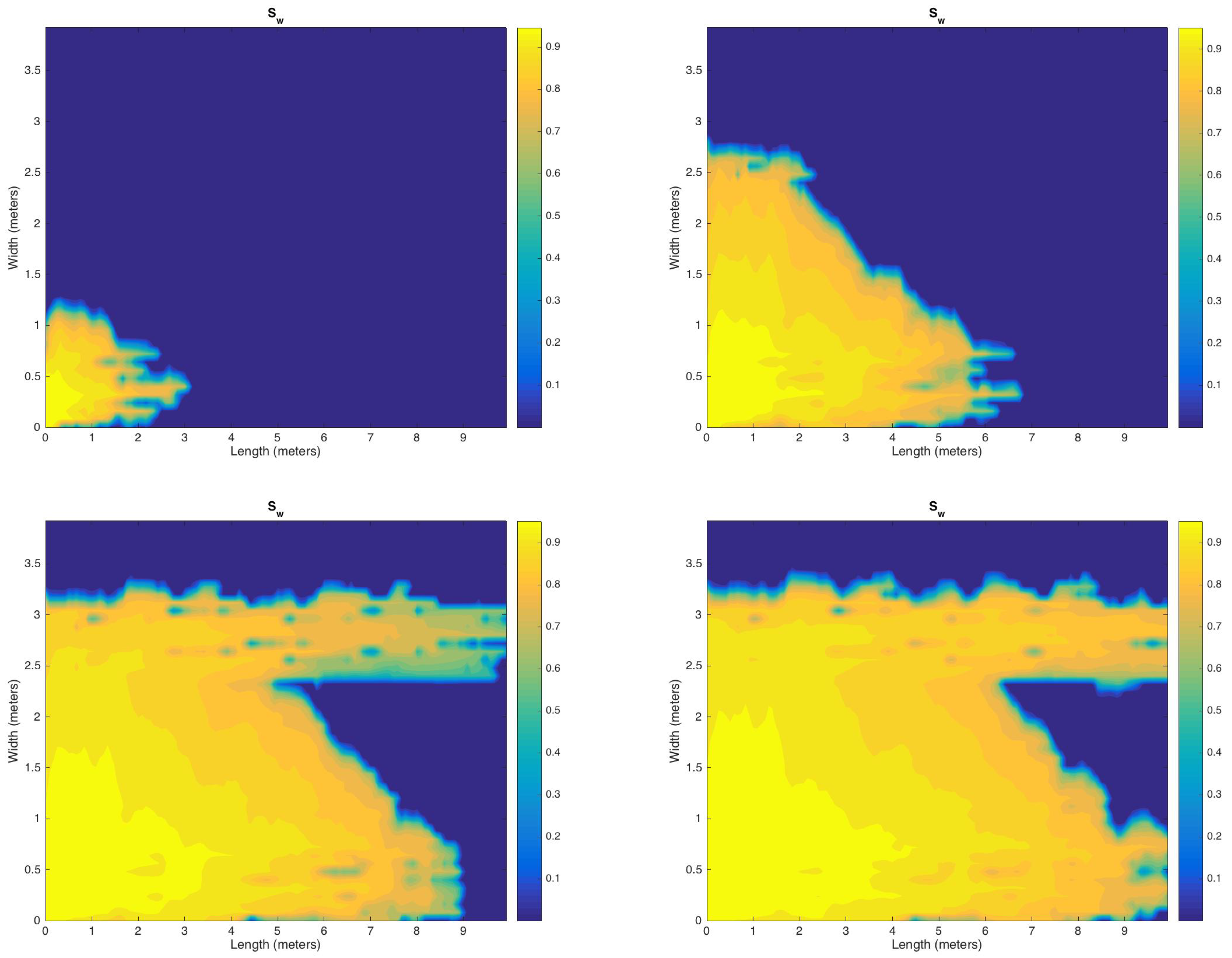
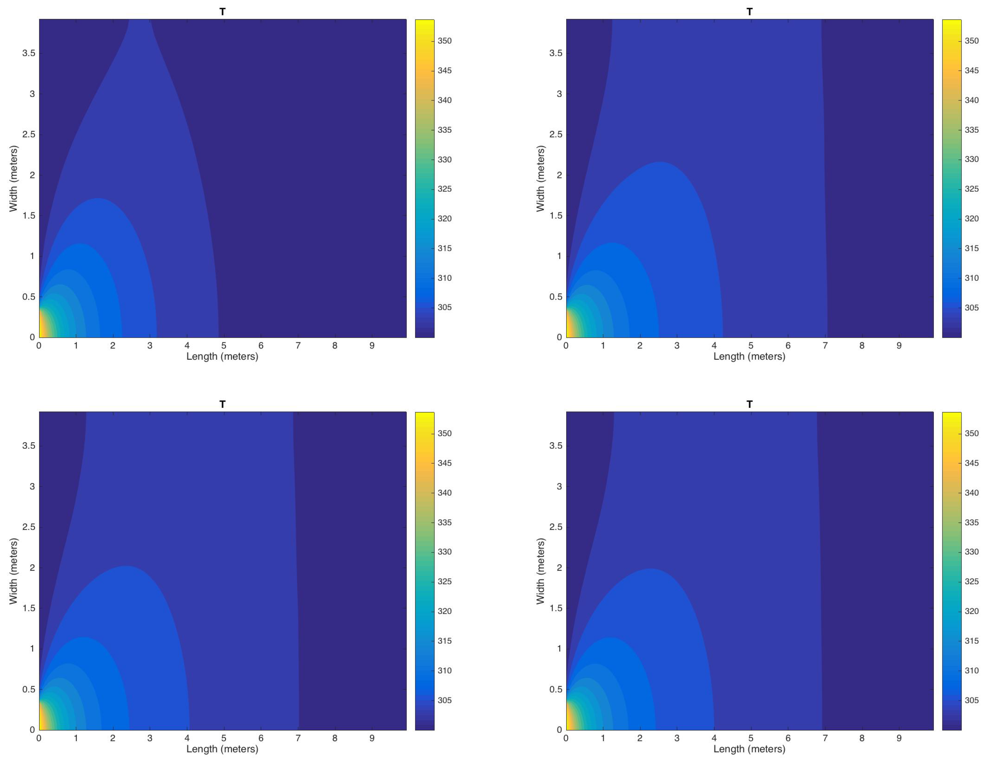
In the following, two examples are provided and discussed for heterogeneous media. The first example is a real field high-heterogeneous permeability media [27]. The spatial discretization is taken as of a uniform rectangular mesh. A hot wetting fluid is injecting at a flow rate of 0.1 pore volume injection (PVI) into the left bottom corner of the domain. Four cases of injections are taken into consideration, i.e., continue until reaches 0.35, 0.5, 0.75, and 0.85 PV (pore volume). In this example, we used a time step size of 0.01 and a maximum number of iterations of 50. Figure 1 shows the contours of the saturation of the wetting phase after 0.35, 0.5, 0.75, and 0.85 PV. It is interesting to observe discontinuities in the saturation distribution caused by the heterogeneity. Moreover, the contours of temperature at the heterogenous medium are plotted in Figure 2. It seems to be that the heterogeneity of the medium has no effect on the temperature distribution.
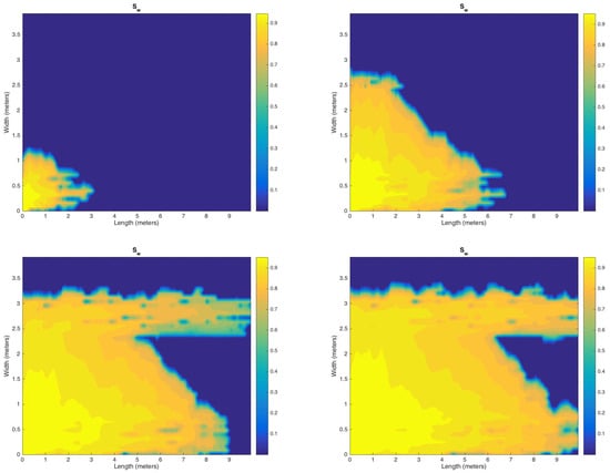
Figure 1.
Distribution of the saturation on heterogenous permeability map after 0.35, 0.5, 0.75, and 0.85 pore volume (PV).
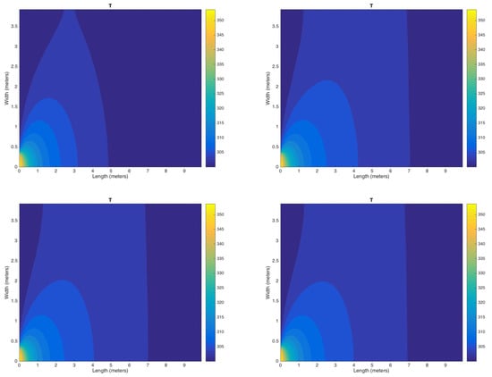
Figure 2.
Distribution of the temperature on heterogenous permeability map after 0.35, 0.5, 0.75, and 0.85 PV.
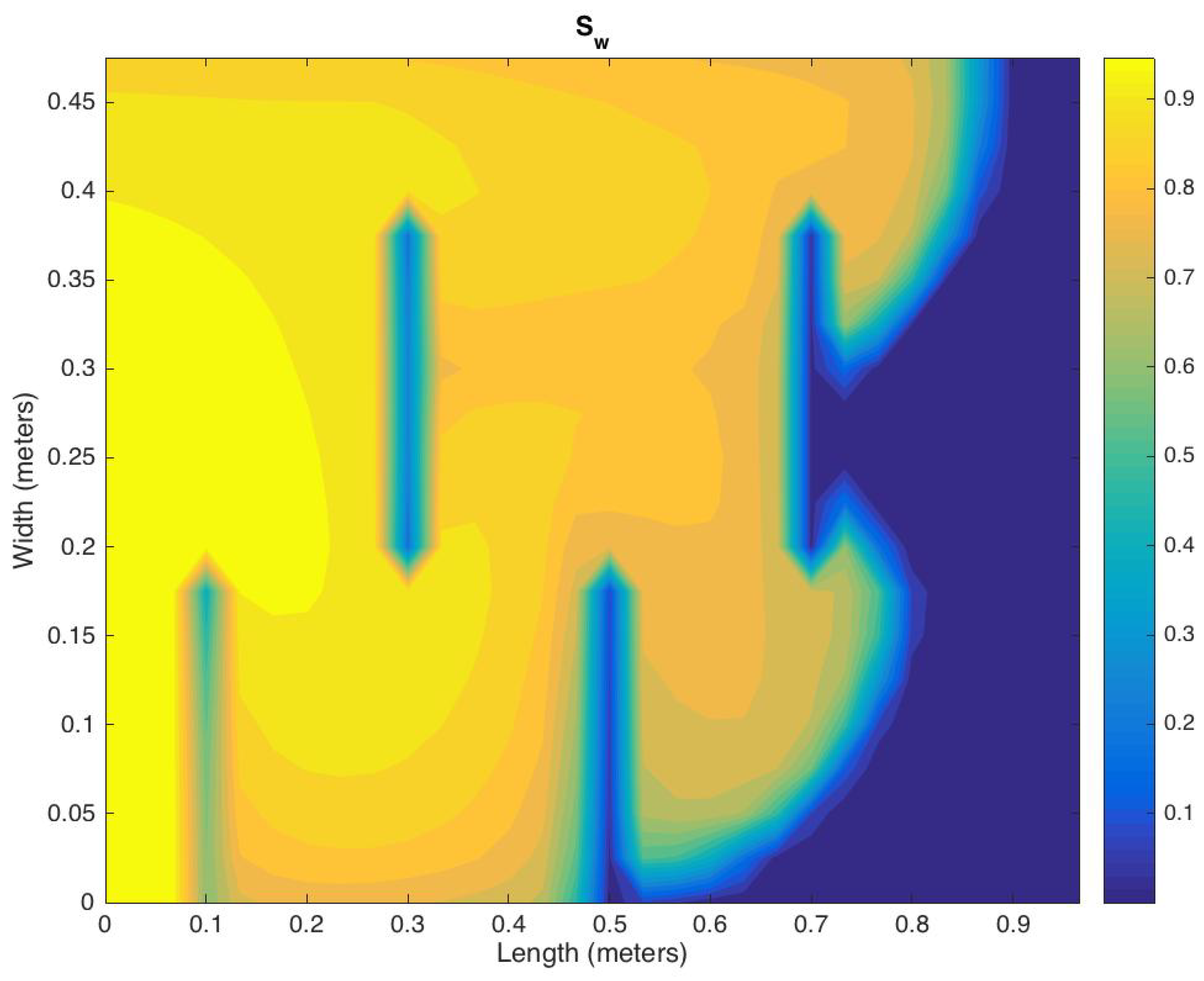
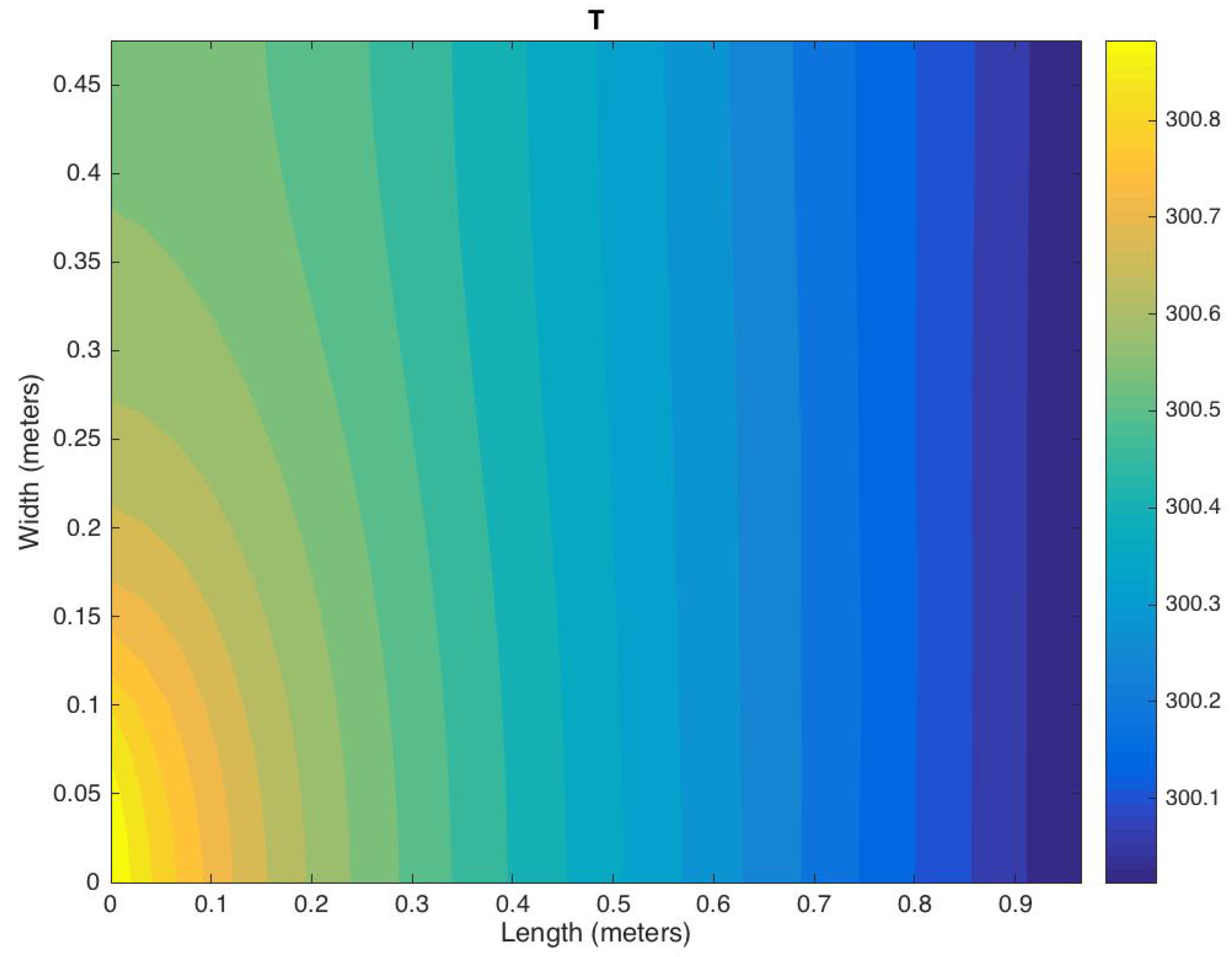
In the second example, the medium is artificial and heterogeneous, such that the it consists of two subdomains with different permeability distribution (0.1 md for the barrier and 100 md for the rest of the domain); a similar configuration to the first example. The spatial discretization is of uniform rectangular mesh. An injection rate of 0.1 PVI of hot water at the left bottom corner is used. Four cases of injections are taken into consideration, i.e., continuous until it reaches 0.35, 0.5, 0.75, and 0.85 PV (pore volume). The time step equals 0.01. The distributions of water saturation is shown in Figure 3, while the temperature distribution is shown in Figure 4. Again, one can make a similar observation that the saturation distribution is clearly affected by the medium heterogeneity which is not the case for temperature distribution.
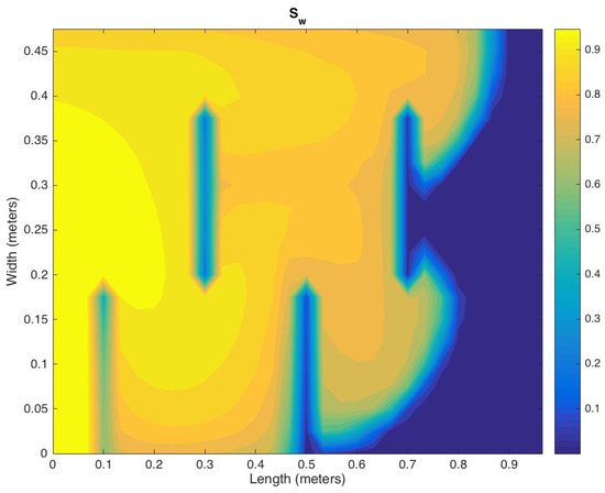
Figure 3.
Distribution of saturation on regular permeability map.
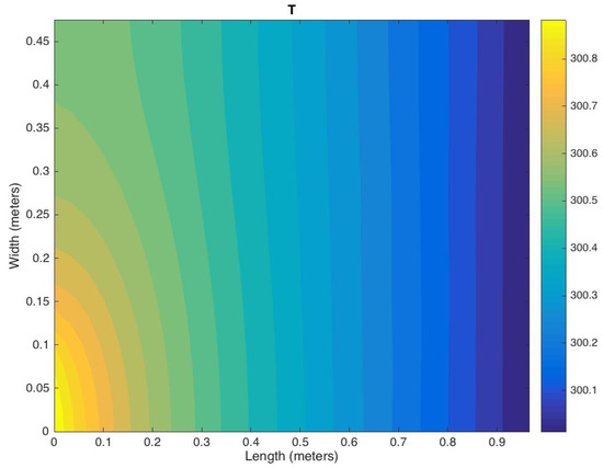
Figure 4.
Distribution of the temperature on regular permeability map after 0.75 PV.
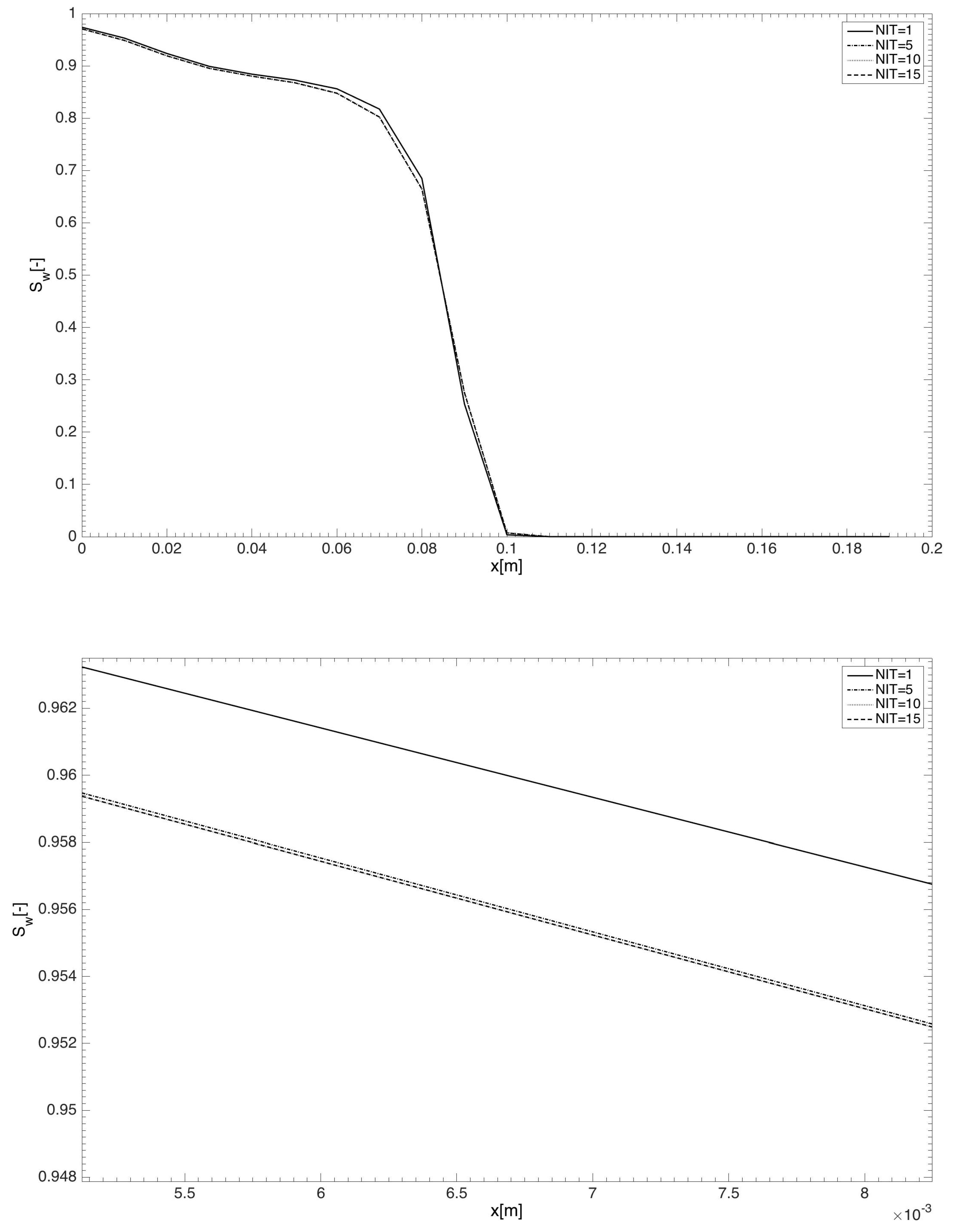
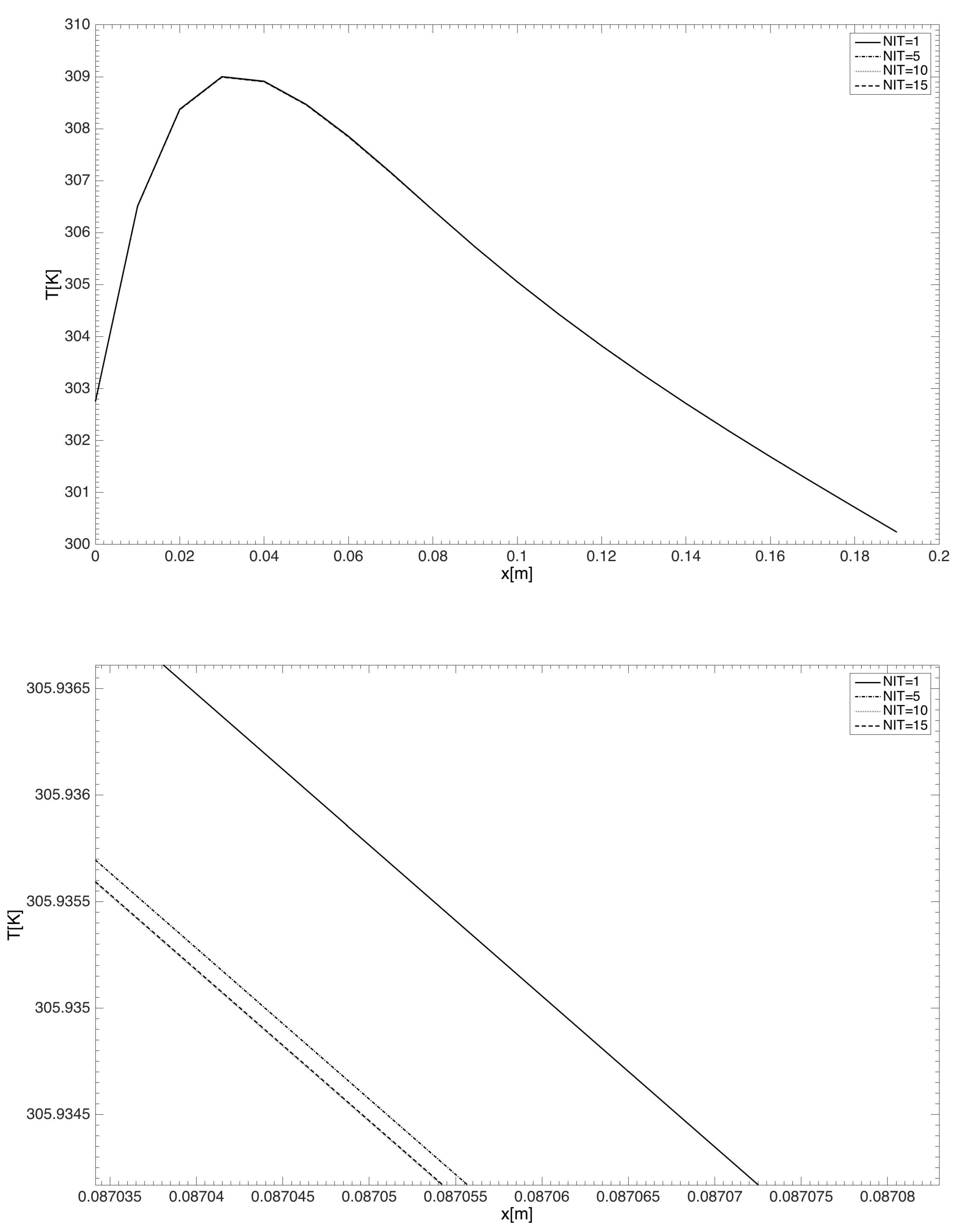
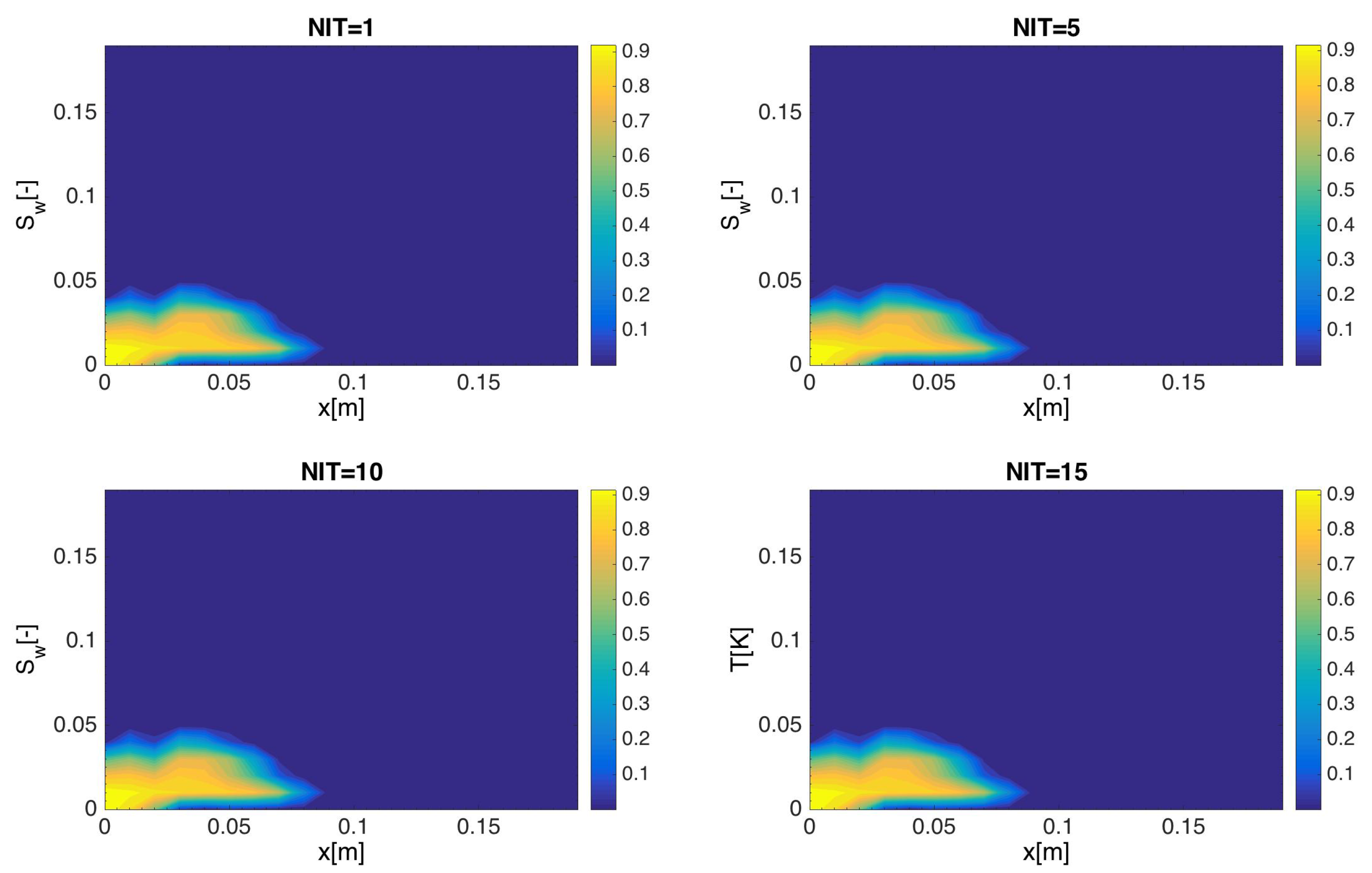
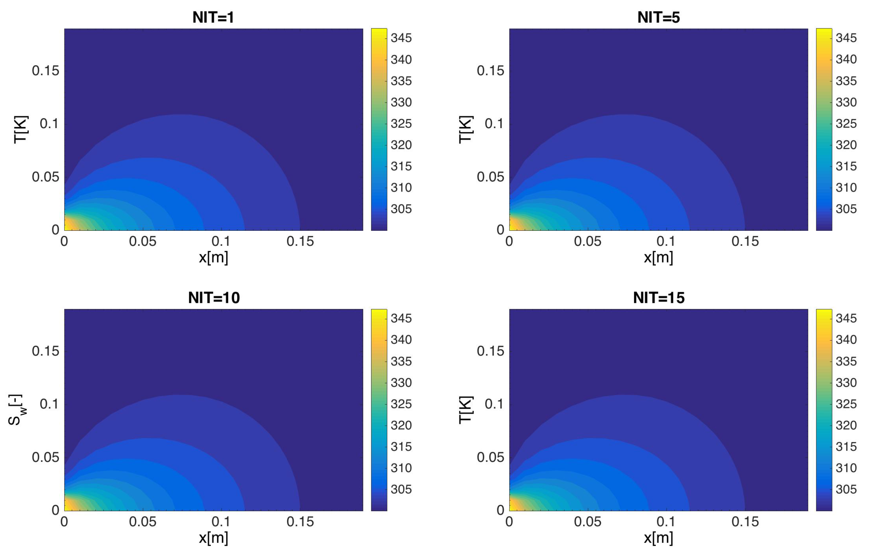
Finally, let us discuss some results to express the effectiveness of the proposed method (see Figure 5, Figure 6, Figure 7 and Figure 8). The domain of this test with a heterogeneous permeability is of size 0.2 × 0.2 m and a grid map of 20 × 20. The time step is 0.14. The results are plotted at NIT = 1 (non-iterative case) and NIT = 5, 10, 15 (iterative cases). In Figure 5, the saturation profiles at y = 0.01 m are plotted against the x-axis for different number of iterations (NIT). The lower graph is zoomed in. It can be seen from this figure, that there is a difference between the non-iterative case and the iterative cases. In addition, there are small differences between the iterative cases themselves which vanish as the NIT increases. A similar explanation can be presented for the temperature which is introduced in Figure 6, where the temperature profiles at y = 0.04 m are plotted against the x-axis for different number of iterations. The corresponding contours of saturation and temperature are presented, respectively, in Figure 7 and Figure 8.
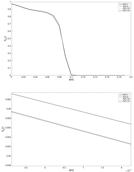
Figure 5.
Saturation profiles at y = 0.01 m against x-axis for different number of iterations (NIT). The lower graph is scaled up.
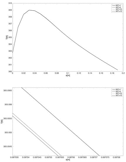
Figure 6.
Temperature profiles at y = 0.04 m against x-axis for different number of iterations. The lower graph is scaled up.
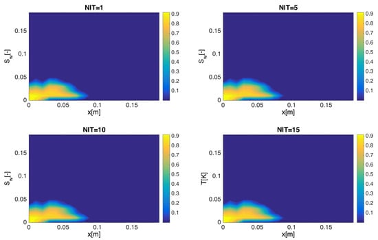
Figure 7.
Distribution of saturation on heterogeneous permeability for different number of iterations.
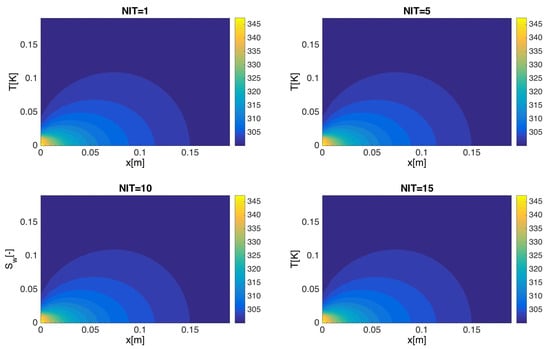
Figure 8.
Distribution of saturation on heterogeneous permeability for different number of iterations.
6. Conclusions
This paper dealt with the issue of non-isothermal two-phase flow in porous media. The model consists of an equation of flow that includes a term of body force represented by the approximation of Boussinesq and capillary forces, in addition to saturation and energy equations. We develop an iterative implicit pressure, explicit saturation, implicit temperature scheme to solve the system of the governing equations. In order to control the solution convergence, a relaxation factor is formulated as a function of the CFL stability condition. The pressure and saturation equations are coupled via a linearized capillary pressure. Then, the saturation equation is explicitly solved, while the energy equation is calculated implicitly. Both porosity and permeability are updated after each iteration loop. To demonstrate the performance of the current approach, some error estimates are presented for various values of number of time steps and number of iterations. Two numerical examples are provided. It was found that the medium heterogeneity has a clear effect on the saturation distribution while the opposite is true for the temperature distribution. Finally, the effectiveness of the proposed method has been discussed in terms of the number of iterations.
Funding
This research received no external funding.
Conflicts of Interest
The author declares no conflict of interest.
References
- Aziz, K.; Settari, A. Petroleum Reservoir Simulation; Applied Science Publishers: London, UK, 1979. [Google Scholar]
- Collins, D.A.; Nghiem, L.X.; Li, Y.K.; Grabenstetter, J.E. An efficient approach to adaptive implicit compositional simulation with an equation of state. SPE Res. Eng. 1992, 7, 259–264. [Google Scholar] [CrossRef]
- Dawson, C.N.; Kloe, H.; Wheeler, M.F.; Woodward, C.S. A parallel, implicit, cell-centered method for two-phase flow with a preconditioned Newton- Krylov solver. Comput. Geosci. 1997, 1, 215–249. [Google Scholar] [CrossRef]
- Ascher, U.; Ruuth, S.J.; Wetton, B.R. Implicit-Explicit methods for time-dependent partial differential equations. SIAM J. Numer. Anal. 1995, 32, 797–823. [Google Scholar] [CrossRef]
- Boscarino, S. Error analysis of IMEX Runge-Kutta methods derived from differential-algebraic systems. SIAM J. Numer. Anal. 2007, 45, 1600–1621. [Google Scholar] [CrossRef]
- Coats, K.H. IMPES stability: Selection of stable time steps. SPE J. 2003, 8, 181–187. [Google Scholar] [CrossRef]
- Jamei, M.; Ghafouri, H. A novel discontinuous Galerkin model for two-phase flow in porous media using an improved IMPES method. Int. J. Num. Meth. Heat Fluid Flow 2016, 26, 284–306. [Google Scholar] [CrossRef]
- Chen, Z.; Huan, G.; Ma, Y. Computational Methods for Multiphase Flows in Porous Media; SIAM Computational Science and Engineering: Philadelphia, PA, USA, 2006. [Google Scholar]
- Watts, J.W. A compositional formulation of the pressure and saturation equations. SPE Reserv. Eng. 1986, 1, 243–252. [Google Scholar] [CrossRef]
- Young, L.C.; Stephenson, R.E. A generalized compositional approach for reservoir simulation. SPE J. 1983, 23, 727–742. [Google Scholar] [CrossRef]
- Lacroix, S.; Vassilevski, Y.V.; Wheeler, J.A.; Wheeler, M.F. Iterative solution methods for modeling multiphase flow in porous media fully implicitly. SIAM J. Sci. Comput. 2003, 25, 905–926. [Google Scholar] [CrossRef]
- Lu, B.; Wheeler, M.F. Iterative coupling reservoir simulation on high performance computers. Pet. Sci. 2009, 6, 43–50. [Google Scholar] [CrossRef][Green Version]
- Kou, J.; Sun, S. A new treatment of capillarity to improve the stability of IMPES two-phase flow formulation. Comput. Fluids 2010, 39, 1923–1931. [Google Scholar] [CrossRef]
- El-Amin, M.F.; Kou, J.; Salama, A.; Sun, S. An iterative implicit scheme for nanoparticles transport with two-Phase flow in porous media. Procedia Comput. Sci. 2016, 80, 1344–1353. [Google Scholar] [CrossRef]
- El-Amin, M.F.; Kou, J.; Sun, S. Convergence analysis of the nonlinear iterative method for two-phase flow in porous media associated with nanoparticle injection. Int. J. Num. Meth. Heat Fluid Flow 2017, 27, 2289–2317. [Google Scholar] [CrossRef]
- Falta, R.W.; Pruess, K.; Javandel, I.; Witherspoon, P.A. Numerical Modelling of Steam Injection for the Removal of Nonaqueous Phase Liquids from the Subsurface. 2. Code Validation and Application. Adv. Water Res. 1992, 28, 451–465. [Google Scholar] [CrossRef]
- Forsyth, P.A. A positivity preserving method for simulation of steam injection for NAPL site remediation. Adv. Water Res. 1993, 16, 351–370. [Google Scholar] [CrossRef]
- Cortellessa, G.; Arpino, F.; Fraia, S.D.; Scungio, M. Two-phase explicit CBS procedure for compressible viscous flow transport in porous materials. Int. J. Num. Meth. Heat Fluid Flow 2018, 28, 336–360. [Google Scholar] [CrossRef]
- Nelson, P.H. Pore-throat sizes in sandstones, tight sandstones, and shales. AAPG Bull. 2009, 93, 329–340. [Google Scholar] [CrossRef]
- Bear, J. Dynamics of Fluids in Porous Media; American Elsevier: New York, NY, USA, 1972. [Google Scholar]
- Hassanizadeh, S.M.; Gray, W.G. Toward an improved description of the physics of two-phase flow. Adv. Water Resour. 1993, 16, 53–67. [Google Scholar] [CrossRef]
- Helmig, R. Multiphase Flow and Transport Processes in the Subsurface, 1st ed.; Series of Environmental Science and Engineering; Springer: Berlin/Heidelberg, Germany, 1997. [Google Scholar]
- Olivella, S.; Gens, A. Vapor transport in low permeability unsaturated soil with capillary effects. Trans. Porous Med. 2000, 40, 219–241. [Google Scholar] [CrossRef]
- Ortega, J.M.; Rheinboldt, W.C. Iterative Solution of Nonlinear Equations in Several Variables; SIAM: Philadelphia, PA, USA, 2000. [Google Scholar]
- Wheeler, M.F.; Yotov, I. A Multipoint Flux Mixed Finite Element Method. SIAM J. Numer. Anal. 2006, 44, 2082–2106. [Google Scholar] [CrossRef]
- Arbogast, T.; Wheeler, M.F.; Yotov, I. Mixed finite elements for elliptic problems with tensor coefficients as cell-centered finite differences. SIAM J. Numer. Anal. 1997, 34, 828–852. [Google Scholar] [CrossRef]
- Al-Dhafeeri, A.M.; Nasr-El-Din, H.A. Characteristics of high-permeability zones using core analysis, and production logging data. J. Pet. Sci. Eng. 2007, 55, 18–36. [Google Scholar] [CrossRef]
© 2019 by the author. Licensee MDPI, Basel, Switzerland. This article is an open access article distributed under the terms and conditions of the Creative Commons Attribution (CC BY) license (http://creativecommons.org/licenses/by/4.0/).

