
An Approach to Solid-State Electrical Double Layer Capacitors Fabricated with Graphene Oxide-Doped, Ionic Liquid-Based Solid Copolymer Electrolytes

Abstract
:1. Introduction
2. Methodology
2.1. Materials
2.2. Synthesis of Graphene Oxide
2.3. Preparation of Graphene Oxide Doped Solid Polymer Electrolyte
2.4. Fabrication of the Electrode
2.5. Characterization Techniques
2.6. Fabrication and the Electrochemical Measurements of EDLC
3. Results and Discussion
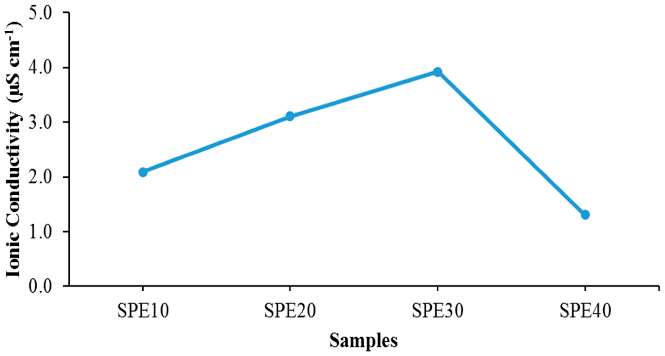
3.1. EIS Studies of Solid Polymer Electrolytes
3.2. Ion Conducting Mechanism
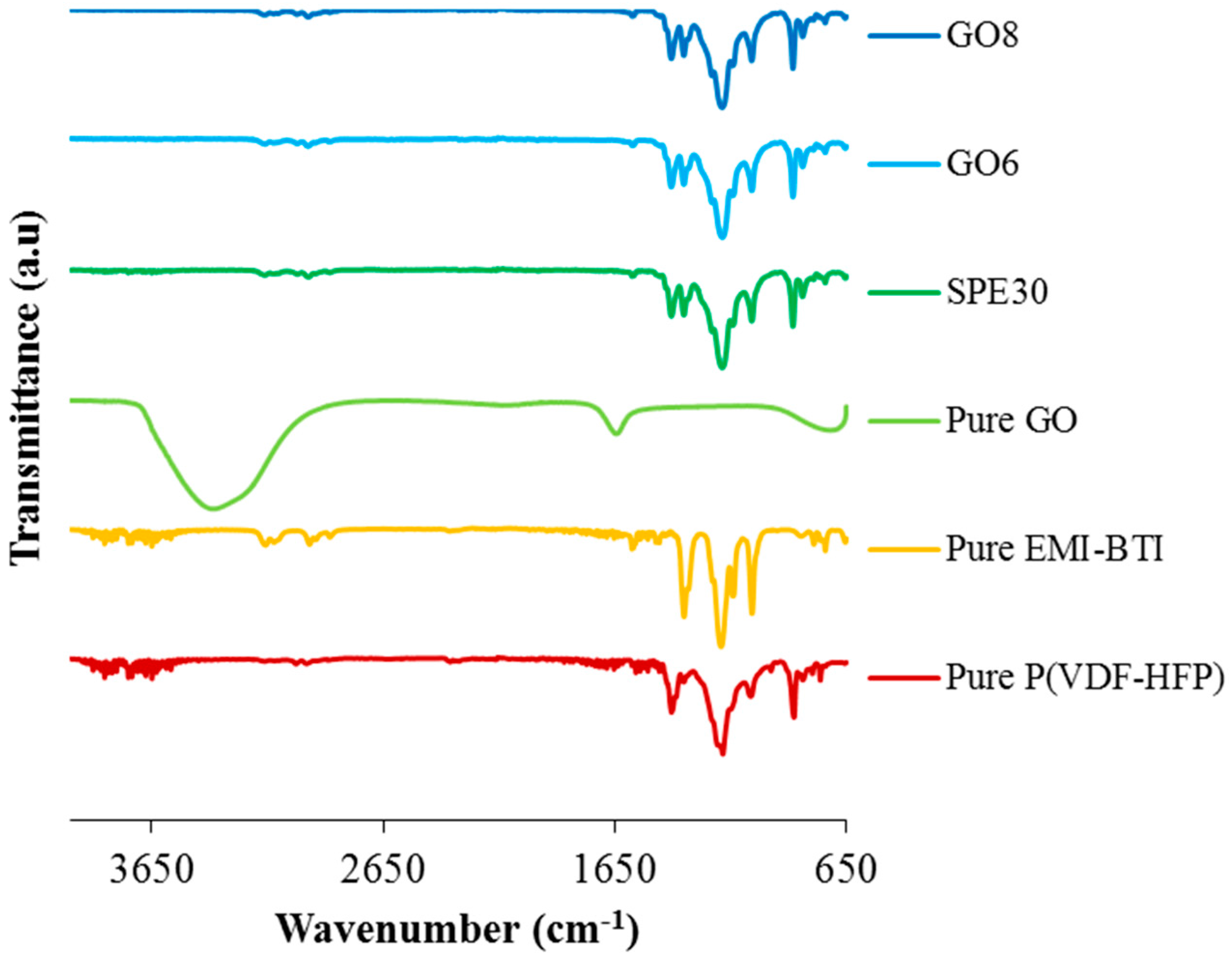
3.3. FTIR Measurements of Solid Polymer Electrolytes
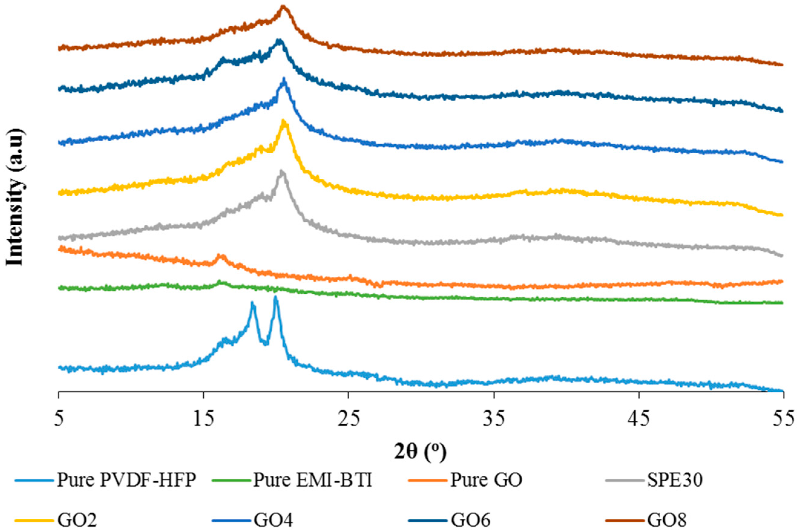
3.4. X-ray Diffraction Studies
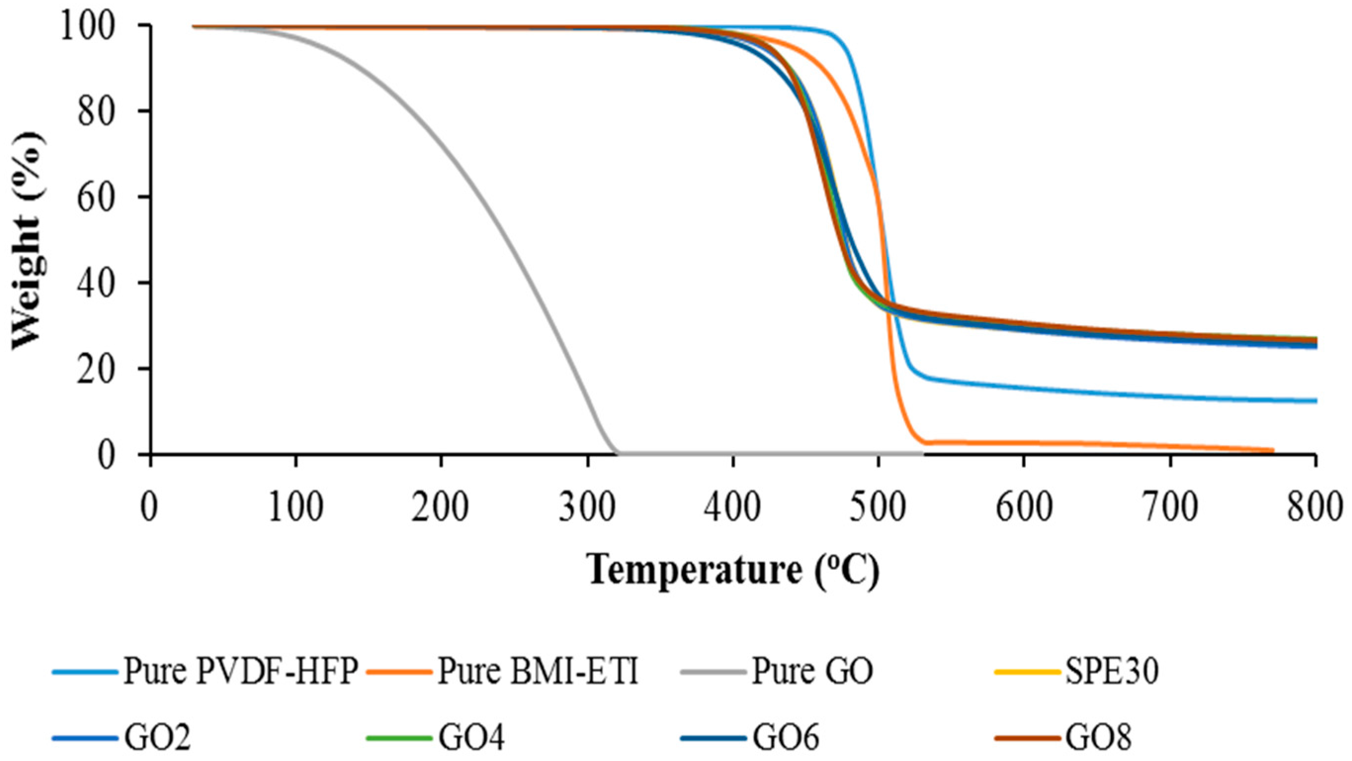
3.5. Thermogravimetric Analysis (TGA)
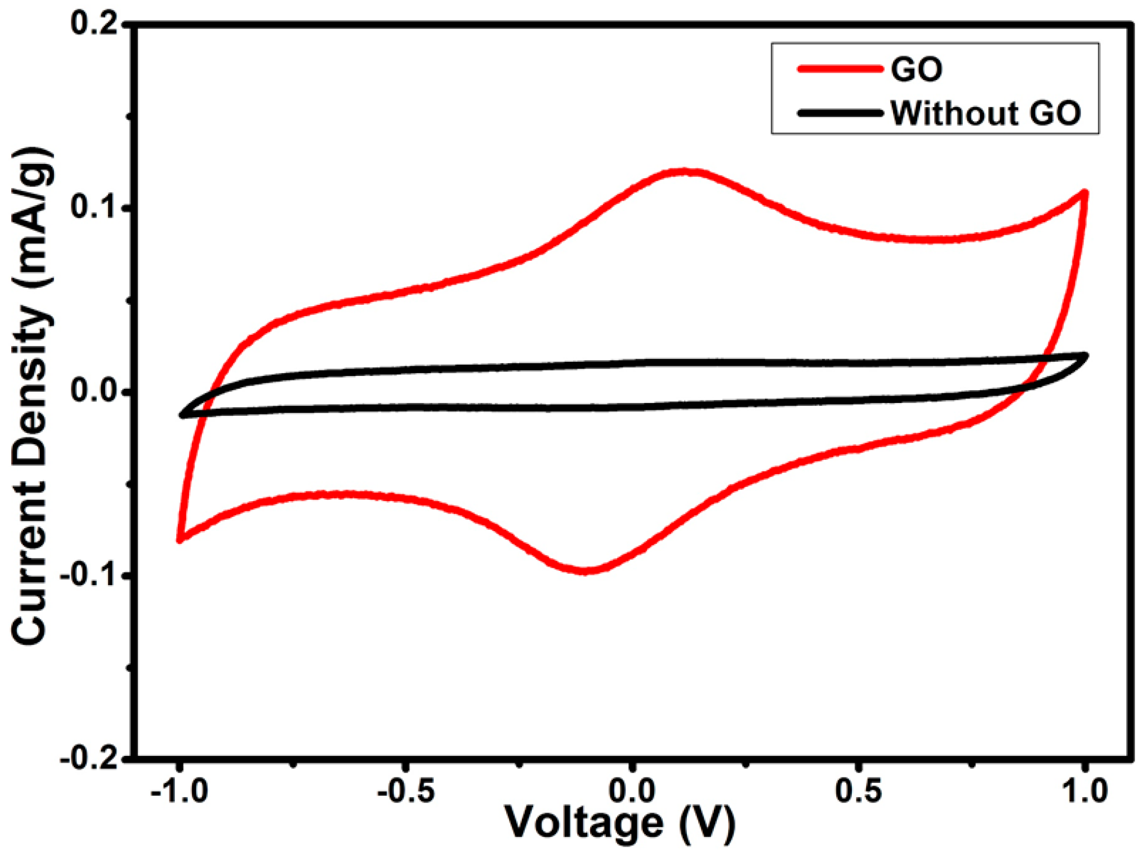
3.6. Electrochemical Impedance (EIS) Performance of the EDLC
4. Conclusions
Acknowledgments
Author Contributions
Conflicts of Interest
References
- Sudhakar, Y.N.; Selvakumar, M.; Bhat, D.K. Tubular array, dielectric, conductivity and electrochemical properties of biodegradable gel polymer electrolyte. Mater. Sci. Eng. B 2014, 180, 12–19. [Google Scholar] [CrossRef]
- Yang, X.; Zhang, F.; Zhang, L.; Zhang, T.; Huang, Y.; Chen, Y. A high-performance graphene oxide-doped ion gel as gel polymer electrolyte for all-solid-state supercapacitor applications. Adv. Funct. Mater. 2013, 23, 3353–3360. [Google Scholar] [CrossRef]
- Manuel Stephan, A.; Nahm, K.S. Review on composite polymer electrolytes for lithium batteries. Polymer 2016, 47, 5952–5964. [Google Scholar] [CrossRef]
- Abbrent, S.; Plestil, J.; Hlavata, D.; Lindgren, J.; Tegenfeldt, J.; Wendsjö, Å. Crystallinity and morphology of PVdF–HFP-based gel electrolytes. Polymer 2001, 42, 1407–1416. [Google Scholar] [CrossRef]
- Stolarska, M.; Niedzicki, L.; Borkowska, R.; Zalewska, A.; Wieczorek, W. Structure, transport properties and interfacial stability of PVdF/HFP electrolytes containing modified inorganic filler. Electrochim. Acta 2007, 53, 1512–1517. [Google Scholar] [CrossRef]
- Manuel Stephan, A.; Nahm, K.S.; Anbu Kulandainathan, M.; Ravi, G.; Wilson, J. Electrochemical studies on nanofiller incorporated poly(vinylidene fluoride-hexafluoropropylene) (PVdF-HFP) composite electrolytes for lithium batteries. J. Appl. Electrochem. 2006, 36, 1091–1097. [Google Scholar] [CrossRef]
- Lu, J.; Yan, F.; Texter, J. Advanced applications of ionic liquids in polymer science. Prog. Polym. Sci. 2009, 34, 431–448. [Google Scholar] [CrossRef]
- Joshi, R.; Pasilis, S.P. The effect of tributylphosphate and tributyl phosphine oxide on hydrogen bonding interactions between water and the 1-ethyl-3-methylimidazolium cation in 1-ethyl-3-methylimidazolium bis(trifluoromethylsulfonyl)imide. J. Mol. Liq. 2015, 209, 381–386. [Google Scholar] [CrossRef]
- Ravi, M.; Kiran Kumar, K.; Madhu Mohan, V.; Narasimha Rao, V.V.R. Effect of nano TiO2 filler on the structural and electrical properties of PVP based polymer electrolyte films. Polym. Test. 2014, 33, 152–160. [Google Scholar] [CrossRef]
- Choi, Y.R.; Yoon, Y.-G.; Choi, K.S.; Kang, J.H.; Shim, Y.-S.; Kim, Y.H.; Chang, H.J.; Lee, J.-H.; Park, C.R.; Kim, S.Y. Role of oxygen functional groups in graphene oxide for reversible room-temperature NO2 sensing. Carbon 2016, 91, 178–187. [Google Scholar] [CrossRef]
- Jayalakshmi, M.; Balasubramanian, K. Simple capacitors to supercapacitors-An overview. Int. J. Electrochem. Sci. 2008, 3, 1196–1217. [Google Scholar]
- Numan, A.; Duraisamy, N.; Saiha Omar, F.; Mahipal, Y.K.; Ramesh, K.; Ramesh, S. Enhanced electrochemical performance of cobalt oxide nanocube intercalated reduced graphene oxide for supercapacitor application. RSC Adv. 2016, 6, 34894–34902. [Google Scholar] [CrossRef]
- Liu, H.; Zhang, L.; Guo, Y.; Cheng, C.; Yang, L.; Jiang, L.; Yu, G.; Hu, W.; Liu, Y.; Zhu, D. Reduction of graphene oxide to highly conductive graphene by Lawesson’s reagent and its electrical applications. J. Mater. Chem. C 2013, 1, 3104. [Google Scholar] [CrossRef]
- Rajendran, R.; Shrestha, L.K.; Minami, K.; Subramanian, M.; Jayavel, R.; Ariga, K. Dimensionally integrated nanoarchitectonics for a novel composite from 0D, 1D, and 2D nanomaterials: RGO/CNT/CeO 2 ternary nanocomposites with electrochemical performance. J. Mater. Chem. A 2014, 2, 18480–18487. [Google Scholar] [CrossRef]
- Rajendran, R.; Shrestha, L.K.; Kumar, R.M.; Jayavel, R.; Hill, J.P.; Ariga, K. Composite nanoarchitectonics for ternary systems of reduced graphene oxide/carbon nanotubes/nickel oxide with enhanced electrochemical capacitor performance. J. Inorg. Organomet. Polym. Mater. 2015, 25, 267–274. [Google Scholar] [CrossRef]
- Merlet, C.; Rotenberg, B.; Madden, P.A.; Taberna, P.-L.; Simon, P.; Gogotsi, Y.; Salanne, M. On the molecular origin of supercapacitance in nanoporous carbon electrodes. Nat. Mater. 2012, 11, 306–310. [Google Scholar] [CrossRef] [PubMed]
- Liew, C.W.; Ramesh, S.; Arof, A.K. Characterization of ionic liquid added poly(vinyl alcohol)-based proton conducting polymer electrolytes and electrochemical studies on the supercapacitors. Int. J. Hydrog. Energy 2015, 40, 852–862. [Google Scholar] [CrossRef]
- Peik-See, T.; Pandikumar, A.; Ngee, L.H.; Ming, H.N.; Hua, C.C. Magnetically separable reduced graphene oxide/iron oxide nanocomposite materials for environmental remediation. Catal. Sci. Technol. 2014, 4, 4396–4405. [Google Scholar] [CrossRef]
- Nadiah, N.S.; Mahipal, Y.K.; Numan, A.; Ramesh, S.; Ramesh, K. Efficiency of supercapacitor using EC/DMC-based liquid electrolytes with methyl methacrylate (MMA) monomer. Ionics 2015, 22, 1–8. [Google Scholar] [CrossRef]
- Qian, X.; Gu, N.; Cheng, Z.; Yang, X.; Wang, E.; Dong, S. Methods to study the ionic conductivity of polymeric electrolytes using A.C. impedance spectroscopy. J. Solid State Electrochem. 2001, 6, 8–15. [Google Scholar] [CrossRef]
- Zhang, R.; Chen, Y.; Montazami, R. Ionic liquid-doped gel polymer electrolyte for flexible lithium-ion polymer batteries. Materials 2015, 8, 2735–2748. [Google Scholar] [CrossRef]
- Shamsuri, A.A.; Daik, R. Applications of ionic liquids and their mixtures for preparation of advanced polymer blends and composites: A short review. Rev. Adv. Mater. Sci. 2014, 40, 45–59. [Google Scholar]
- Ramesh, S.; Liew, C.W.; Arof, A.K. Ion conducting corn starch biopolymer electrolytes doped with ionic liquid 1-butyl-3-methylimidazolium hexafluorophosphate. J. Non-Cryst. Solids 2011, 357, 3654–3660. [Google Scholar] [CrossRef]
- Ye, Y.S.; Wang, H.; Bi, S.G.; Xue, Y.; Xue, Z.G.; Liao, Y.G.; Zhou, X.P.; Xie, X.L.; Mai, Y.W. Enhanced ion transport in polymer–ionic liquid electrolytes containing ionic liquid-functionalized nanostructured carbon materials. Carbon 2015, 86, 86–97. [Google Scholar] [CrossRef]
- Dreyer, D.R.; Park, S.; Bielawski, C.W.; Ruoff, R.S. The chemistry of graphene oxide. Chem. Soc. Rev. 2010, 39, 228–240. [Google Scholar] [CrossRef] [PubMed]
- Shim, J.; Kim, D.-G.; Kim, H.J.; Lee, J.H.; Baik, J.-H.; Lee, J.-C. Novel composite polymer electrolytes containing poly(ethylene glycol)-grafted graphene oxide for all-solid-state lithium-ion battery applications. J. Mater. Chem. A 2014, 2, 13873. [Google Scholar] [CrossRef]
- Ye, Y.-S.; Rick, J.; Hwang, B.-J. Ionic liquid polymer electrolytes. J. Mater. Chem. A 2013, 1, 2719–2743. [Google Scholar] [CrossRef]
- Khan, M.S.; Shakoor, A. Ionic conductance, thermal and morphological behaviour of peo-graphene oxide-salts composites. J. Chem. 2015. [Google Scholar] [CrossRef]
- Ahmad, S.; Deepa, M.; Agnihotry, S.A. Effect of salts on the fumed silica-based composite polymer electrolytes. Sol. Energy Mater. Sol. Cells 2008, 92, 184–189. [Google Scholar] [CrossRef]
- Sivakumar, M.; Subadevi, R.; Rajendran, S.; Wu, H.-C.; Wu, N.-L. Compositional effect of PVdF–PEMA blend gel polymer electrolytes for lithium polymer batteries. Eur. Polym. J. 2007, 43, 4466–4473. [Google Scholar] [CrossRef]
- Ramesh, S.; Lu, S.-C.; Vankelecom, I. BMIMTf ionic liquid-assisted ionic dissociation of MgTf in P(VdF-HFP)-based solid polymer electrolytes. J. Phys. Chem. Solids 2013, 74, 1380–1386. [Google Scholar] [CrossRef]
- Sa’adun, N.N.; Subramaniam, R.; Kasi, R. Development and characterization of poly(1-vinylpyrrolidone-co-vinyl acetate) copolymer based polymer electrolytes. Sci. World J. 2014, 2014, 1–7. [Google Scholar] [CrossRef] [PubMed]
- Cao, Y.C.; Xu, C.; Wu, X.; Wang, X.; Xing, L.; Scott, K. A poly (ethylene oxide)/graphene oxide electrolyte membrane for low temperature polymer fuel cells. J. Power Sources 2011, 196, 8377–8382. [Google Scholar] [CrossRef]
- Noor, M.M.; Buraidah, M.H.; Careem, M.A.; Majid, S.R.; Arof, A.K. An optimized poly(vinylidene fluoride-hexafluoropropylene)-NaI gel polymer electrolyte and its application in natural dye sensitized solar cells. Electrochim. Acta 2014, 121, 159–167. [Google Scholar] [CrossRef]
- Noor, M.M.; Careem, M.A.; Majid, S.R.; Arof, A.K. Characterisation of plasticised PVDF–HFP polymer electrolytes. Mater. Res. Innov. 2011, 15, 157–160. [Google Scholar] [CrossRef]
- Yang, X.; Zhang, L.; Zhang, F.; Zhang, T.; Huang, Y.; Chen, Y. A high-performance all-solid-state supercapacitor with graphene-doped carbon material electrodes and a graphene oxide-doped ion gel electrolyte. Carbon 2014, 72, 381–386. [Google Scholar] [CrossRef]
- Pandey, G.P.; Hashmi, S.A. Ionic liquid 1-ethyl-3-methylimidazolium tetracyanoborate-based gel polymer electrolyte for electrochemical capacitors. J. Mater. Chem. A 2013, 1, 3372–3378. [Google Scholar] [CrossRef]
- Pandey, G.P.; Hashmi, S.A. Solid-state supercapacitors with ionic liquid based gel polymer electrolyte: Effect of lithium salt addition. J. Power Sources 2013, 243, 211–218. [Google Scholar] [CrossRef]
- Lim, C.-S.; Teoh, K.H.; Liew, C.-W.; Ramesh, S. Capacitive behaviour studies on electrical double layer capacitor using poly (vinyl alcohol)-lithium perchlorate based polymer electrolyte incorporated with TiO2. Mater. Chem. Phys. 2014, 143, 661–667. [Google Scholar] [CrossRef]
- Teoh, K.H.; Lim, C.-S.; Liew, C.-W.; Ramesh, S.; Ramesh, S. Electric double-layer capacitors with corn starch-based biopolymer electrolytes incorporating silica as filler. Ionics 2015, 21, 2061–2068. [Google Scholar] [CrossRef]
- Lu, J.; Zhang, Y.; Lu, Z.; Huang, X.; Wang, Z.; Zhu, X.; Wei, B. A preliminary study of the pseudo-capacitance features of strontium doped lanthanum manganite. RSC Adv. 2015, 8, 5858–5862. [Google Scholar] [CrossRef]
- Yu, H.; Wu, J.; Fan, L.; Lin, Y.; Xu, K.; Tang, Z.; Cheng, C.; Tang, S.; Lin, J.; Huang, M.; et al. A novel redox-mediated gel polymer electrolyte for high-performance supercapacitor. J. Power Sources 2012, 198, 402–407. [Google Scholar] [CrossRef]
- Roldn, S.; Blanco, C.; Granda, M.; Menndez, R.; Santamar, R. Towards a further generation of high-energy carbon-based capacitors by using redox-active electrolytes. Angew. Chem. Int. Ed. 2011, 50, 1699–1701. [Google Scholar] [CrossRef] [PubMed]


| Electrolytes | Composition PVdF-HFP:EMI-BTI:GO | PVdF-HFP (g) | EMI-BTI (g) | GO (g) |
|---|---|---|---|---|
| SPE10 | 90:10:0 | 0.900 | 0.100 | - |
| SPE20 | 80:20:0 | 0.800 | 0.200 | - |
| SPE30 | 70:30:0 | 0.700 | 0.300 | - |
| SPE40 | 60:40:0 | 0.600 | 0.400 | - |
| GO2 | 68.6:29.4:2 | 0.686 | 0.294 | 0.02 |
| GO4 | 67.2:28.8:4 | 0.672 | 0.288 | 0.04 |
| GO6 | 65.8:28.2:6 | 0.658 | 0.282 | 0.06 |
| GO8 | 64.4:27.6:8 | 0.644 | 0.276 | 0.08 |
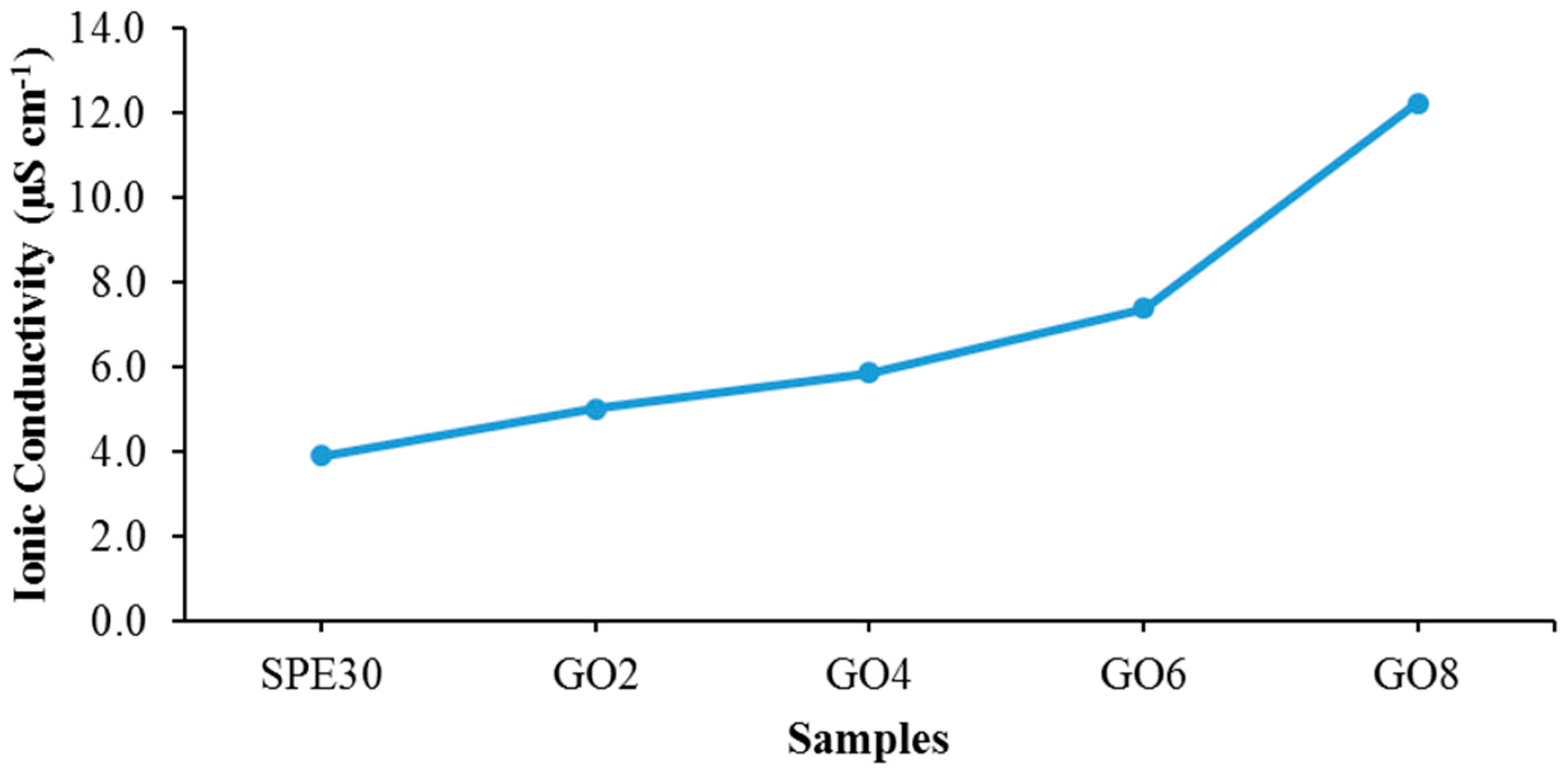
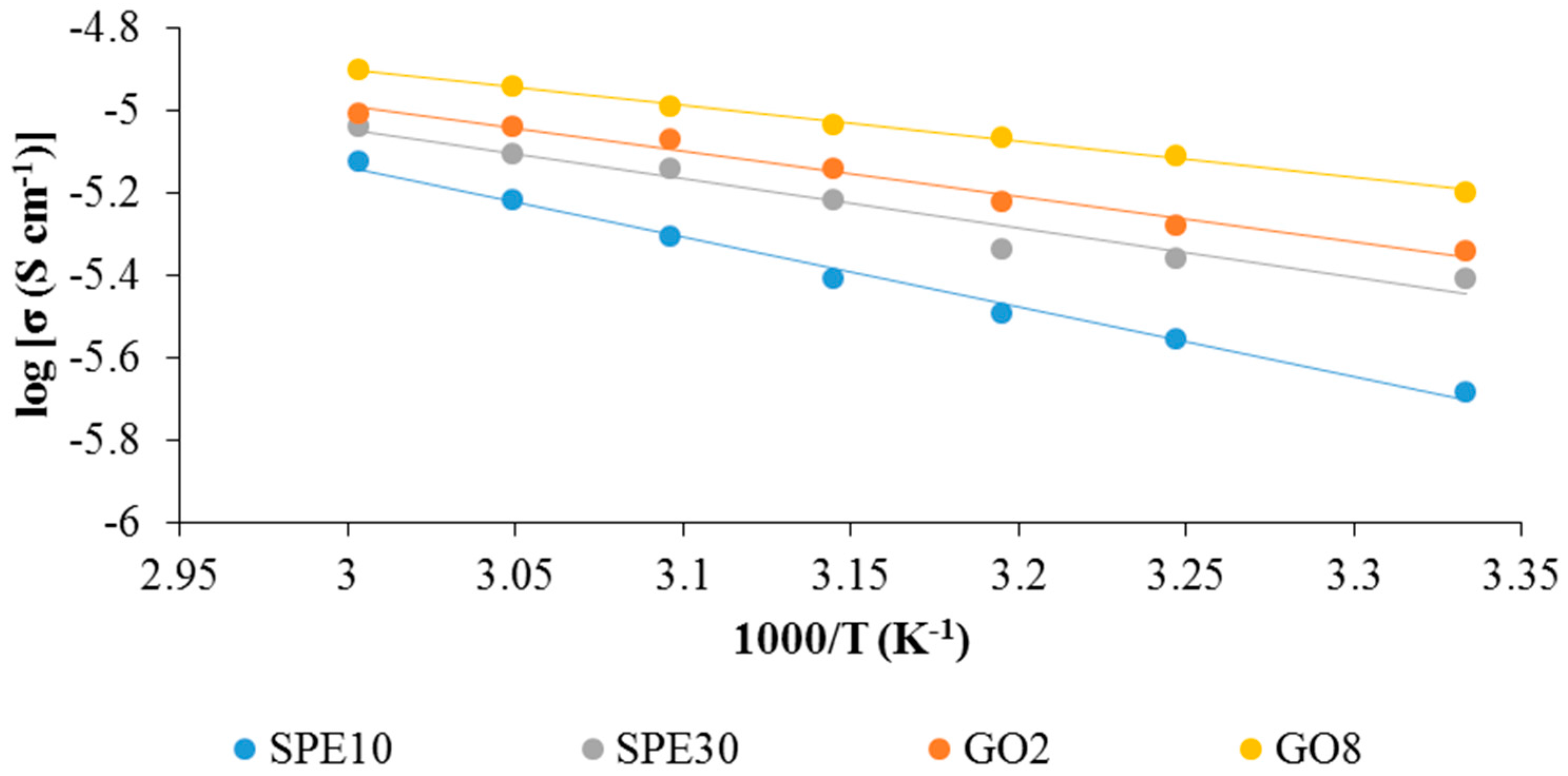
| Electrolytes | Ionic Conductivity (µS cm−1) | Activation Energy, Ea (eV) |
|---|---|---|
| SPE10 | 2.09 | 0.147 |
| SPE20 | 3.11 | 0.120 |
| SPE30 | 3.92 | 0.104 |
| SPE40 | 1.31 | 0.171 |
| GO2 | 5.03 | 0.095 |
| GO4 | 5.88 | 0.089 |
| GO6 | 7.40 | 0.079 |
| GO8 | 12.25 | 0.076 |
| Samples | Wavenumber (cm−1) | Possible Assignments |
|---|---|---|
| Pure PVdF-HFP | 762, 854 | α-phase |
| 796 | CF3 stretching | |
| 838, 875 | Amorphous region | |
| 1062 | C-C skeletal vibration | |
| 1182 | Symmetrical stretching of -CF3 | |
| 1202 | Asymmetrical stretching of -CF2- | |
| 1404 | -C-F-strectching | |
| Pure EMI-BTI | 854 | In-plane bending of imidazole ring |
| 949 | In-plane bending of CNC | |
| 1352 | Symmetrical bending in-plane of CH | |
| 1386 | In-plane asymmetrical stretching of imidazole ring | |
| 1457 | Symmetrical in-play bending of imidazole ring | |
| 1576 | HCN deformation | |
| 2980 | CH stretching in methyl group | |
| 3120, 3157 | =C-H stretching | |
| 3587 | CH stretching |
| Samples | Decomposition Temperature, TD (°C) |
|---|---|
| Pure PVdF-HFP | 501.28 |
| Pure EMI-BTI | 500.15 |
| Pure GO | 194.08 |
| SPE30 | 448.96 |
| GO2 | 448.78 |
| GO4 | 444.53 |
| GO6 | 438.95 |
| GO8 | 437.84 |
© 2016 by the authors; licensee MDPI, Basel, Switzerland. This article is an open access article distributed under the terms and conditions of the Creative Commons Attribution (CC-BY) license (http://creativecommons.org/licenses/by/4.0/).
Share and Cite
Fattah, N.F.A.; Ng, H.M.; Mahipal, Y.K.; Numan, A.; Ramesh, S.; Ramesh, K. An Approach to Solid-State Electrical Double Layer Capacitors Fabricated with Graphene Oxide-Doped, Ionic Liquid-Based Solid Copolymer Electrolytes. Materials 2016, 9, 450. https://doi.org/10.3390/ma9060450
Fattah NFA, Ng HM, Mahipal YK, Numan A, Ramesh S, Ramesh K. An Approach to Solid-State Electrical Double Layer Capacitors Fabricated with Graphene Oxide-Doped, Ionic Liquid-Based Solid Copolymer Electrolytes. Materials. 2016; 9(6):450. https://doi.org/10.3390/ma9060450
Chicago/Turabian StyleFattah, N. F. A., H. M. Ng, Y. K. Mahipal, Arshid Numan, S. Ramesh, and K. Ramesh. 2016. "An Approach to Solid-State Electrical Double Layer Capacitors Fabricated with Graphene Oxide-Doped, Ionic Liquid-Based Solid Copolymer Electrolytes" Materials 9, no. 6: 450. https://doi.org/10.3390/ma9060450
APA StyleFattah, N. F. A., Ng, H. M., Mahipal, Y. K., Numan, A., Ramesh, S., & Ramesh, K. (2016). An Approach to Solid-State Electrical Double Layer Capacitors Fabricated with Graphene Oxide-Doped, Ionic Liquid-Based Solid Copolymer Electrolytes. Materials, 9(6), 450. https://doi.org/10.3390/ma9060450