Article

Assembly of CdS Quantum Dots onto Hierarchical TiO2 Structure for Quantum Dots Sensitized Solar Cell Applications

1
Department of Physics and Astronomy, College of Sciences, P.O. Box 2455, King Saud University, Riyadh 11451, Saudi Arabia
2
National Institute of Laser and Optronics, Nilore, Islamabad 45650, Pakistan
*
Authors to whom correspondence should be addressed.
Materials 2015, 8(5), 2376-2386; https://doi.org/10.3390/ma8052376
Submission received: 27 January 2015 / Revised: 13 April 2015 / Accepted: 27 April 2015 / Published: 5 May 2015
(This article belongs to the Section Energy Materials)

Abstract

:
Quantum dot (QD) sensitized solar cells based on Hierarchical TiO2 structure (HTS) consisting of spherical nano-urchins on transparent conductive fluorine doped tin oxide glass substrate is fabricated. The hierarchical TiO2 structure consisting of spherical nano-urchins on transparent conductive fluorine doped tin oxide glass substrate synthesized by hydrothermal route. The CdS quantum dots were grown by the successive ionic layer adsorption and reaction deposition method. The quantum dot sensitized solar cell based on the hierarchical TiO2 structure shows a current density JSC = 1.44 mA, VOC = 0.46 V, FF = 0.42 and η = 0.27%. The QD provide a high surface area and nano-urchins offer a highway for fast charge collection and multiple scattering centers within the photoelectrode.

1. Introduction

In the modern age, solar cells have attracted significant attention due to their promising applications in energy generation devices. Since the pioneering report by O’Regan and Grätzel in 1991, dye-sensitized solar cells have been investigated extensively all over the world [1,2,3,4,5,6,7,8,9,10,11]. The quantum dot sensitized solar cell (QDSSC) has received wide attentions recently because they have several advantages over dye sensitizers, such as tunable energy gaps [12], high absorption coefficients [13], and generation of multiple electron-hole pair with high energy excitation [14].
The TiO2 nanoparticle based photoelectrode showed considerable power conversion efficiency over a large surface area with the attachment of dye molecules. M. Pavan et al. reported on an oxide heterojunction solar cell, entirely produced by spray pyrolysis onto fluorine doped tin oxide (FTO) covered glass substrates [15]. However, the irregular stacking of TiO2 nanocrystallines have been found to limit the electron transportation and decreases the electron life time because of the random network of crystallographically misaligned crystallites, and lattice mismatches at the grain boundaries [15,16,17,18]. It has been accepted that the value of power conversion efficiency of photoelectrodes highly depends on the morphology and structure of TiO2. In order to increase the photovoltaic performance, through their excellent electron transport and light scattering ability, one-dimensional nanostructures, such as nanorods (NRs), nanowires (NWs) or nanotubes (NTs), have been studied as photoelectrode materials for sensitized solar cells [19,20,21,22,23]. Due to low specific surface area ascribing to larger diameter and wide gaps among neighbor NWs [23,24], the TiO2 NWs based photoelectrode has not shown remarkable enhancement of power conversion efficiency. To overcome this problem, hierarchically-structured materials composed of nanocrystallites that form large micro-spheres. Nanocrystallites can provide excellent light scattering with large surface area for sensitizer-uptake. In these hierarchical materials, slow trap-limited charge transport remains a fundamental problem. To solve this problem, a nanourchin (NU) TiO2 are formed by clustering nanowires that have a mean diameter of about 50 nm and a length of a few micrometers to construct a radially aligned structure. There are few recent examples concerning hierarchical TiO2 structure (HTS), such as either for rutile TiO2 on FTO glass or anatase TiO2 on a Ti foil substrate for improving the power conversion efficiency [19,24].
In the present work, hierarchical TiO2 structure (HTS) consisting of spherical nano-urchins was synthesized through hydrothermal method. The CdS QDs were assembled by successive ion layer adsorption and reaction (SILAR). The HTS/CdS QDs based photoelectrode was used to improve the power conversion efficiency of quantum dot sensitized solar cell.

2. Experimental

2.1. Synthesis of Hierarchical TiO2 Structure

The hierarchical TiO2 structure (HTS) was grown on the FTO substrate. In a typical synthesis, the substrate was ultrasonically cleaned sequentially in acetone, isopropyl alcohol and deionized water for 15 min and was finally dried with nitrogen flow. Separately, 1 mL of titanium isopropoxide was added dropwise to a 1:1 mixture of deionized water and concentrated (35%) hydrochloric acid to obtain a clear transparent solution. The substrate was placed at an angle in a 100 mL Teflon liner, and the precursor solution was added to it. The Teflon liner was loaded in an autoclave and was placed in furnace. The growth was carried out at 180 °C for 15 h.

2.2. Deposition of CdS Quantum Dots (QD)

The CdS quantum dots were deposited on HTS films by successive ionic layer deposition and reaction (SILAR) method. The HTS electrode was exposed to Cd2+ and S2− ion successive immersion in a ethanolic solutions of 0.5 M Cd(NO3)2 and methnolic solution of 0.5 M Na2S. The film was dipped into 0.5 M Cd(NO3)2 solution for 1 min and rinsed with ethanol and then, dipped into 0.5 M Na2S for 1 min and rinsed with methanol. These dipping procedures are considered one cycle. The coating procedure was repeated 10 times. For the deposition of CdS on the HTS by SILAR method, the experimental procedure is explained as follow:
( HTS ) Cd 2+    ( HTS ) C d 2 +     Rinsed S 2    ( HTS ) Cds     Rinsed

2.3. Preparation of Electrolyte Solution

Polysulfide electrolytes were prepared by mixing suitable quantities of Na2S, S, and KCl powders in water/methanol solution taken in the ratio 3/7.

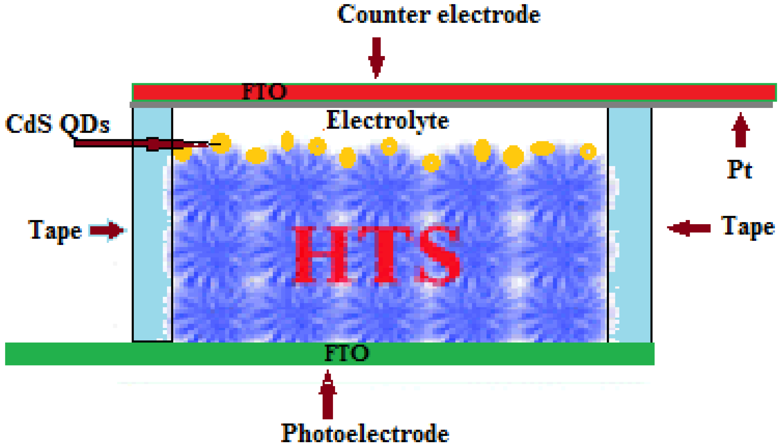
2.4. Fabrication of QDSCs

The QD-adsorbed HTS was used as the working electrode and platinum coated FTO glass as counter electrode. The electrodes were assembled into a sealed cell with a cello tape spacer and binder clips, with an active area equal to 0.36 cm2. The electrolyte was injected from the edges into the open cell, and the cell was tested. The schematic of the studied QDSSCs is shown in Figure 1.
Figure 1. Schematic of the Hierarchical TiO2 structure (HTS) based quantum dot sensitized solar cell (QDSSC).
Materials 08 02376 g001

2.5. Characterization

X-Ray diffraction XRD analysis of HTS/FTO films was carried out using multipurpose X-ray diffractometer (Bruker D8 Discover, Bruker AXS GmbH, Karlsruhe, Germany) with Cukα source radiation. Surface morphology of the films was investigated with a JEOL (JSM-7600F) Field Emission electron microscope (Jeol, Peabody, MA, USA). Size of the CdS QDs was measured by JEOL (JEM-2100F) field emission electron microscope (FETEM) (Jeol, Peabody, MA, USA). Optical absorption studies were made at room temperature by using UV-Vis-NIR spectrophotometer (JASCO-V 670) (Jasco, Halifax, NS, Canada) in the wavelength range 200 nm–800 nm. The current-voltage and capacitance-voltage characteristics were investigated using a Semiconductor Characterization System SC-4200 from Keithley (Keithley Instruments, Solon, OH, USA). The films were illuminated by a Class-BBA Solar Simulator (PV measurements, Boulder, CO, USA) and TM-206 solar power meter (Tenmars, Taipei, Taiwan) was used for measuring the light intensity.

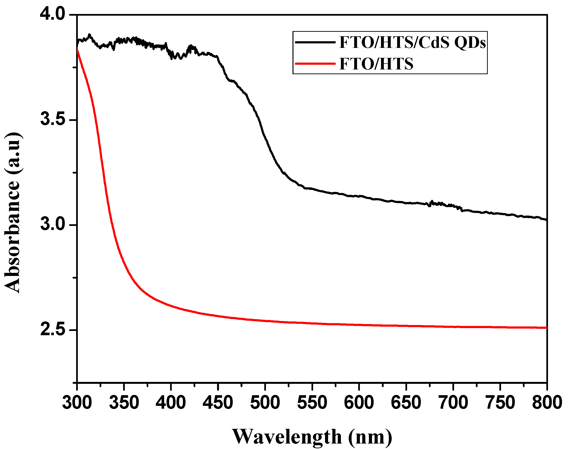
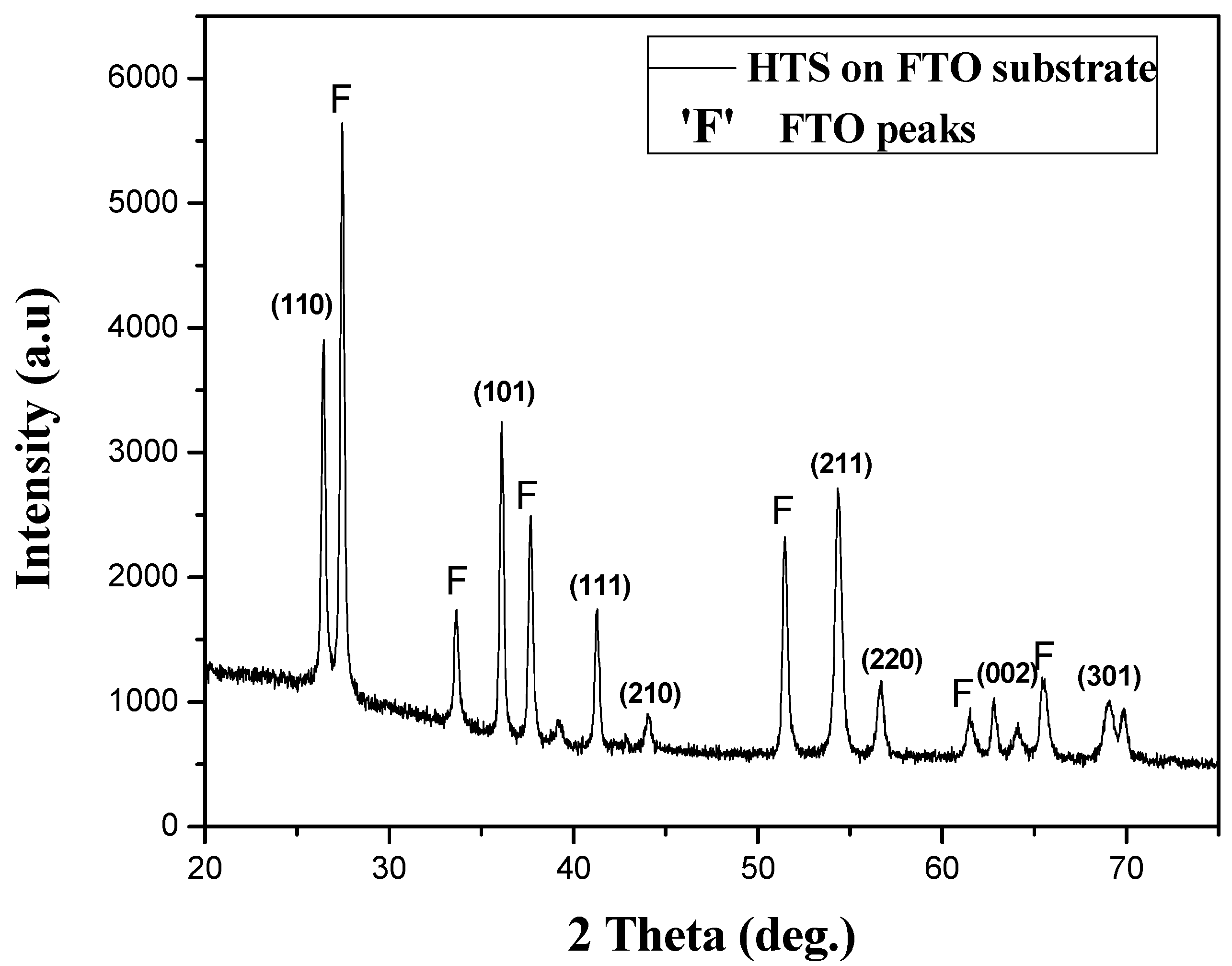
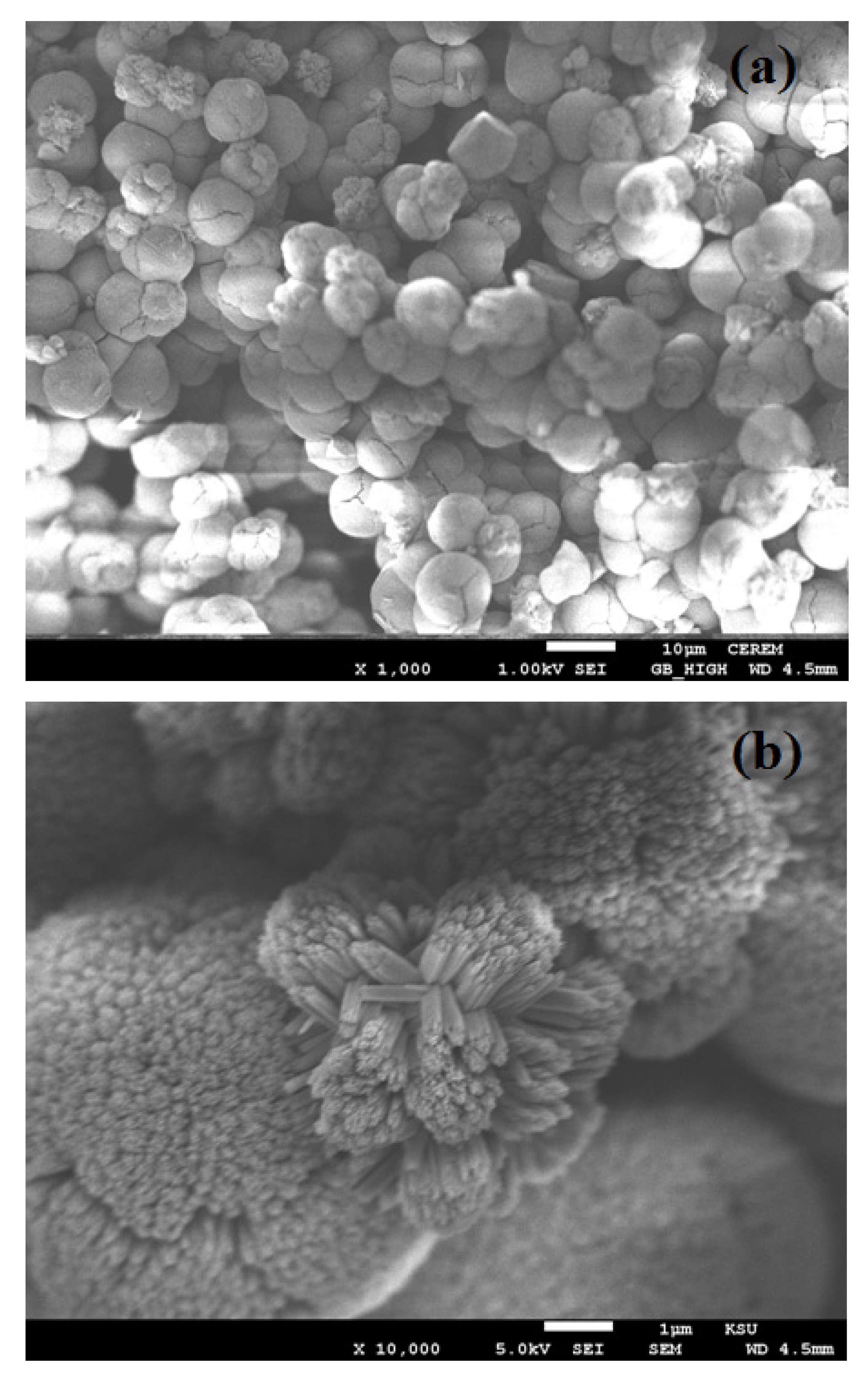
3. Results and Discussion

Figure 2 shows the XRD patterns of TiO2 nanowires grown on FTO glass substrate. Nanowires grown in this work, regardless of substrate used, were found to have the rutile phase by matching between the observed and standard “d” value of the TiO2 nanostructure. XRD data (Figure 1) show a good agreement with the standard TiO2 (PDF file #01-086-0147, P42/mnm, a = b = 4.594 Å and c = 2.958 Å). In XRD spectrum, the respective diffraction peaks corresponding to the FTO are denoted by the symbol “F”.
Figure 2. X-ray diffraction pattern of hierarchical TiO2 structure on fluorine doped tin oxide (FTO) glass substrate.
Materials 08 02376 g002
The field emission scanning electron microscope (FESEM) images of TiO2 nanostructure on FTO glass is shown in Figure 3. From Figure 3a,b we have found that the morphology of TiO2 is a hierarchical structure. It is believed that a hierarchical TiO2 structure (HTS) has three novel levels. The first level, the TiO2, is made up of nano-urchins (NUs); the second level, the NUs, is composed of nanowires (NWs); and the third level, the NWs, is made up of nanoparticles (NPs) [25]. Figure 3a depicts the NUs grown on the FTO glass substrate with an average diameter of 8 µm. Higher magnification of FESEM image Figure 3b reveals the TiO2 nano-urchins is composed of the TiO2 nanowires of average length of 1 µm.
Figure 3. Field emission scanning electron microscopy images of hierarchical TiO2 structure. (a) at low resolution (1000 X); (b) at high resolution (10,000 X).
Materials 08 02376 g003
Figure 4a,b shows the low and high magnification TEM images of CdS QDs nanoparticles deposited by SILAR technique on the TiO2 nanostructure. A clear morphology of CdS QDs nanoparticles, with a size from 4 nm to 6 nm, indicates that CdS QDs are markedly immersed on the surface of TiO2 nanostructure.
The comparison of the absorption spectra of HTS and CdS QDs deposited on the HTS is shown in Figure 5. The immersion of CdS QDs in HTS structure has improved the optical absorbance in the visible region. The absorption edge obtained from the intersection of the sharply decreasing region of a spectrum with its baseline for HTS around 370 nm and shifted to longer wavelength around 520 nm after immersion of CdS QD. Corresponding to this absorption peak, the band gap was calculated to be 2.7 eV. The value reported for CdS in bulk was 2.42 eV [26]. The band gap of CdS particles deposited on HTS films was higher than that of CdS bulk, which indicated that the size of the CdS particles were still within the scale of quantum dot. Estimated from the absorption edge of the absorption spectra, the radius of CdS particles was calculated to be 2.37 nm by using the hyperbolic band model (HBM) equation [27].
R = h 2 E b u l k 2 m * ( E n a n o 2 E b u l k 2 )
where Ebulk is bulk band gap; Enano is band gap of nanomaterial; m* is effective mass of electron in bulk CdS (m* = 0.21mo). Hence the particle size estimated as 2R is 4.74 nm.
Figure 4. Field emission transmission electron microscopy images of CdS QDs in (a) low resolution and 5 nm (b) High resolution 2 nm.
Materials 08 02376 g004
Figure 5. Absorbance spectra of HTS and HTS/CdS QDs.
Materials 08 02376 g005
A new approach implemented the benefits of one-dimensional nanostructures by suitably combining the NU TiO2 and nanoparticles (NP) to construct a hierarchical TiO2 structure (HTS) photoelectrode for the QDSSCs. In particular, the QD provide a high surface area for sufficient QD deposition by SILAR technique, whereas NU TiO2 particles offer a highway for fast charge collection and multiple scattering centers within the photoelectrode. The QDSSCs made of the HTS film exhibited remarkable improvement in power conversion efficiency in comparison to the reference cell made with the NP film [28,29,30].
To evaluate the photovoltaic performance of the HTS, the synthesized products were applied as a photoanode for QDSSC application. The J–V characteristics of the quantum dot sensitized (FTO/HTS/CdS QDs/Pt/FTO) solar cell were measured using a solar simulator. The fourth quadrant of J–V and P–V characteristics are shown in Figure 6. The photocurrent is defined as a current produced under light irradiation due to the generation of free charge carriers by absorption of photons within the depletion layer. Figure 6 demonstrate that the value of J increases with the increasing illumination intensities and the photovoltage value increased up to 0.478 V at 90 mW/cm2 then decreases to 0.46 V at100 mW/cm2. The values of short circuit current density Jsc and open circuit voltage Voc are found to be 1.44 mA/cm2 and 0.46 V under 100 mW/cm2 illuminations, respectively, with an efficiency of 0.27%. As per the literature, we expected the assembly of CdS quantum dots onto hierarchical TiO2 structure for quantum dots sensitized solar cell to give good results. However, with our fabricated cell, we do not observe similar results. The probable reason for obtaining lower efficiency may be due to the QDs embedded in the TiO2 nano urchins matrix provides many pathways, resulting in an increase in injection time.
Figure 6. J–V and P–V characterization of HTS based QDSSC at different intensities of light.
Materials 08 02376 g006
By power-voltage curve, we can take more information about the delivered power to this device. The electric power first increases with the increasing of the voltage and reaches its maximum value and then, decreases and reaches to zero with the further increase of the voltage. The maximum value of power indicates how much the QDSSC can deliver as a maximum power to an external load and is defined as Pmax = IM × VM, where IM is the maximum current and VM is the maximum voltage at each value of illumination intensities.
Figure 7a shows the graph between the short circuit current density Jsc with open circuit voltage Voc. It is seen that the value of Voc increases exponentially with the increase of Isc. This exponentially increasing trend of Voc with Isc obeys the following relation [31,32].
V o c = n k T q l n ( J s c J o + 1 )
where n is the diode ideality factor; k is the Boltzmann’s constant; q is the electric charge; and Jo is the reverse saturation current density. By using the above equation, fitted to the graph of Voc−Jsc, the ideality factor of fabricated cell is found to be 3 [33]. For an ideal p-n junction, the ideality factor is considered to be approximately 1 under room temperature. The probable reasons for larger ideality factors may be due to several defects as well as local non-linear shunts anywhere in the cell area that are responsible the ideality factor value greater than 1 [34].
Figure 7. Photovoltaic performance parameter of HTS based QDSSC (a) Voc−Jsc; (b) JscL; (c) JscVoc plot.
Materials 08 02376 g007
The value of short circuit current density Jsc of the solar cell were obtained from J–V curves under light illumination. In Figure 7b it is observed that there exists a non-linear relation between current and light intensity in the low intensity region. This is due to the large shunt resistance in the device. The linear relation is fully recovered after the light intensity is increased to 40 mW/cm2, indicating that the photo filling effect has saturated the non-radiative recombination center.
Figure 7c show the Jsc−Voc relation plot under different light intensity and reveals that the dark diode property of the fabricated with high series resistance.

4. Conclusions

A novel hierarchical TiO2 structure on transparent conductive FTO glass substrate is synthesized by hydrothermal route. The CdS quantum dots were grown by the successive ionic layer adsorption and reaction deposition method. The investigations of FESEM reveal that HTS consist of spherical nano-urchins and FETEM indicate that CdS QDs are markedly immersed on the surface of TiO2 nanostructure. The QD provide a high surface area and nano-urchins offer a highway for fast charge collection and multiple scattering centers within the photoelectrode, which are responsible for the improvement of power conversion efficiency. We anticipate that nano-urchins consisting of HTS based photoelectrodes could be promising for the fabrication of high efficiency Perovskite quantum dot sensitized solar cell.

Acknowledgments

This project was funded by the National Plan for Science, Technology and Innovation (MAARIFAH), King Abdulaziz City for Science and Technology, Kingdom of Saudi Arabia, Award Number 11NAN 1464-02.

Author Contributions

All the authors contributed significantly for the completions of this manuscript. Mohamed Aslam and Syed Mansoor Ali fabricated solar cell and M. Atif, Amanullah Fatehmulla, W. A. Farooq participated in the experimental as well as data analysis. In short, the whole team contributed in writing up the manuscript.

Conflicts of Interest

The authors declare no conflict of interest.

References

  1. O’Regan, B.; Grätzel, M. A low-cost, high-efficiency solar cell based on dye-sensitized colloidal TiO2 films. Nature 1991, 335, 737–740. [Google Scholar] [CrossRef]
  2. Yin, X.; Xue, Z.S.; Liu, B. Electrophoretic deposition of Pt nanoparticles on plastic substrates as counter electrode for flexible dye-sensitized solar cells. J. Power Sources 2011, 196, 2422–2426. [Google Scholar] [CrossRef]
  3. Song, H.K.; Yoon, J.S.; Won, J.; Kim, H.; Yeom, M.S. New approach to the reduction of recombination in dye-sensitised solar cells via complexation of oxidised species. J. Nanosci. Nanotechnol. 2013, 13, 5136–5141. [Google Scholar] [CrossRef] [PubMed]
  4. Guo, W.X.; Xu, C.; Wang, X.; Wang, S.H.; Pan, C.F.; Lin, C.J.; Wang, Z.L. Rectangular bunched rutile TiO2 nanorod arrays grown on carbon fiber for dye-sensitized solar cells. J. Am. Chem. Soc. 2012, 134, 4437–4441. [Google Scholar] [CrossRef] [PubMed]
  5. Sun, X.M.; Sun, Q.; Li, Y.; Sui, L.N.; Dong, L.F. Effects of calcination treatment on the morphology and crystallinity, and photoelectric properties of all-solid-state dye-sensitized solar cells assembled by TiO2 nanorod arrays. Phys. Chem. Chem. Phys. 2013, 15, 18716–18720. [Google Scholar] [CrossRef] [PubMed]
  6. Kong, J.; Zhou, Z.J.; Li, M.; Zhou, W.H.; Yuan, S.J.; Yao, R.Y.; Zhao, Y.; Wu, S.X. Wurtzite copper-zinc-tin sulfide as a superior counter electrode material for dye-sensitized solar cells. Nanoscale Res. Lett. 2013, 8. [Google Scholar] [CrossRef]
  7. Grätzel, M. Solar energy conversion by dye-sensitized photovoltaic cells. Inorg. Chem. 2005, 44, 6841–6851. [Google Scholar] [CrossRef] [PubMed]
  8. Fan, X.; Chu, Z.Z.; Wang, F.Z.; Zhang, C.; Chen, L.; Chen, Y.; Tang, Y.W.; Zou, D.C. Wire-shaped flexible dye-sensitized solar cells. Adv. Mater. 2008, 20, 592–595. [Google Scholar] [CrossRef]
  9. Lee, M.R.; Eckert, R.D.; Forberich, K.; Dennler, G.; Brabec, C.J.; Gaudiana, R.A. Solar power wires based on organic photovoltaic materials. Science 2009, 324, 232–235. [Google Scholar] [CrossRef] [PubMed]
  10. Tsai, J.K.; Hsu, W.D.; Wu, T.C.; Meen, T.H.; Chong, W.J. Effect of compressed TiO2 nanoparticle thin film thickness on the performance of dye-sensitized solar cells. Nanoscale Res. Lett. 2013, 8. [Google Scholar] [CrossRef]
  11. Wang, D.; Hou, S.C.; Wu, H.W.; Zhang, C.; Chu, Z.Z.; Zou, D.C. Fiber-shaped all-solid state dye sensitized solar cell with remarkably enhanced performance via substrate surface engineering and TiO2 film modification. J. Mater. Chem. 2011, 21, 6383–6388. [Google Scholar] [CrossRef]
  12. Gorer, S.; Hodes, G. Quantum size effects in the study of chemical solution deposition mechanisms of semiconductor films. J. Phys. Chem. 1994, 98, 5338–5346. [Google Scholar] [CrossRef]
  13. Moreels, I.; Lambert, K.; de-Muynck, D.; Vanhaecke, F.; Poelman, D.; Martins, J.C.; Allan, G.; Hens, Z. Composition and size-dependent extinction coefficient of colloidal PbSe quantum dots. Chem. Mater. 2007, 19, 6101–6106. [Google Scholar] [CrossRef]
  14. Shaller, R.D.; Klimov, V.I. High efficiency carrier multiplication in PbSe nanocrystals: Implications for solar energy conversion. Phys. Rev. Lett. 2004, 92. [Google Scholar] [CrossRef]
  15. Michele, P.; Sven, R.; Adam, G.; David, A.K.; Hannah, N.B.; Paolo, M.S.; Daniela, N.; Rodrigo, M.; Assaf, Y.A.; Arie, Z.; et al. TiO2/Cu2O all-oxide heterojunction solar cells produced by spray pyrolysis. Sol. Energy Mater. Sol. Cells 2015, 132, 549–556. [Google Scholar] [CrossRef]
  16. Hu, L.H. Microstructure design of nanoporous TiO2 photoelectrodes for dye-sensitized solar cell modules. J. Phys. Chem. B 2007, 111, 358–362. [Google Scholar] [CrossRef] [PubMed]
  17. Berger, T.; Lana, V.T.; Monllor, S.D.; Gomez, R. An electrochemical study on the nature of trap states in nanocrystalline rutile thin films. J. Phys. Chem. C 2007, 111, 9936–9942. [Google Scholar] [CrossRef]
  18. Qu, J.; Li, G.R.; Gao, X.P. One-dimensional hierarchical titania for fast reaction kinetics of photoanode materials of dye-sensitized solar cells. Energy Environ. Sci. 2010, 3, 2003–2009. [Google Scholar] [CrossRef]
  19. Liao, J.Y.; Lei, B.X.; Chen, H.Y.; Kuang, D.B.; Su, C.Y. Oriented hierarchical single crystalline anatase TiO2 nanowire arrays on Ti-foil substrate for efficient flexible dye-sensitized solar cells. Energy Environ. Sci. 2012, 5, 5750–5757. [Google Scholar] [CrossRef]
  20. Liao, J.Y.; Lei, B.X.; Kuang, D.B.; Su, C.Y. Tri-functional hierarchical TiO2 spheres consisting of anatase nanorods and nanoparticles for high efficiency dye-sensitized solar cells. Energy Environ. Sci. 2011, 4, 4079–4085. [Google Scholar] [CrossRef]
  21. Ohsaki, Y. Dye-sensitized TiO2 nanotube solar cells: Fabrication and electronic characterization. Phys. Chem. Chem. Phys. 2005, 7, 4157–4163. [Google Scholar] [CrossRef] [PubMed]
  22. Zhu, K.; Neale, N.R.; Miedaner, A.; Frank, A.J. Enhanced charge-collection efficiencies and light scattering in dye-sensitized solar cells using oriented TiO2 nanotubes arrays. Nano Lett. 2007, 7, 69–74. [Google Scholar] [CrossRef] [PubMed]
  23. Feng, X.; Shankar, K.; Paulose, M.; Grimes, C.A. Tantalum-doped titanium dioxide nanowire arrays for dye-sensitized solar cells with high open-circuit voltage. Angew. Chem. Int. Ed. 2009, 48, 8095–8098. [Google Scholar] [CrossRef]
  24. Wu, Q.; Wu, B.X.L.; Hua, S.R.; Cheng, Y.S.; Dai, B.K. Hydrothermal fabrication of hierarchically anatase TiO2 nanowire arrays on FTO glass for dye-sensitized solar cells. Sci. Rep. 2013, 3. [Google Scholar] [CrossRef] [PubMed]
  25. Tan, X.; Qiang, P.; Zhang, D.; Cai, X.; Tan, S.; Liu, P.; Mai, W. Three-level hierarchical TiO2nanostructure based high efficiency dye-sensitized solar cells. CrysEngComm 2014, 16, 1020–1025. [Google Scholar] [CrossRef]
  26. Lee, Y.L.; Lo, Y.S. Highly efficient quantum-dot-sensitized solar cell based on co-sensitization of CdS/CdSe. Adv. Funct. Mater. 2009, 19, 604–609. [Google Scholar] [CrossRef]
  27. Nath, S.S.; Choudhury, M.; Gope, G.; Nath, R.K. PVA embedded ZnO quantum dots for methanol sensing. Nanotrends 2010, 8, 1–4. [Google Scholar]
  28. Kong, E.H.; Chang, Y.J.; Park, Y.C.; Yoon, Y.H.; Park, H.J.; Jang, H.M. Sea urchin TiO2-nanoparticle hybrid composite photoelectrodes for CdS/CdSe/ZnS quantum-dot-sensitized solar cells. Phys. Chem. Chem. Phys. 2012, 14, 4620–4625. [Google Scholar] [CrossRef] [PubMed]
  29. Wu, S.J.; Chen, C.Y.; Chen, J.G.; Li, J.Y.; Tung, Y.L.; Ho, K.C.; Wu, C.G. Carbazole containing Ru-based photo-sensitizer for dye-sensitized solar cell. J. Chin. Chem. Soc. 2010, 57, 1127–1130. [Google Scholar] [CrossRef]
  30. Rosenblut, M.L.; Lewis, N.S. Ideal behavior of the open circuit voltage of semiconductor liquid junction. J. Phys. Chem. 1989, 93, 3735–3740. [Google Scholar] [CrossRef]
  31. Hagfeldt, A.; Lindström, H.; Södergren, S.; Lindquist, S.E. Photoelectrochemical studies of colloidal TiO2 films: The effect of oxygen studied by photocurrent transients. J. Electroanal. Chem. 1995, 381, 39–46. [Google Scholar] [CrossRef]
  32. Sheng, X.; Zhao, Y.; Zhai, J.; Jiang, L.; Zhu, D. Electro-hydrodynamic fabrication of ZnO-based dye sensitized solar cells. Appl. Phys. A 2007, 87, 715–719. [Google Scholar] [CrossRef]
  33. Sogabe, T.; Shoji, Y.; Ohba, M.; Yoshida, K.; Tamaki, R.; Hong, H.F.; Wu, C.H.; Kuo, C.T.; Tomic, S.; Okada, Y.; et al. Intermediate band dynamic of quantum dots solar cell in concentrated photovoltaic modules. Sci. Rep. 2014, 4. [Google Scholar] [CrossRef] [PubMed]
  34. Breitenstein, O.; Langenkamp, M.; Rakotoniaina, J.P.; Zettner, J. The imaging of shunts in solar cells by infrared lock-in thermography. In Proceedings of the 17th European Photovoltaic Solar Energy Conference, Munich, Germany, 22–26 October 2001; pp. 1499–1502.

