1. Introduction
Ultra high temperature ceramics (UHTCs) refer to a class of refractory materials with melting temperatures in excess of 3000 °C, such as diborides and carbides of transition metals [
1,
2]. As a member of UHTCs, zirconium diboride (ZrB
2) has been widely attractive for decades. Because of its excellent properties, such as high melting temperature, high thermal conduction, excellent mechanical properties,
etc., ZrB
2 can be operated as leading edges in hypersonic vehicles.
According to previous research, ZrB
2/SiC exhibited excellent ablation resistance against oxyacetylene torch, arc jet or plasma arc [
3,
4,
5]. No obvious mass loss or macroscopic damage appears. Some products, like SiO
2 and ZrO
2, can be detected ona microscopic scale, and have been proved to be helpful to improve ZrB
2/SiC’s ablation resistance [
6,
7]. However, the upper surface of the sample is wholly heated by the above ablation method, and we could only obtain the information of phase and microstructure until the ablated sample cools completely. Longer cooling time contributes to ablation transformation. So some important characterized information has been concealed or disappeared during the cooling process. Researchers only observed that the ablated layer of ZrB
2/SiC was composed by ZrO
2 skeleton and liquid SiO
2 [
8,
9]. The real process and details of the formation of oxidation product, especially ZrO
2, are still unknown.
If the information of phase and microstructure under high temperature can be preserved by fast cooling, the real transformation will be easily observed at room temperature. Because of thistheory, the high intensity laser ablation method with rapid heating rate was utilized. The local temperature of ZrB
2/SiC at the spot center can reach thousands of degrees instantaneously at the beginning of laser irradiating. When laser loading stops, the sample can cool down rapidly to room temperature (which is similar to quenching), since the heating area is very small and the emissivity and conductivity of ZrB
2/SiC are very high [
10,
11].
In this paper, ZrB2/20 vol % SiC composite (donated as ZS hereafter) was prepared and irradiated by high intensity continuous laser. The phase and microstructure evolution of ZrB2/SiC was investigated.
2. Results and Discussion
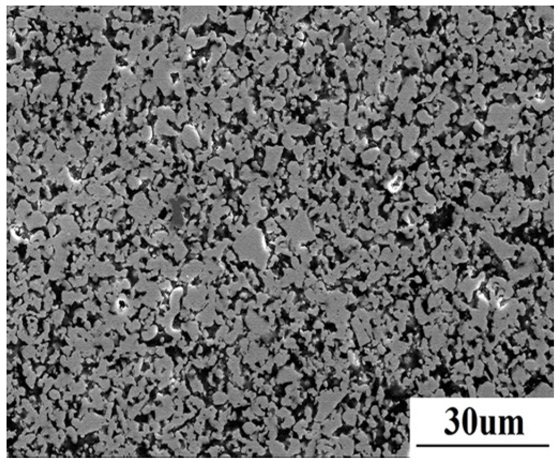
Figure 1 shows the polished surface microstructure of the as-sintered material. ZrB
2 with grain size of about 5 μm is present as a grey matrix, while the dark SiC homogeneously distributes in the matrix.
Figure 1.
The microstructure of as-sintered ZrB2/SiC composite.
Figure 1.
The microstructure of as-sintered ZrB2/SiC composite.
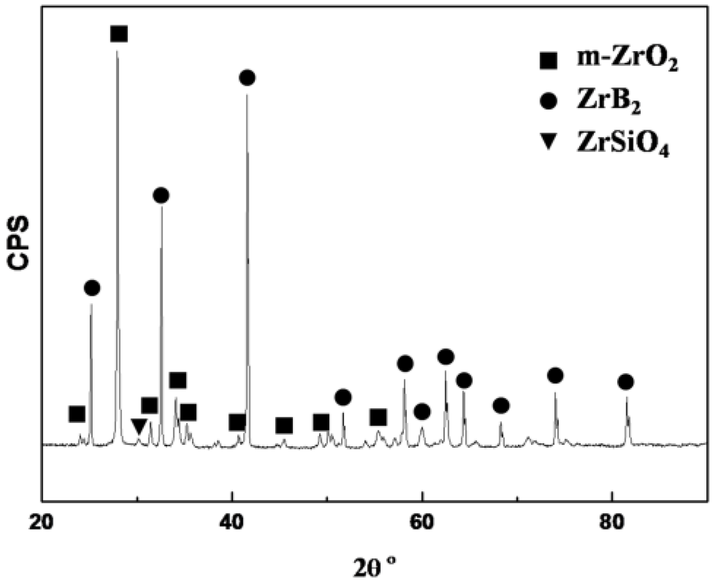
The X-ray diffraction (XRD) result of the ZrB
2/SiC surface after laser ablation for 20 s is shown in
Figure 2. According to the XRD, m-ZrO
2 and ZrB
2 are the major phases on the surface. It reveals that some ZrB
2 are oxidized into ZrO
2 while parts of ZrB
2 are not oxidized at all. No peaks of SiO
2 can be observed on the spectrum, because SiO
2 is amorphous on the surface. However, small amounts of ZrSiO
4 aredetected, as shown in the spectrum. This proves that SiO
2 forms, and that parts of ZrO
2 dissolve into SiO
2 to form ZrSiO
4.
Figure 2.
X-ray diffraction (XRD) of the sample surface afterablation for 20 s.
Figure 2.
X-ray diffraction (XRD) of the sample surface afterablation for 20 s.
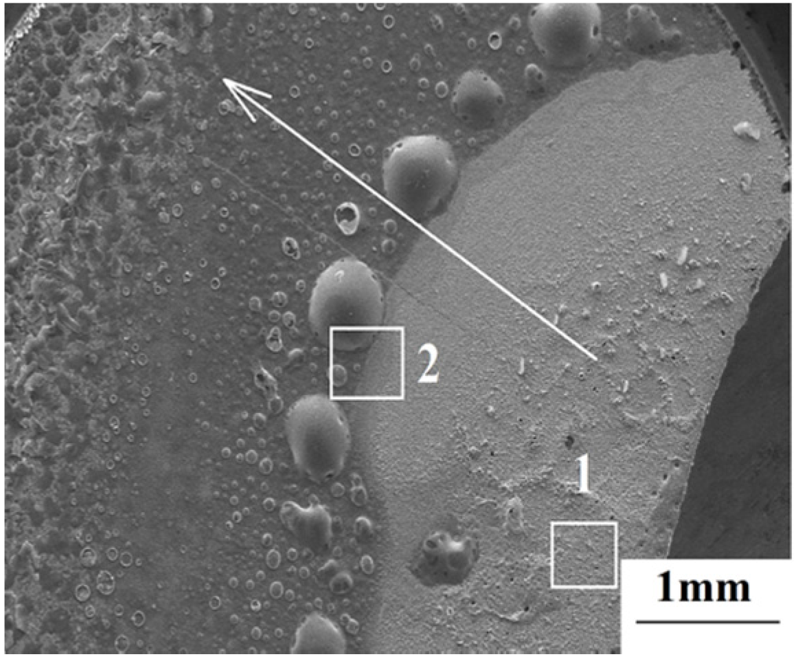
The surface macrostructure of ZrB
2/SiC after laser ablation for 20 s is shown in
Figure 3. Since the local heating of the laser induces extremely high temperature at the spot center, a great temperature gradient is generated along the radial direction, shown bythe arrow in
Figure 3. Significant differences in ablation behavior between area 1 and area 2 were detected.
Figure 3.
The surface macrostructure of the sample after ablation for 20 s.
Figure 3.
The surface macrostructure of the sample after ablation for 20 s.
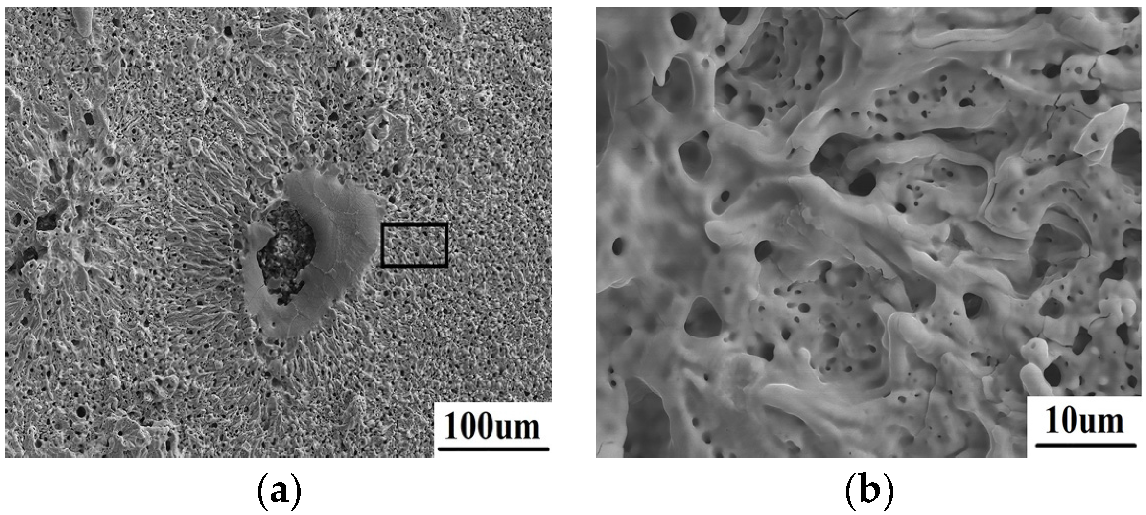
The surface morphology of area 1 after laser ablation is shown in
Figure 4. From
Figure 4a, the surface performs a porous structure. The energy dispersive spectroscopy (EDS) result reveals that only ZrO
2 exists on the surface; neither ZrB
2 nor SiC can be detected. A typical flushing morphology is clearly shown as
Figure 4b. It should be attributed to the liquid splashing and the following rapid solidification. This means that the oxidized ZrO
2 in this region has been totally melted during laser ablation. Meanwhile, SiC is totally decomposed because the temperature here is higher than its decomposition point of 2300 °C.
Figure 4.
The microscopic morphology of area 1 (a) with a typical flushing morphology (b).
Figure 4.
The microscopic morphology of area 1 (a) with a typical flushing morphology (b).
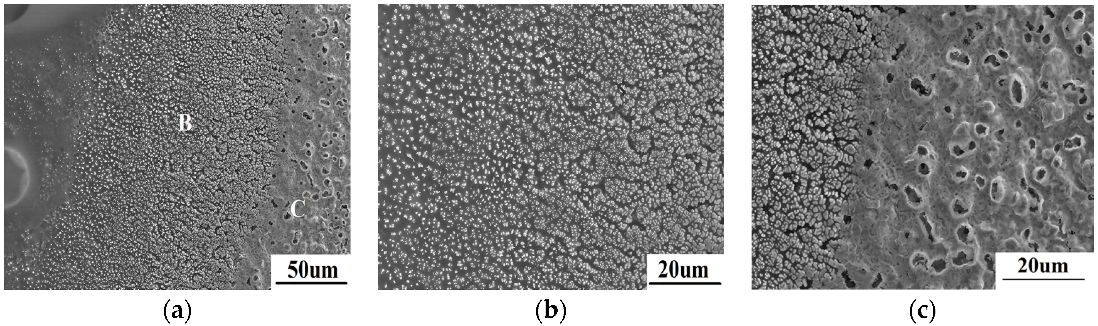
The different microstructure in area 2 is shown in
Figure 5. According to
Figure 5a, lots of white or dark grey particles implant in amorphous substance. Based on the EDS result as shown in
Table 1, the particles are ZrO
2 while the amorphous substance is SiO
2. This also can be confirmed by the XRD result shown in
Figure 2. The region shown in
Figure 5b is farther fromthe spot center than the region shown in
Figure 5c. As can be seen in
Figure 5b, very fine sub-micron ZrO
2 distributes evenly in amorphous SiO
2. With the temperature increases from left to right in
Figure 5b, amorphous SiO
2 reduces gradually, while the quantity and size of ZrO
2 particles increase gradually. In
Figure 5c, amorphous SiO
2 is much lower, even almost disappearing at the right side, which results from the evaporation of SiO
2. Moreover, ZrO
2 grains close to the spot center grow gradually, and can even be seen to sinter obviously.
Table 1.
The energy dispersive spectroscopy (EDS) results of area B and C in
Figure 2.
Table 1.
The energy dispersive spectroscopy (EDS) results of area B and C in Figure 2.
| Elements | Area B | Area C |
|---|
| Weight Ratio % | Atomic Ratio % | Weight Ratio % | Atomic Ratio % |
|---|
| O K | 36.32 | 67.85 | 26.52 | 66.30 |
| Si K | 15.32 | 16.31 | 1.51 | 2.15 |
| Zr L | 48.36 | 15.85 | 71.97 | 31.55 |
Figure 5.
The microscopic morphology of area 2 (a) and the further amplified morphology of region B (b) and C (c).
Figure 5.
The microscopic morphology of area 2 (a) and the further amplified morphology of region B (b) and C (c).
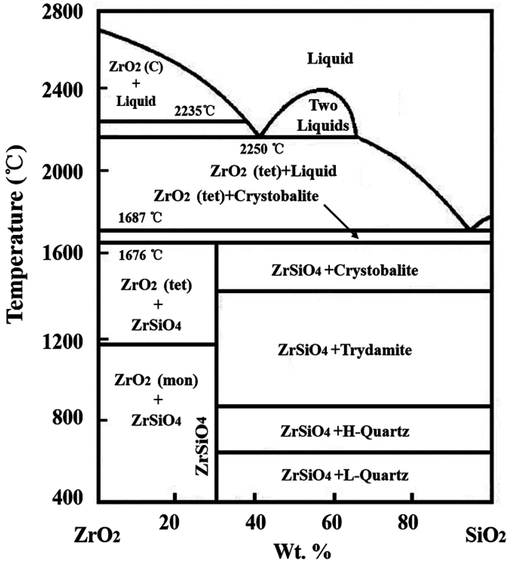
According to the equilibrium phase diagram of ZrO
2-SiO
2 shown as
Figure 6 [
12], the melting temperature (2700 °C) of ZrO
2 can be decreased by liquid SiO
2, while ZrO
2 has high solubility, about 43.3% in SiO
2 at 2235 °C. With increasing temperature, the solubility of ZrO
2 will increase gradually. When laser begins to irradiate on the material, the surface temperature soars up rapidly. A large number of ZrB
2 are oxidized into ZrO
2 between 600–700 °C. Meanwhile, SiC transforms into SiO
2 at 1200 °C, and SiO
2 exhibits as a liquid above 1400 °C. When the temperature approaches 1687 °C, the oxidized ZrO
2 begins to dissolve into SiO
2. SiO
2 is unstable when the temperature is higher than 1800 °C [
13]. The evaporation of SiO
2 at high temperature makes the ZrO
2 solubility decrease, so the extremely fine ZrO
2 grains precipitate. With the evaporation proceeding, the solubility of ZrO
2 dissolved into SiO
2 significantly decreases. A lot of ZrO
2 will precipitate from liquid SiO
2 to form the morphology shown in
Figure 5b. As precipitated ZrO
2 is still subject to intense high temperature, fine ZrO
2 grains with strong activity gradually grow up and sinter together for a short time to form the morphology as shown in
Figure 5c. Therefore, the processing of ZrO
2 dissolution and precipitation is the main transformation mechanism during ablation when liquid SiO
2 is present.
Figure 6.
Thermal equilibrium phase diagram of SiO2-ZrO2.
Figure 6.
Thermal equilibrium phase diagram of SiO2-ZrO2.
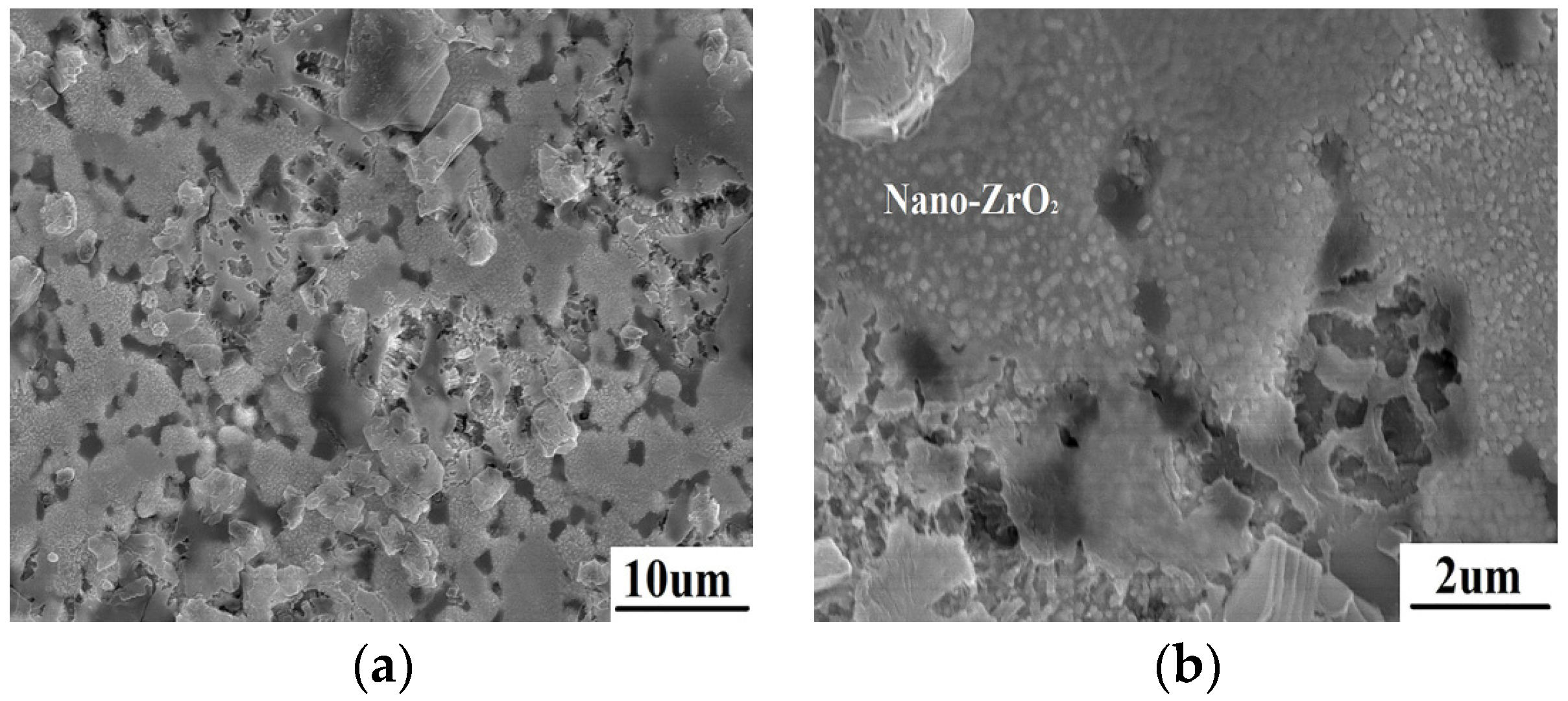
The surface microstructure of ZrB
2/SiC at the edge is shown in
Figure 7. The temperature is lower than 1200 °C in this region away from the spot center. SiC oxidation and liquid SiO
2 are not observed on the surface. The morphology of ZrB
2 has changed because of oxidation. A lot of nano-crystals closely pack on the surface. This is proved to be ZrO
2 according to the EDS result. This indicates that ZrB
2 is directly oxidized into nano-ZrO
2. The results reveal that there is another formation mechanism of ZrO
2 during ablation when liquid SiO
2 is absent.
Figure 7.
The morphology of ZrB2/SiC at the edge after ablation (a) with nano ZrO2 crystals packing on the surface (b).
Figure 7.
The morphology of ZrB2/SiC at the edge after ablation (a) with nano ZrO2 crystals packing on the surface (b).
3. Experimental Section
The ZS composite was prepared using commercial powders listed as follows: ZrB2 (Alfa Aesar Ward Hill, MA, USA, 99.0%, particlesize ~50 μm); SiC (Alfa Aesar, 99.5%, particlesize 1–2 μm). The raw powders were accurately weighted by volume ratioof 4:1 and milled for 6 h in ethanol using zirconia milling media. The mixture powders were sintered by spark plasma sintering technology (SPS, DR. SINTER type 3.20, Fuji Electronic Industrial Co. Ltd., Kanagawa, Japan) at 1750 °C for 5 min with a rate of 200 °C/min. An axial pressure of 50 MPa was applied during the whole process.
The laser irradiation experiment in this paper was carried out by using ytterbium laser system (YLS-2000) (IPG Photonics Co. Ltd., Pittsfiels, MA, USA), with 1070 nm wave-length in atmospheric environment. The spot size of the Gaussianlaser was set as about 10 mm. The power density at the spot center reached 20 MW/m2 in Gaussian laser, and the duration time was 20 s. The dimensions of the ablation specimen were Φ25 mm × 3 mm.
The phase of the sample surface after ablation was detected by X-ray diffraction (XRD, X’pert PRO MPD, PANalytical B.V. Co. Ltd., Amsterdam, The Netherlands, Cu Kα). The surface microstructures of the sample before and afterablation were examined by scanning electron microscope (SEM, Philips S-4800, Hitachi Ltd., Yokohama, Japan). The composition of the sample was identified by energy dispersive spectroscopy (EDS, Oxford Instruments Co. Ltd., Oxfordshire, UK).


