Experimental Study on the Electrochemical Anti-Corrosion Properties of Steel Structures Applying the Arc Thermal Metal Spraying Method


Abstract
:1. Introduction
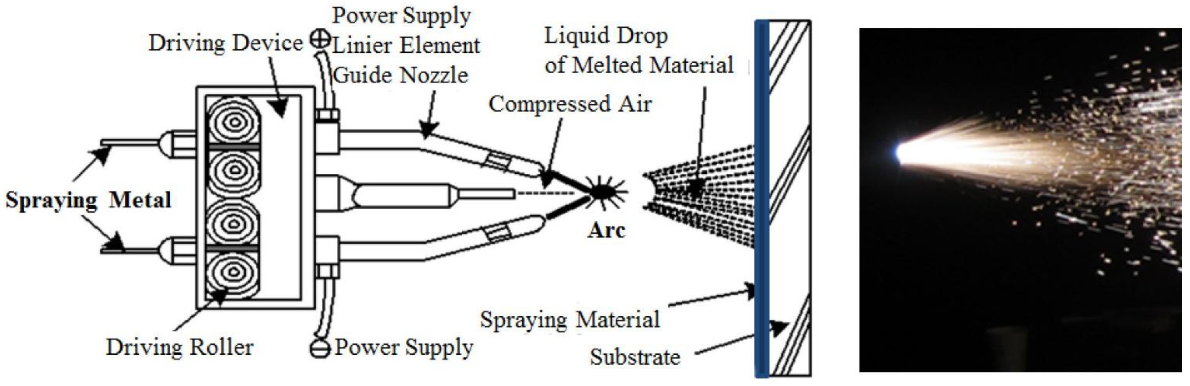
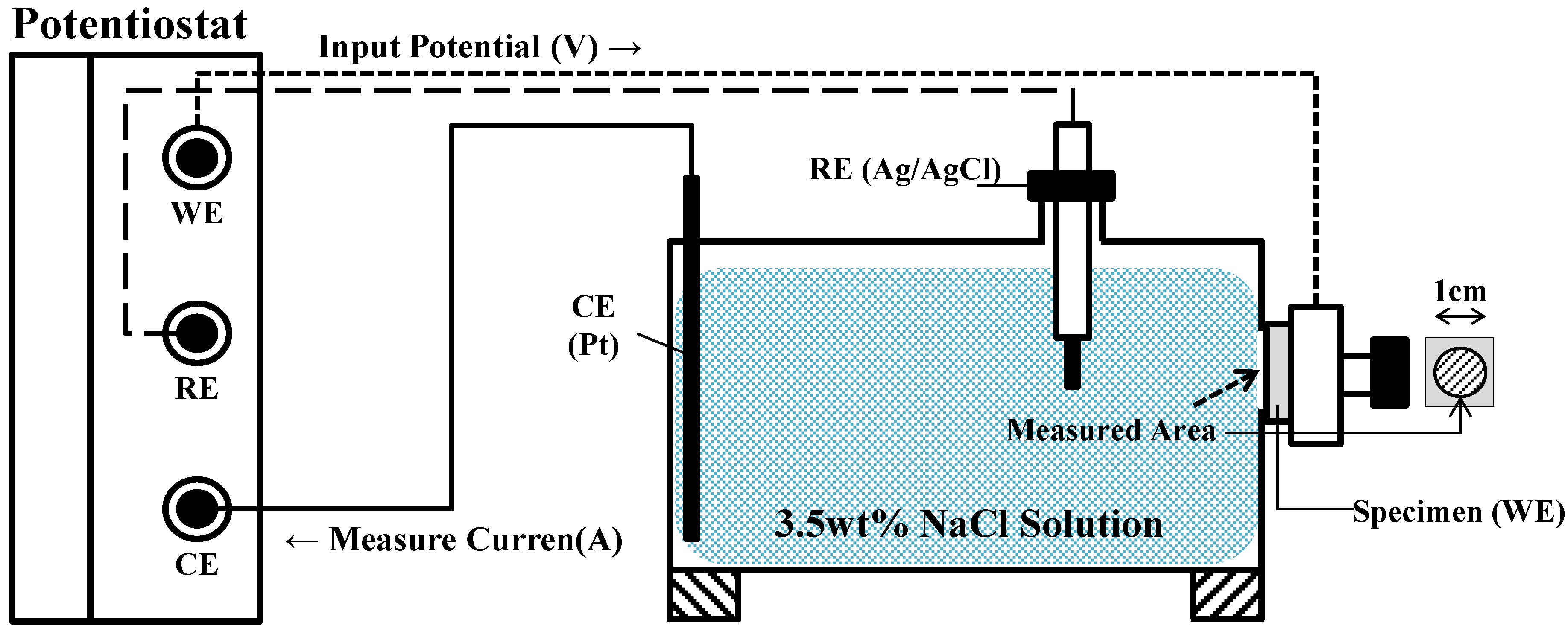
2. Experiments

| No. | Specimen Name | Specimens for Electrochemical Test | Epoxy Sealing Coating | Types of Spraying Metal | Anti-Corrosion Method |
|---|---|---|---|---|---|
| 1 | NP | Non-painted specimen | No | - | - |
| 2 | HDG | Hot dip galvanizing (zinc) 400 g/m2 | No | - | Plating |
| 3 | Z100-NS | Zn (mass 100%) | No | Zn–Zn | Arc thermal metal spray |
| 4 | Z100-S | Zn (mass 100%) | Yes | Zn–Zn | |
| 5 | A100-NS | Al (mass 100%) | No | Al–Al | |
| 6 | A100-S | Al (mass 100%) | Yes | Al–Al | |
| 7 | Z73-A27-NS | Zn–Al (mass 27%) | No | Zn–Al | |
| 8 | Z73-A27-S | Zn–Al (mass 27%) | Yes | Zn–Al | |
| 9 | Z65-S35-NS | Zn–Sn (mass 35%) | No | Zn·Sn–Zn·Sn | |
| 10 | Z65-S35-S | Zn–Sn (mass 35%) | Yes | Zn·Sn–Zn·Sn | |
| 11 | A95-M5-NS | Al–Mg (mass 5%) | No | Al·Mg–Al·Mg | |
| 12 | A95-M5-S | Al–Mg (mass 5%) | Yes | Al·Mg–Al·Mg | - |
| Common items | Steel plate: SS41, 15 mm × 15 mm × 1.6 mm thickness; experimental area: 0.78 cm2 Steel surface treatment: grit blast | ||||


| No. | Specimen Name | SEM Image |
|---|---|---|
| 1 | NP | 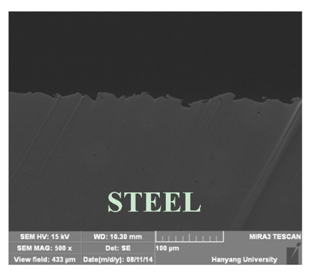 |
| 2 | HDG | 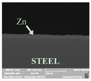 |
| 3 | Z100-NS | 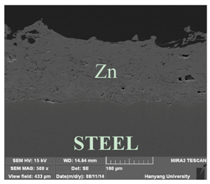 |
| 4 | A100-NS | 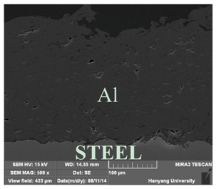 |
| 5 | Z73-A27-NS | 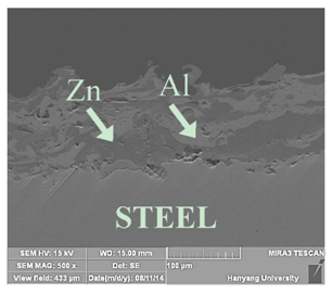 |
| 6 | Z73-A27-S | 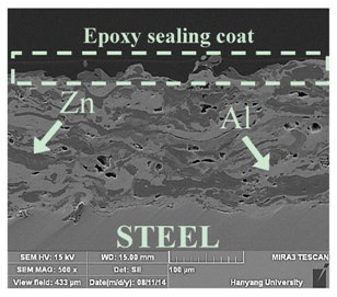 |
| 7 | Z65-S35-NS |  |
| 8 | A95-M5-NS | 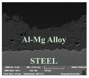 |
3. Discussion
3.1. Experimental Results
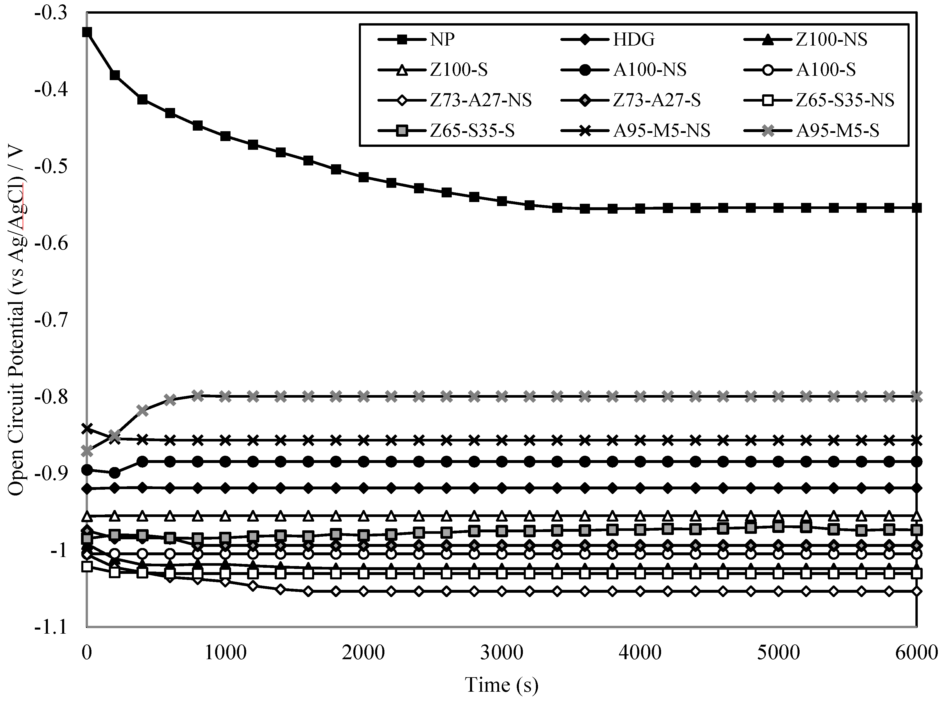
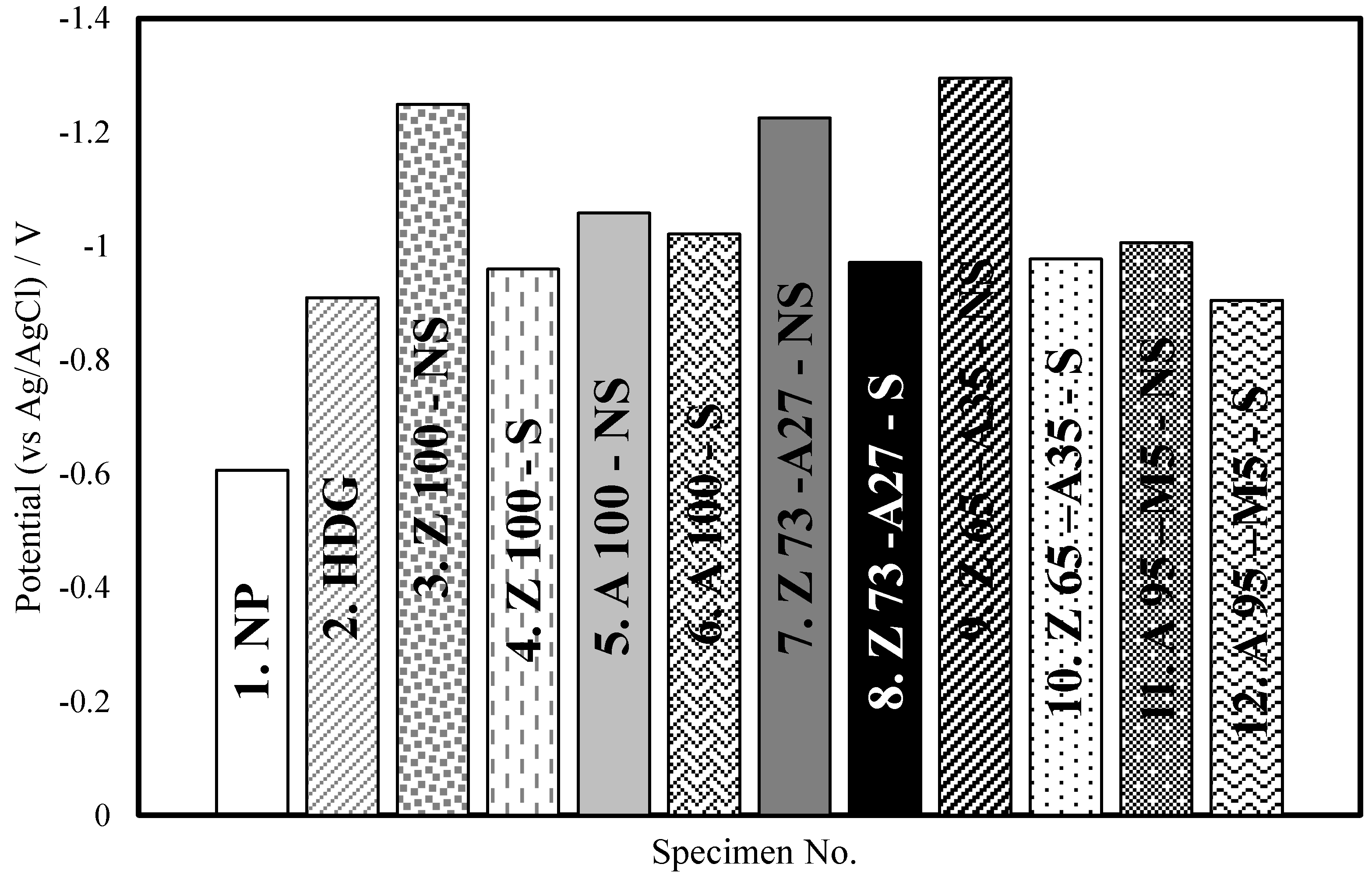
| No. | Specimen Name | Open Circuit Potential (V) | Corrosion Potential (V) | Relative Corrosion Rate (HDG = 1) |
|---|---|---|---|---|
| 1 | NP | −0.55 | −0.61 | 0.30 |
| 2 | HDG | −0.92 | −0.91 | 1.00 |
| 3 | Z100-NS | −1.03 | −1.25 | 2.27 |
| 4 | Z100-S | −0.98 | −0.96 | 0.98 |
| 5 | A100-NS | −0.99 | −1.06 | 0.34 |
| 6 | A100-S | −0.10 | −1.02 | 0.01 |
| 7 | Z73-A27-NS | −1.05 | −1.23 | 0.19 |
| 8 | Z73-A27-S | −0.98 | −0.97 | 0.02 |
| 9 | Z65-S35-NS | −1.03 | −1.30 | 0.66 |
| 10 | Z65-S35-S | −0.97 | −0.98 | 0.16 |
| 11 | A95-M5-NS | −0.86 | −1.07 | 0.18 |
| 12 | A95-M5-S | −0.80 | −0.91 | 0.001 |
| No. | Specimen Name | Before Exp. | After Exp. | No. | Specimen Name | Before Exp. | After Exp. |
|---|---|---|---|---|---|---|---|
| 1 | NP |  |  | 7 | Z73-A27-NS |  |  |
| 2 | HDG |  |  | 8 | Z73-A27-S |  |  |
| 3 | Z100-NS |  |  | 9 | Z65-S35-NS |  |  |
| 4 | Z100-S |  |  | 10 | Z65-S35-S |  |  |
| 5 | A100-NS |  |  | 11 | A95-M5-NS |  |  |
| 6 | A100-S |  |  | 12 | A95-M5-S |  |  |
3.2. Open Circuit Potential and Corrosion Potential
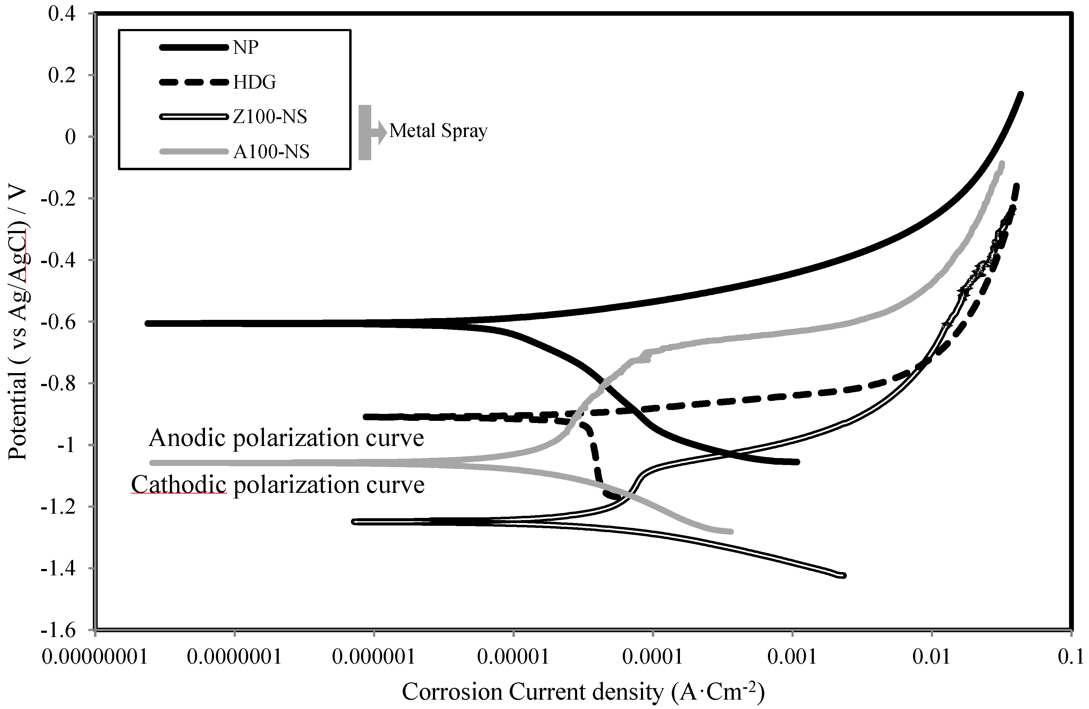
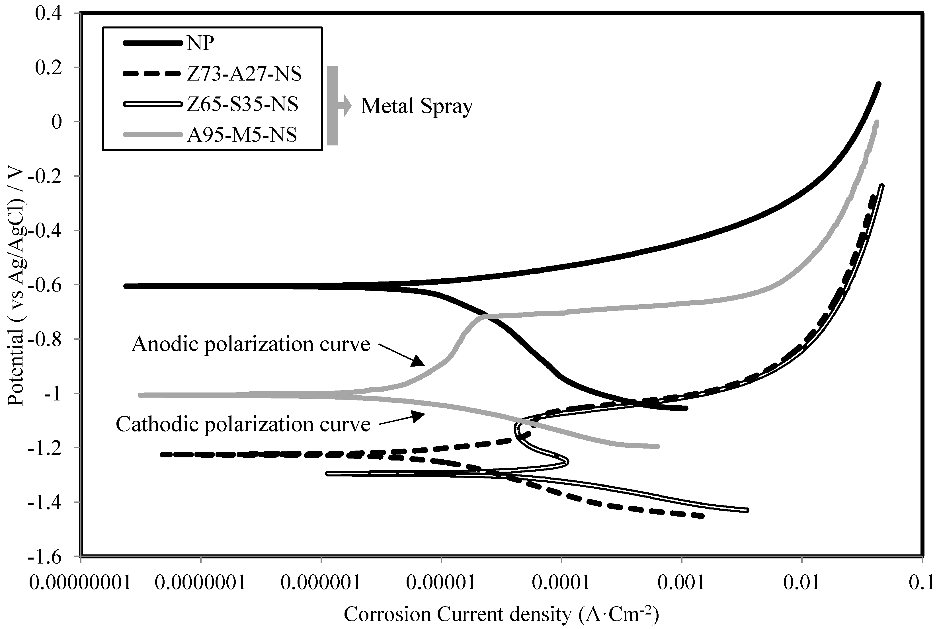
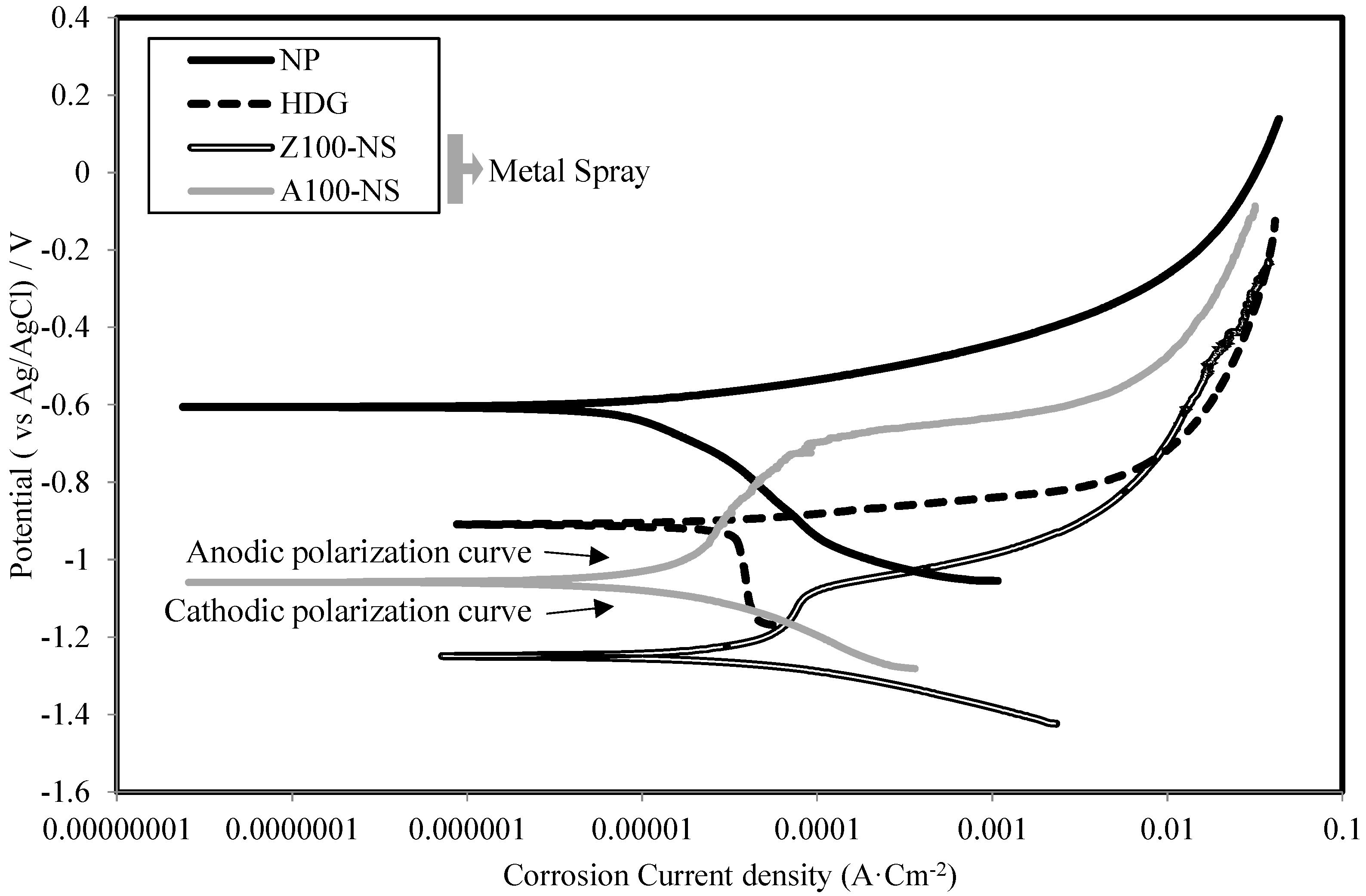
3.3. Polarization Curve


3.4. Corrosion Current Density and Polarization Resistance
| No. | Specimen Name | Corrosion Current Density (µA·cm−2) | Corrosion Rate (µm/y) | Polarization Resistance (KΩ·cm2) |
|---|---|---|---|---|
| 1 | NP | 11.30 | 132.48 | 2.30 |
| 2 | HDG | 29.10 | 439.18 | 0.50 |
| 3 | Z100-NS | 65.90 | 996.33 | 0.35 |
| 4 | Z100-S | 28.4 | 429.02 | 0.74 |
| 5 | A100-NS | 13.60 | 149.87 | 2.46 |
| 6 | A100-S | 0.2 | 2.26 | 521.43 |
| 7 | Z73-A27-NS | 7.91 | 111.49 | 2.63 |
| 8 | Z73-A27-S | 0.63 | 8.85 | 11.45 |
| 9 | Z65-S35-NS | 17.80 | 289.82 | 1.07 |
| 10 | Z65-S35-S | 4.28 | 69.81 | 3.07 |
| 11 | A95-M5-NS | 7.02 | 79.54 | 28.09 |
| 12 | A95-M5-S | 0.02 | 0.29 | 5,255.64 |
4. Conclusions
- The sacrificial anode principle in ATMSM was verified using an electrochemical technique. This is evident from the low values of corrosion current density (Icorr) and high values of polarization resistance (Rp) of specimens with sprayed metal, such as Zn, Al, Zn–Al, Zn–Sn and Al–Mg, compared with Fe alone.
- It is obvious that the corrosion resistance layer generated by applying ATMSM provided a sufficient corrosion resistance with the driving force based on the potential difference of more than approximately 0.60 V between the layer and the base material.
- The corrosion potential difference of the specimens in regards to the presence or absence of epoxy sealing coating in the specimens of Zn–Al metal thermal spraying is about 0.25 V, while in the case of Al–Mg, it is 0.16 V. Thus, the effect of the corrosion resistance of steel by epoxy sealing coating suppresses the dissolution of metals, decreases the corrosion current density and increases the polarization resistance.
- The results of the metal thermal spraying without applying the epoxy sealing coating show that the corrosion current density of the specimen using Al–Mg (95:5) is 7.02 µA·cm−2; the corrosion rate is 79.54 µm/y; and polarization resistance is 28.09 K Ω·cm2. These values in the case of applying the epoxy sealing coating are 0.02 µA·cm−2, 0.29 µm/y and 5255.64 KΩ·cm2, respectively. This is clear evidence that this type of metal thermal spraying has the best performance and exceeds even the Zn–Al type.
Acknowledgments
Author Contributions
Conflicts of Interest
References
- Cocco, V.D.; Iacoviello, F.; Natali, S. Damaging micromechanisms in hot-dip galvanizing Zn based coatings. Theor. Appl. Fract. Mech. 2014, 70, 91–98. [Google Scholar]
- Nishimura, T.; Raman, V. Corrosion prevention of aluminum nanoparticles by a polyurethane coating. Materials 2014, 7, 4710–4722. [Google Scholar] [CrossRef]
- Martinez, S.; Žulj, L.V.; Kapor, F. Disbonding of underwater-cured epoxy coating caused by cathodic protection current. Corros. Sci. 2009, 51, 2253–2258. [Google Scholar] [CrossRef]
- Dong, S.G.; Zhao, B.; Lin, C.J.; Du, R.G.; Hu, R.G.; Zhang, G.X. Corrosion behavior of epoxy/zinc duplex coated rebar embedded in concrete in ocean environment. Constr. Build. Mater. 2012, 28, 72–78. [Google Scholar] [CrossRef]
- Kim, T.S.; Lee, H.S.; Yoo, J.H.; Tae, S.H.; Oh, S.H.; Lim, Y.C.; Lee, S.B. Slip coefficient in high-strength bolt joints coated with corrosion-resistant Zn/Al metal spray method. Mater. Manuf. Proc. 2011, 26, 14–21. [Google Scholar] [CrossRef]
- Guideline of Design and Construction of Melted Zinc Coated Bridge; JSSC (Japanese Society of Steel Construction): Tokyo, Japan, 1997; pp. 57–60.
- Guenbour, A.; Benbachir, A.; Kacemi, A. Evaluation of the corrosion performance of zinc-phosphate-painted carbon steel. Surf. Coat. Technol. 1999, 113, 36–43. [Google Scholar] [CrossRef]
- Cinca, N.; Lima, C.R.C.; Guilemany, J.M. An overview of intermetallics research and application: status of thermal spray coatings. J. Mater. Res. Technol. 2013, 2, 75–86. [Google Scholar] [CrossRef]
- Bettridge, D.F.; Ubank, R.G. Quality control of high-temperature protective coatings. Mater. Sci. Technol. 1986, 2, 232–242. [Google Scholar] [CrossRef]
- Seré, P.R.; Zapponi, M.; Elsner, C.I.; Di Sarli, A.R. Comparative corrosion behaviour of 55 aluminium–zinc alloy and zinc hot-dip coatings deposited on low carbon steel substrates. Corros. Sci. 1998, 40, 1711–1723. [Google Scholar] [CrossRef]
- Sá Brito, V.R.S.; Bastos, I.N.; Costa, H.R.M. Corrosion resistance and characterization of metallic coatings deposited by thermal spray on carbon steel. Mater. Des. 2012, 41, 282–288. [Google Scholar] [CrossRef]
- Kang, C.; Lee, H.; Tae, S.; Cho, Y.; Jang, H.; Lee, S. A prediction of the anti-corrosion life in a steel applying Zn-Al thermal metal spraying method using an electrochemical experiment. Mater. Manuf. Proc. 2011, 26, 22–28. [Google Scholar] [CrossRef]
- Itoh, Y.; Shimizu, Y.; Koyama, A. Durability of steel bridge metallic coating system for combined cyclic corrosion tests with salt water spray and acid rain spray. J. JSCE A 2007, 63, 795–810. [Google Scholar]
- Liu, A. Electrochemical performance and corrosion resistance of Zn-Al pseudo-alloy coatings in chlorine ion-containing environment. J. Univ. Sci. Technol. B. 2012, 34, 1054–1060. [Google Scholar]
- Campo, M.; Carboneras, M.; López, M.D.; Torres, B.; Rodrigo, P.; Otero, E.; Rams, J. Corrosion resistance of thermally sprayed Al and Al/SiC coatings on Mg. Surf. Coat Technol. 2009, 203, 3224–3230. [Google Scholar] [CrossRef]
- Jiang, Q.; Miao, Q.; Liang, W.P.; Ying, F.; Tong, F.; Xu, Y.; Ren, B.L.; Yao, Z.J.; Zhang, P.Z. Corrosion behavior of arc sprayed Al–Zn–Si–RE coatings on mild steel in 3.5 wt% NaCl solution. Electrochim. Acta 2014, 115, 644–656. [Google Scholar] [CrossRef]
- De Rincón, O.; Rincón, A.; Sánchez, M.; Romero, N.; Salas, O.; Delgado, R.; López, B.; Uruchurtu, J.; Marroco, M.; Panosian, Z. Evaluating Zn, Al and Al–Zn coatings on carbon steel in a special atmosphere. Constr. Build. Mater. 2009, 23, 1465–1471. [Google Scholar] [CrossRef]
- Kuroda, S.; Kawakita, J.; Takemoto, M. An 18-year exposure test of thermal-sprayed Zn, Al, and Zn–Al coatings in marine environment. Corrosion 2006, 62, 635–647. [Google Scholar] [CrossRef]
- Jiang, Q.; Miao, Q.; Tong, F.; Xu, Y.; Ren, B.L.; Liu, Z.M.; Yao, Z.J. Electrochemical corrosion behavior of arc sprayed Al–Zn–Si–RE coatings on mild steel in 3.5% NaCl solution. Trans. Nonferr. Met. Soc. China 2014, 24, 2713–2722. [Google Scholar] [CrossRef]
- Xiao, Y.; Jiang, X.; Xiao, Y.; Ma, L. Research on Zn–Al15 thermal spray metal coating and its organic painting composite system protection performance. Procedia Eng. 2012, 27, 1644–1653. [Google Scholar] [CrossRef]
- Asgari, H.; Toroghinejad, M.R.; Golozar, M.A. Effect of coating thickness on modifying the texture and corrosion performance of hot-dip galvanized coatings. Curr. Appl. Phys. 2009, 9, 59–66. [Google Scholar] [CrossRef]
- Dean, S.W. Electrochemical methods of corrosion testing. In Electrochemical Techniques for Corrosion; Baboian, R., Ed.; NACE: Houston, TX, USA, 1977; pp. 52–60. [Google Scholar]
- Stern, M.; Geary, A.L. Electrochemical polarization, No. 1 theoretical analysis of the shape of polarization curves. J. Electrochem. Soc. 1957, 104, 56–57. [Google Scholar] [CrossRef]
© 2014 by the authors; licensee MDPI, Basel, Switzerland. This article is an open access article distributed under the terms and conditions of the Creative Commons Attribution license (http://creativecommons.org/licenses/by/4.0/).
Share and Cite
Choe, H.-B.; Lee, H.-S.; Shin, J.-H. Experimental Study on the Electrochemical Anti-Corrosion Properties of Steel Structures Applying the Arc Thermal Metal Spraying Method. Materials 2014, 7, 7722-7736. https://doi.org/10.3390/ma7127722
Choe H-B, Lee H-S, Shin J-H. Experimental Study on the Electrochemical Anti-Corrosion Properties of Steel Structures Applying the Arc Thermal Metal Spraying Method. Materials. 2014; 7(12):7722-7736. https://doi.org/10.3390/ma7127722
Chicago/Turabian StyleChoe, Hong-Bok, Han-Seung Lee, and Jun-Ho Shin. 2014. "Experimental Study on the Electrochemical Anti-Corrosion Properties of Steel Structures Applying the Arc Thermal Metal Spraying Method" Materials 7, no. 12: 7722-7736. https://doi.org/10.3390/ma7127722
APA StyleChoe, H.-B., Lee, H.-S., & Shin, J.-H. (2014). Experimental Study on the Electrochemical Anti-Corrosion Properties of Steel Structures Applying the Arc Thermal Metal Spraying Method. Materials, 7(12), 7722-7736. https://doi.org/10.3390/ma7127722