Novel Repair Concept for Composite Materials by Repetitive Geometrical Interlock Elements

 and
and
Abstract
:1. Introduction
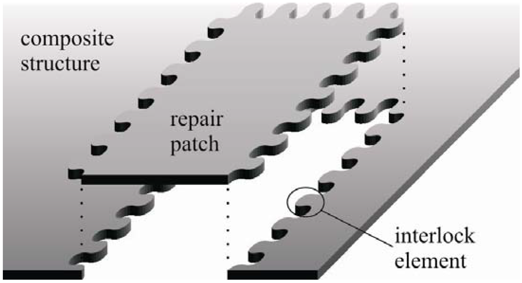
2. Novel Repair Concept
3. Preliminary Design and Simulation Studies

| II | S | W | ||||||||
|---|---|---|---|---|---|---|---|---|---|---|
| A | B | C | D | E | F | |||||
| I | Undercut root area | A | 2 | 3 | 3 | 3 | 3 | 14 | 0.78 | |
| Fiber adapting potential | B | 2 | 2 | 2 | 3 | 3 | 12 | 0.67 | ||
| Contact pressure | C | 1 | 2 | 2 | 3 | 3 | 11 | 0.61 | ||
| Notching effect | D | 1 | 2 | 2 | 3 | 3 | 11 | 0.61 | ||
| Manufacturing | E | 1 | 1 | 1 | 1 | 2 | 6 | 0.33 | ||
| Bonding area | F | 1 | 1 | 1 | 1 | 2 | 6 | 0.33 | ||
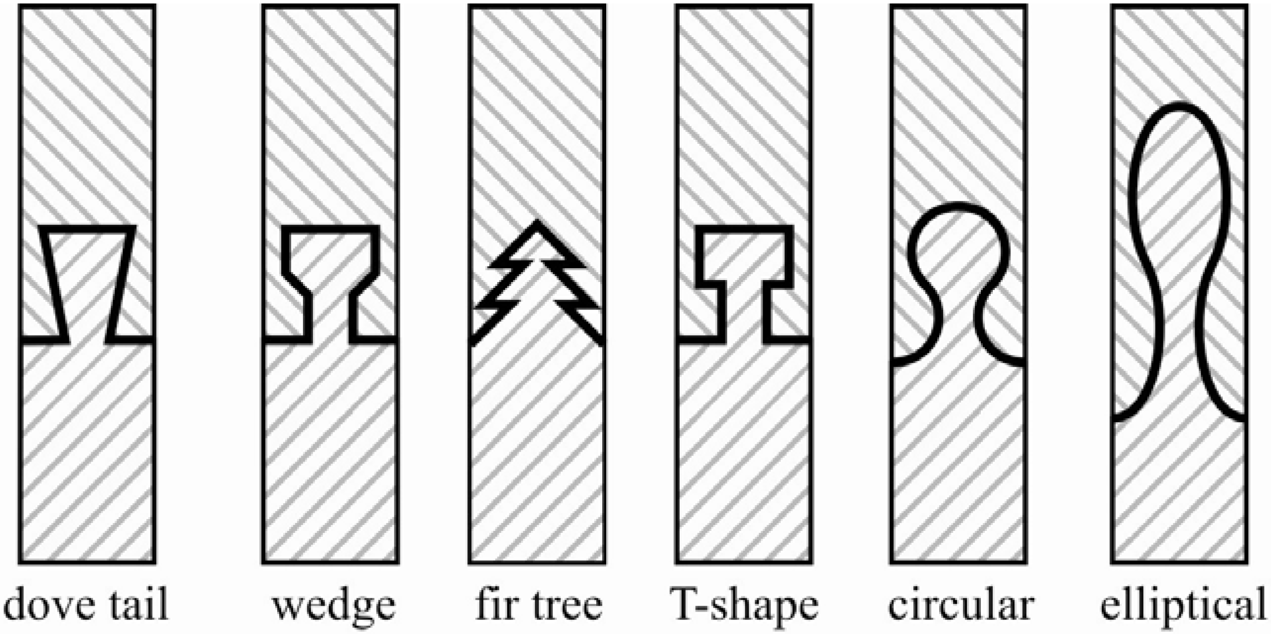
| Dove tail | Wedge | Fir tree | T-shape | Interlock | |||||||||||||||||
|---|---|---|---|---|---|---|---|---|---|---|---|---|---|---|---|---|---|---|---|---|---|
| no mod. | smooth notches | no mod. | smooth notches | thin | thick | thick | thin | circle | elliptic | ||||||||||||
| W |  |  |  |  |  |  |  |  |  |  | |||||||||||
| P | P·W | P | P·W | P | P·W | P | P·W | P | P·W | P | P·W | P | P·W | P | P·W | P | P·W | P | P·W | ||
| A | 0.78 | 4 | 3.1 | 3 | 2.3 | 3 | 2.3 | 2 | 1.6 | 3 | 2.3 | 3 | 2.3 | 3 | 2.3 | 1 | 0.8 | 3 | 2.3 | 3 | 2.3 |
| B | 0.67 | 4 | 2.7 | 4 | 2.7 | 3 | 2.0 | 3 | 2.0 | 2 | 1.3 | 1 | 0.7 | 2 | 1.3 | 1 | 0.7 | 3 | 2.0 | 4 | 2.7 |
| C | 0.61 | 3 | 1.8 | 2 | 1.2 | 3 | 1.8 | 3 | 1.8 | 4 | 2.4 | 4 | 2.4 | 4 | 2.4 | 4 | 2.4 | 3 | 1.8 | 2 | 1.2 |
| D | 0.61 | 1 | 0.6 | 3 | 1.8 | 1 | 0.6 | 3 | 1.8 | 0 | 0.0 | 0 | 0.0 | 1 | 0.6 | 1 | 0.6 | 3 | 1.8 | 4 | 2.4 |
| E | 0.33 | 2 | 0.7 | 3 | 1.0 | 2 | 0.7 | 3 | 1.0 | 0 | 0.0 | 0 | 0.0 | 1 | 0.3 | 1 | 0.3 | 4 | 1.3 | 4 | 1.3 |
| F | 0.33 | 2 | 0.7 | 2 | 0.7 | 3 | 1.0 | 3 | 1.0 | 4 | 1.3 | 4 | 1.3 | 3 | 1.0 | 3 | 1.0 | 2 | 0.7 | 3 | 1.0 |
| 9.6 | 9.7 | 8.4 | 9.2 | 7.4 | 6.8 | 8.1 | 5.8 | 10.0 | 11.0 | ||||||||||||
| Property | Value | |
|---|---|---|
| Fibers | AS4 | |
| Matrix | 3501-6 ep. | |
| Fiber volume fraction | ϕf | 0.60 |
| Longitudinal modulus | E|| | 126 GPa |
| Transverse modulus | E⊥ | 11 GPa |
| In-plane shear modulus | G||⊥ | 6.6 GPa |
| Major Poisson’s ratio | ν | 0.28 |
| Through-thickness Poisson’s ratio | ν⊥⊥ | 0.4 |
| Longitudinal tensile strength | Rt|| | 1950 MPa |
| Longitudinal compressive strength | Rc|| | 1480 MPa |
| Transverse tensile strength | Rt⊥ | 48 MPa |
| Transverse compressive strength | Rc⊥ | 200 MPa |
| In-plane shear strength | R⊥|| | 79 MPa |
| Property | Value | |
|---|---|---|
| Matrix type | MY750 | |
| Young’s modulus | Em | 3.35 GPa |
| Shear modulus | Gm | 1.24 GPa |
| Major Poisson’s ratio | νm | 0.35 |
| Tensile strength | Rtm | 80 MPa |
| Compressive strength | Rcm | 120 MPa |

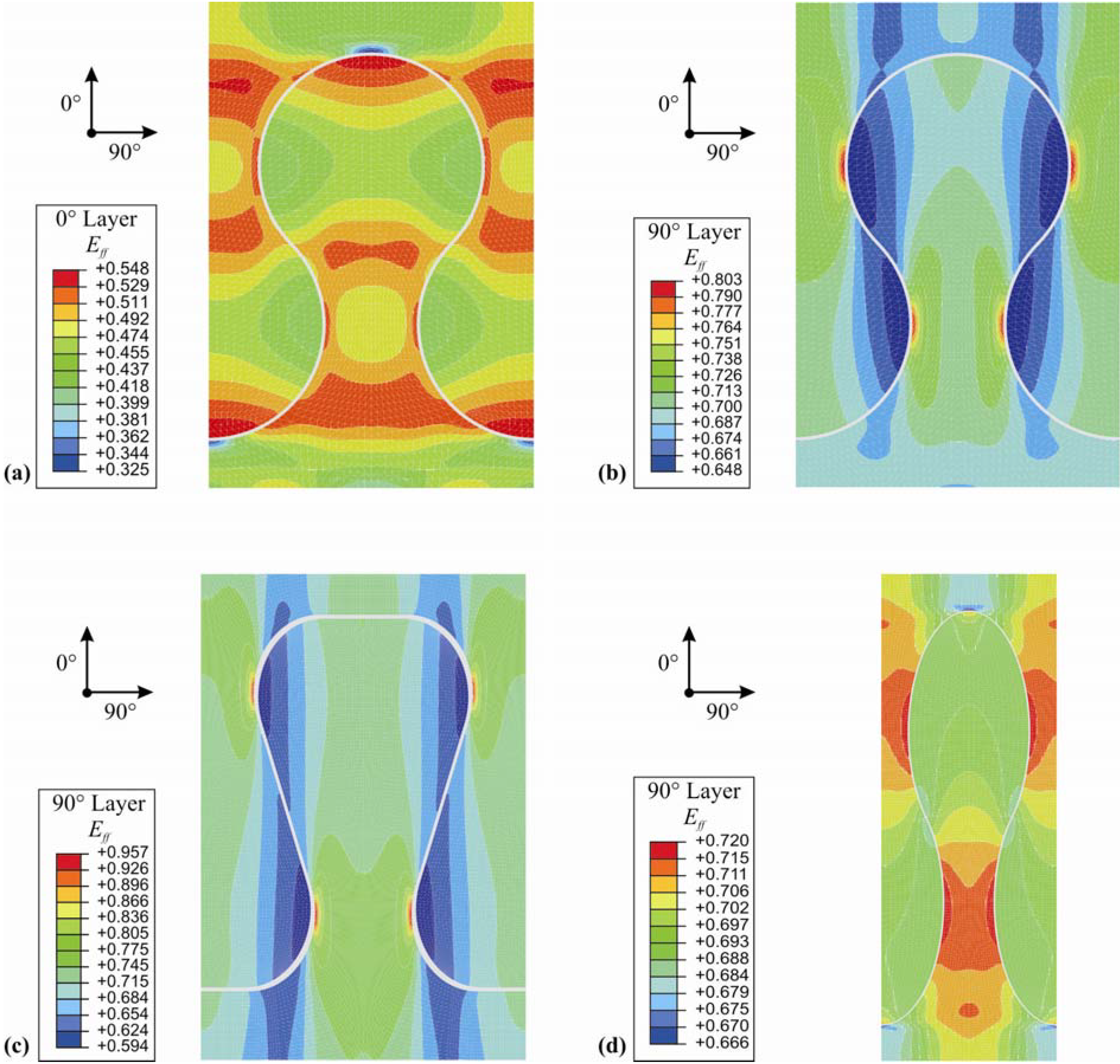
| Geometry | Parameter [mm] | Eff in 0°-direction | Eff in 90°-direction | Sketch |
|---|---|---|---|---|
| Circular interlock | 2.0 | 0.688 | 0.957 |  |
| 2.5 | 0.602 | 0.912 | ||
| 3.0 | 0.581 | 0.846 | ||
| 3.5 | 0.548 | 0.803 | ||
| 4.0 | 0.556 | 0.824 | ||
| 4.8 | 0.695 | 0.966 | ||
| Elliptical interlock | 3.5 / 8.5 | 0.598 | 0.789 | 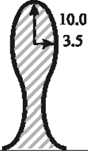 |
| 3.5 / 9.0 | 0.588 | 0.766 | ||
| 3.5 / 9.5 | 0.575 | 0.758 | ||
| 3.5 / 10.0 | 0.558 | 0.719 | ||
| 3.5 / 10.5 | 0.565 | 0.749 | ||
| 3.5 / 11.0 | 0.572 | 0.762 |
| Geometry | Parameters | Eff in 0°-direction | Eff in 90°-direction | Sketch | |
|---|---|---|---|---|---|
| Dove tail (smooth notches) | Opening angle α radius r | 35° 2.25 mm | 0.672 | 0.957 | 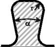 |
| Circular interlock | Radius | 3.5 mm | 0.548 | 0.803 |  |
| Elliptic interlock | Major axis ra Minor axis rb | 10.0 mm 3.5 mm | 0.558 | 0.719 |  |
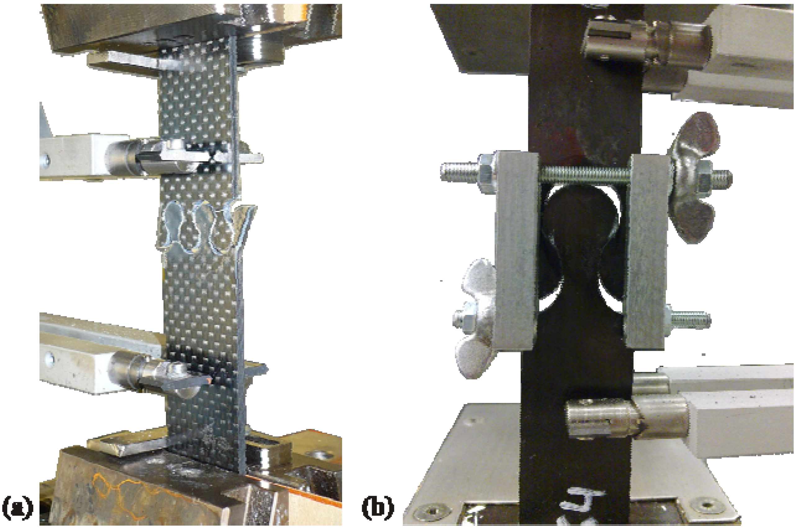
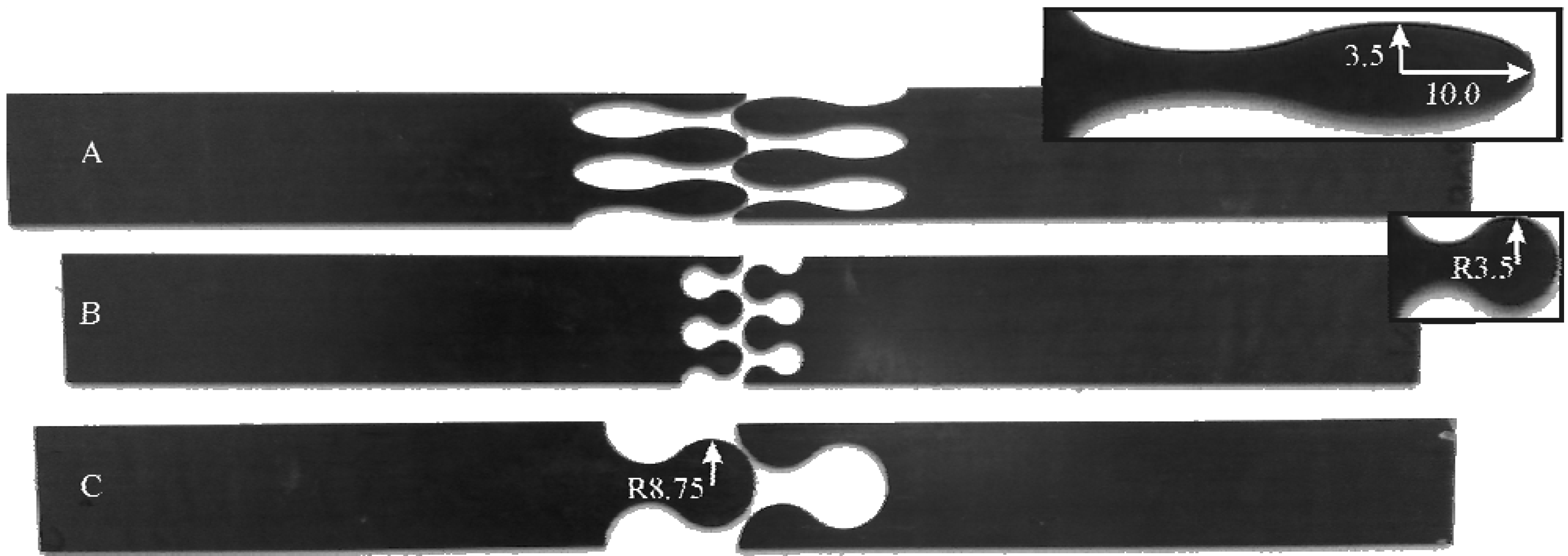
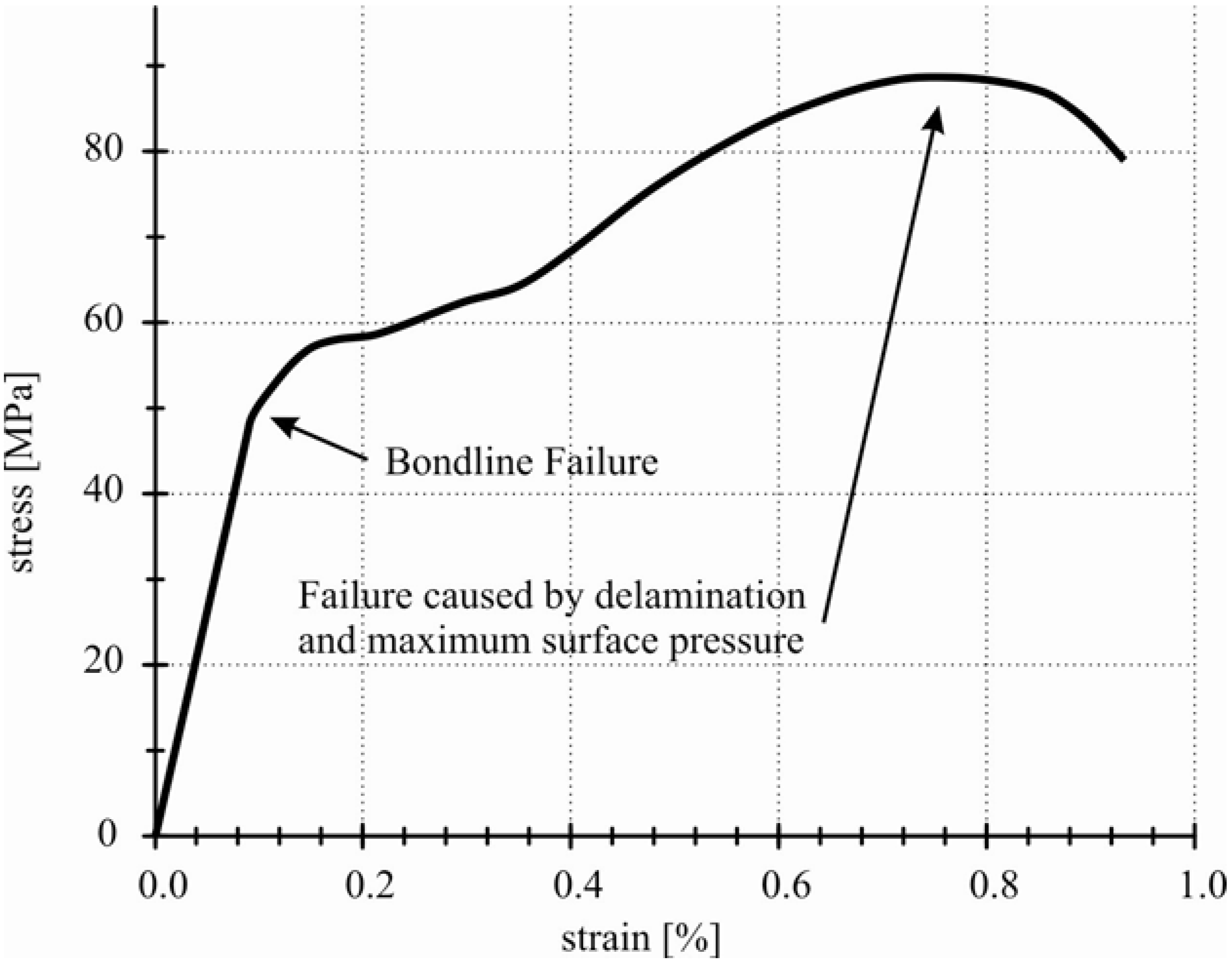
4. Experimental Work


5. Conclusions
Acknowledgments
References
- Oztelcan, C.; Ochoa, O.O.; Martin, J.; Sem, K. Design and analysis of test coupons for composite blade repairs. Compos. Struct. 1997, 37, 185–193. [Google Scholar] [CrossRef]
- Gunnion, A.J.; Herszberg, I. Parametric study of scarf joints in composite structures. Compos. Struct. 2006, 75, 364–376. [Google Scholar] [CrossRef]
- Hu, F.Z.; Soutis, C. Strength prediction of patch-repaired CFRP laminates loaded in compression. Compos. Sci. Technol. 2000, 60, 1103–1114. [Google Scholar] [CrossRef]
- Harmann, A. Optimisation and Improvement of the Design of Scarf Repairs to Aircraft. Ph.D. Dissertation, School of Mechanical and Manufacturing Engineering, The University of New South Wales, Kensington NSW, Austrilia, 2006. [Google Scholar]
- Reimerdes, H.-G.; K#xE4;mpchen, M.; Michaeli, W.; Klocke, F.; Eversheim, W. Reparatur von FVK—Strategien und Deren Praktische Umsetzung. Industrielle Anwendung der Faserverbundtechnik IV. Abschlusskolloquium des DFG Sonderforschungsbereichs 332, Aachen, Germany. April 2001. [Google Scholar]
- Tzetzis, D.; Hogg, P.J. Experimental and finite element analysis on the performance of vacuum-assisted resin infused single scarf repairs. Mater. Des. 2008, 29, 436–449. [Google Scholar] [CrossRef]
- Ahn, S.-H.; Springer, G.S. Repair of Composite Laminates; Department of Aeronautics and Astronautics, Stanford University: Stanford, CA, USA, 2000. [Google Scholar]
- Sherwin, G.R. Non-autoclave processing of advanced composite repairs. Int. J. Adhes. Adhes. 1999, 19, 155–159. [Google Scholar] [CrossRef]
- Cook, B.M. Experimentation and Analysis of Composite Scarf Joint. MS Thesis, Graduate School of Engineering and Management, Air Force Institute of Technology, Wright Ptrsn Afb, OH, USA, 2005. [Google Scholar]
- Baker, A. Bonded composite repair of fatigue-cracked primary aircraft structure. Compos. Struct. 1999, 47, 431–443. [Google Scholar] [CrossRef]
- Engels, H.; Becker, W. Closed-form analysis of external patch repairs of laminates. Compos. Struct. 2002, 56, 259–268. [Google Scholar] [CrossRef]
- Soutis, C.; Duan, D.-M.; Goutas, P. Compressive behaviour of CFRP laminates repaired with adhesively bonded external patches. Compos. Struct. 1999, 45, 289–301. [Google Scholar] [CrossRef]
- Shao, X.J.; Yue, Z.F. Damage simulation of repaired composite laminate with rectangular cut-out. Theor. Appl. Fract. Mech. 2007, 48, 82–88. [Google Scholar] [CrossRef]
- Romilly, D.P.; Clark, R.J. Elastic analysis of hybrid bonded joints and bonded composite repairs. Compos. Struct. 2008, 82, 563–576. [Google Scholar] [CrossRef]
- Harman, A.B.; Wang, C.H. Improved design methods for scarf repairs to highly strained composite aircraft structure. Compos. Struct. 2006, 75, 132–144. [Google Scholar] [CrossRef]
- Wang, C.H.; Gunnion, A.J. On the design methodology of scarf repairs to composite laminates. Compos. Sci. Technol. 2008, 68, 35–46. [Google Scholar] [CrossRef]
- Maier, A.; Günther, G.; Vilsmeier, J. Repair of aircraft structure using ‘hard’ composite patches. In Proceedings of the 9th International Conference on Composite Materials (ICCM 9), Madrid, Spain, 12–16 July 1993; pp. 478–483.
- Baker, A. Development of a Hard-Patch Approach for Scarf Repair of Composite Structure; Technical Report; Defence Science and Technology Organisation (DSTO), Department of Defence, Australian Govenment: Australia, June 2006. [Google Scholar]
- Zaremba, D.; Biskup, C.; Heber, T.; Weckend, N.; Hufenbach, W.; Adam, F.; Bach, F.-W.; Hassel, T. Experimental evaluation of jetting methods for the surface preparation of fiber-reinforced plastics. In Proceedings of the 11th International Conference on Management of Innovative Technologies and 2nd International Conference on Sustainable Life in Manufacturing, Fiesa, Slovenia, 25–27 September 2011; pp. 91–96.
- Cuntze, R.G.; Freund, A. The predictive capability of failure mode concept-based strength criteria for multidirectional laminates. Compos. Struct. 2004, 64, 343–377. [Google Scholar]
© 2011 by the authors; licensee MDPI, Basel, Switzerland. This article is an open access article distributed under the terms and conditions of the Creative Commons Attribution license (http://creativecommons.org/licenses/by/3.0/).
Share and Cite
Hufenbach, W.; Adam, F.; Heber, T.; Weckend, N.; Bach, F.-W.; Hassel, T.; Zaremba, D. Novel Repair Concept for Composite Materials by Repetitive Geometrical Interlock Elements. Materials 2011, 4, 2219-2230. https://doi.org/10.3390/ma4122219
Hufenbach W, Adam F, Heber T, Weckend N, Bach F-W, Hassel T, Zaremba D. Novel Repair Concept for Composite Materials by Repetitive Geometrical Interlock Elements. Materials. 2011; 4(12):2219-2230. https://doi.org/10.3390/ma4122219
Chicago/Turabian StyleHufenbach, Werner, Frank Adam, Thomas Heber, Nico Weckend, Friedrich-Wilhelm Bach, Thomas Hassel, and David Zaremba. 2011. "Novel Repair Concept for Composite Materials by Repetitive Geometrical Interlock Elements" Materials 4, no. 12: 2219-2230. https://doi.org/10.3390/ma4122219
APA StyleHufenbach, W., Adam, F., Heber, T., Weckend, N., Bach, F.-W., Hassel, T., & Zaremba, D. (2011). Novel Repair Concept for Composite Materials by Repetitive Geometrical Interlock Elements. Materials, 4(12), 2219-2230. https://doi.org/10.3390/ma4122219