
Comparative Study on Strengths of Ready-to-Assemble and Eccentric Furniture Joint

Abstract
:1. Introduction
2. Materials and Methods
2.1. Material
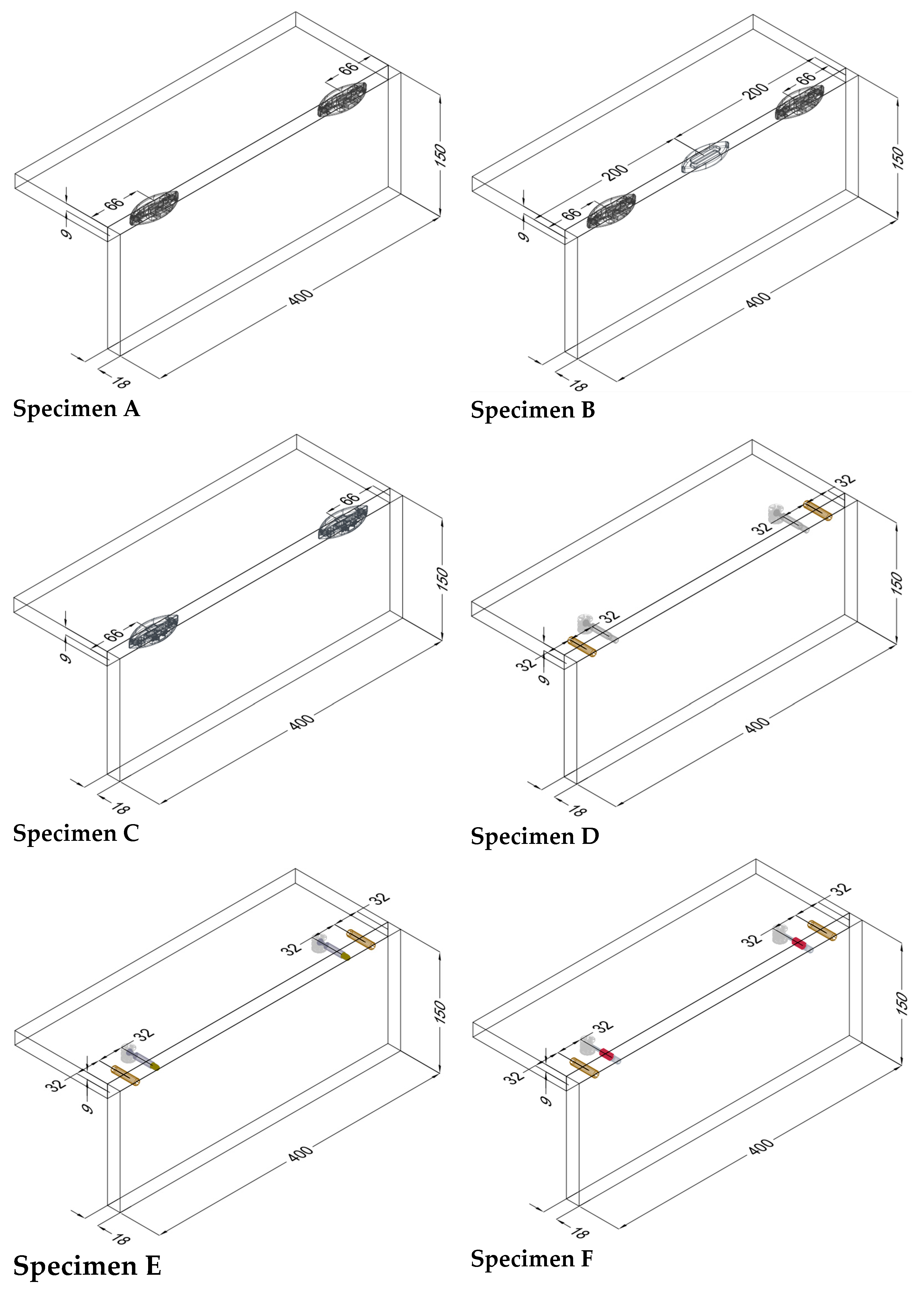
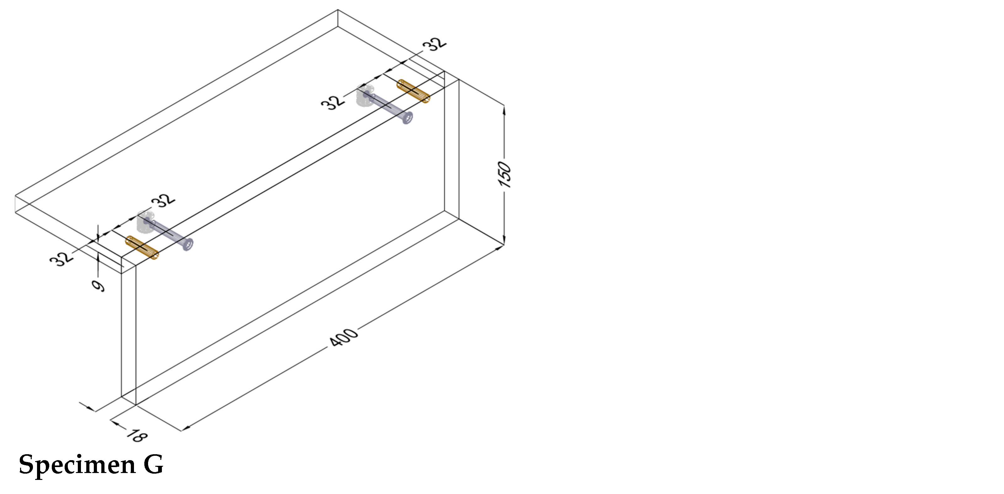
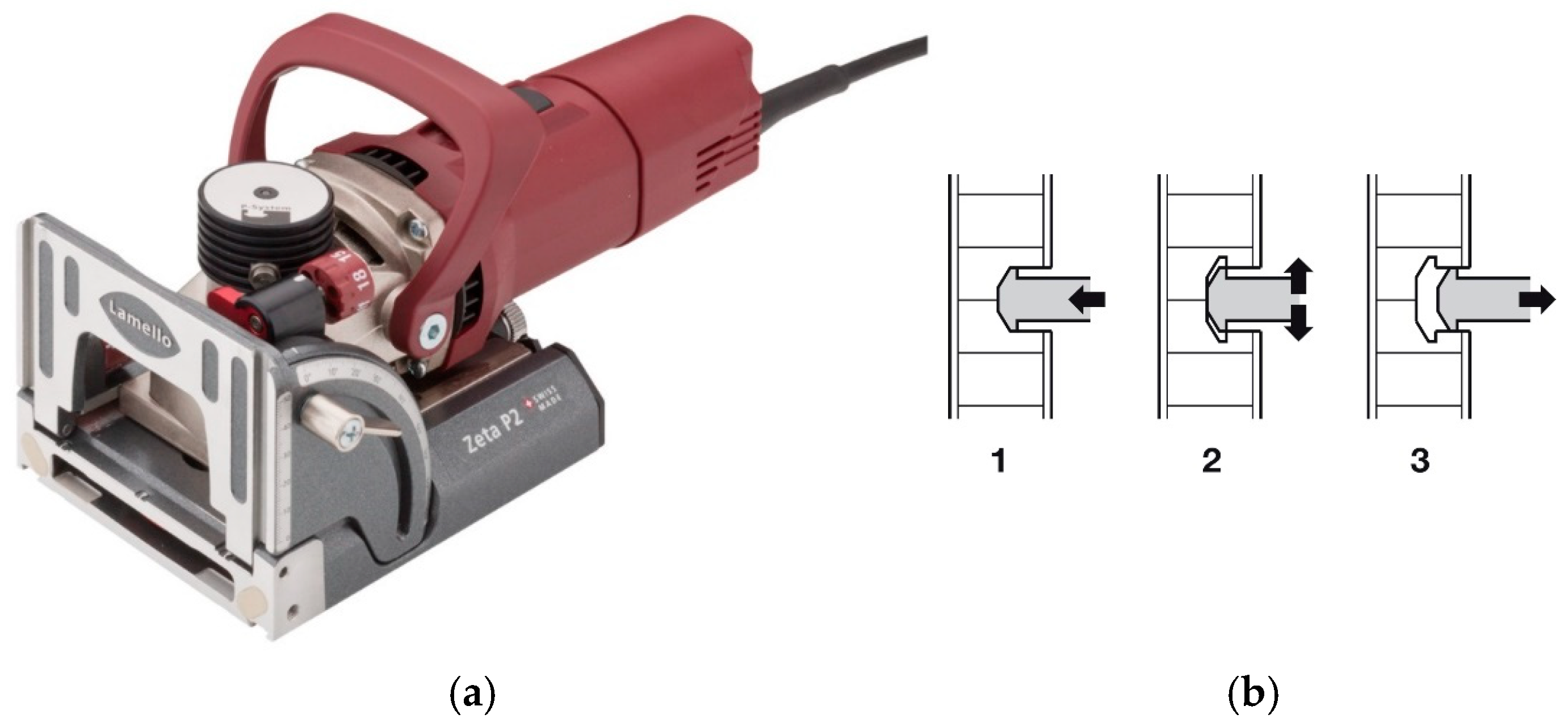
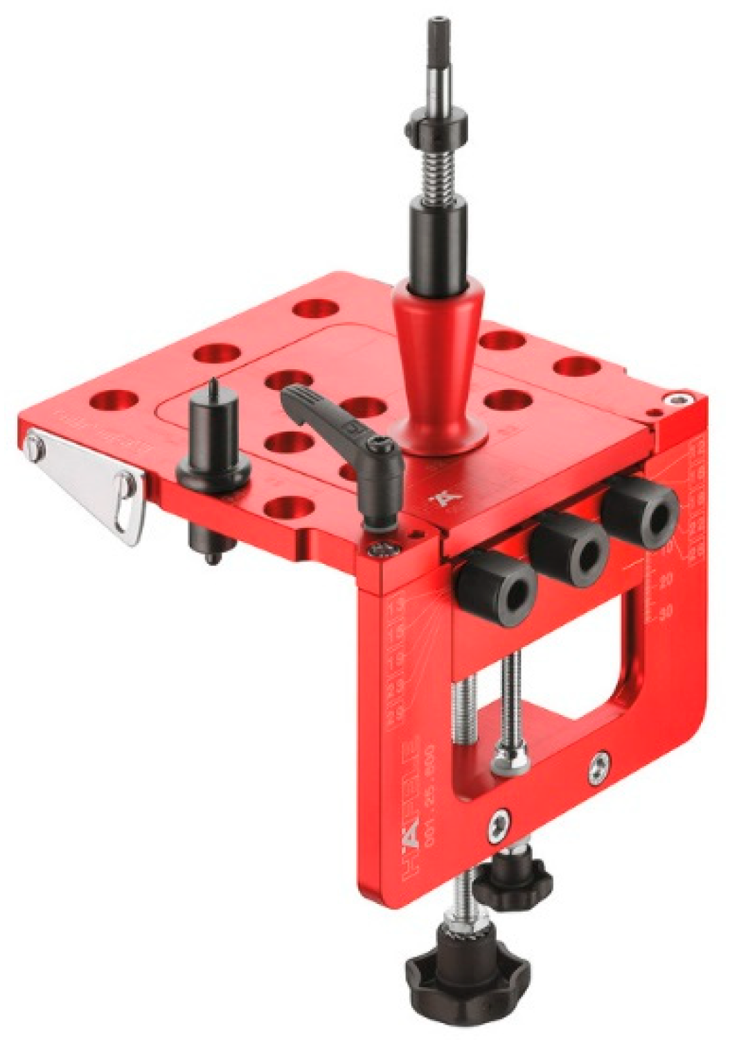
2.2. Sample Preparation

| Specimen’s Type | Parts Used in Joint Connection | Number of Fittings in the Joint Connection |
|---|---|---|
| A |  | • 2 pcs Clamex P-14 (Lamello©—145334) |
| B | 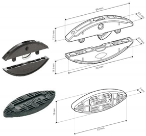 | • 2 pcs Clamex P-14 (Lamello©—145334) • 1 pcs Bisco-P15 (Lamello©—145304) |
| C | 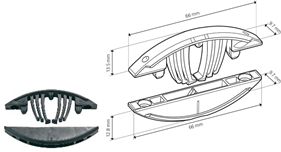 | • 2 pcs Tenso P-14 (Lamello©—145415) |
| D |  | • 2 pcs steel bolt S100 (262.28.026) • 2 pcs Minifix® 15 (262.26.034) • 2 pcs beach dowel (262.82.235) |
| E |  | • 2 pcs steel bolts S100 M4 (262.28.937) • 2 pcs Minifix® 15 (262.26.034) • 2 pcs insert nut M4 (051.45.004) • 2 pcs beach dowel (262.82.235) |
| F | 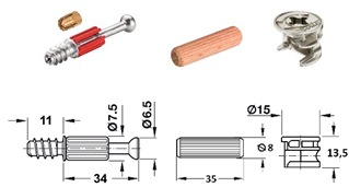 | • 2 pcs steel bolt S200 (262.28.670) • 2 pcs Minifix® 15 (262.26.034) • 2 pcs beach dowel (262.82.235) |
| G | 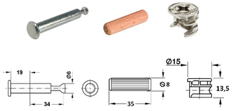 | • 2 pcs capped bolt (262.28.765) • 2 pcs Minifix® 15 (262.26.034) • 2 pcs beach dowel (262.82.235) |
2.3. Method of Testing
3. Results and Discussion
3.1. Results of Mechanical Testing
3.2. Discussion
4. Conclusions
Author Contributions
Funding
Institutional Review Board Statement
Informed Consent Statement
Data Availability Statement
Conflicts of Interest
References
- Janíková, N.; Šimek, M.; Kořený, A.; Gaff, M.; Hlavatý, J. Comparing furniture joint variants using a multi-criteria analysis. Wood Mater. Sci. Eng. 2025, 1–10. [Google Scholar] [CrossRef]
- Karaman, A. The Effect of Fastener Type (Clamex P14 and Tenso P14) and Adhesive Type on Diagonal Compression and Diagonal Tension Performance. Bartın Orman. Fak. Derg. 2020, 22, 144–152. [Google Scholar] [CrossRef]
- Karaman, A. An investigation on the effect of wood species of dowels and the end distance of catch connectors (Clamex P-14) on the bending moment of L-type corner joints for RTA (ready-to-assemble) furnitures. For. Prod. Program. 2021, 53, 48–61. [Google Scholar] [CrossRef]
- Silvana, P.; Jankovic, L.; Brezovic, M. Design Analysis of Showcase with Console Shelves. In Conference Research for Furniture Industry; Available online: https://www.researchgate.net/publication/337716410_DESIGN_ANALYSIS_OF_SHOWCASE_CABINET_WITH_CONSOLE_SHELVES (accessed on 29 April 2025).
- Sydor, M.; Pohl, P. Load-bearing capacity and characteristic forms of destruction of furniture joints made with rastex 15 and P-10 clamex fasteners. Ann. WULS For. Wood Technol. 2019, 106, 38–48. [Google Scholar] [CrossRef]
- Karaman, A. Determination of Bending Moment Capacity on “L” Type Furniture Corner Assembly Elements Produced by 3D Printers. Gümüşhane Üniv. Fen. Bilim. Enst. Derg. 2020, 10, 1057–1065. [Google Scholar] [CrossRef]
- Atar, M.; Ozcifci, A.; Altinok, M.; Celikel, U. Determination of diagonal compression and tension performances for case furniture corner joints constructed with wood biscuits. Mater. Des. 2009, 30, 665–670. [Google Scholar] [CrossRef]
- Tankut, A.N.; Tankut, N. Effect of some factors on the strength of furniture corner joints constructed with wood biscuits. Turk. J. Agric. For. 2004, 28, 301–309. [Google Scholar]
- Atar, M.; Gode, F.; Kucuktuvek, M.; Akan, A.E.; Ormecioglu, H.T.; Keskin, H. Tensile Performance of Traditional and Modern Corner Joints in Wooden Structures. Drv. Ind. 2022, 73, 69–80. [Google Scholar] [CrossRef]
- Zhang, K.; Zhang, J.; Guo, Y.; Chen, Y. Study on Joint Model Simplification for Finite Element Analysis of Bamboo/Wood-Oriented Strand Board Furniture. Materials 2024, 17, 4395. [Google Scholar] [CrossRef]
- Kureli, I.; Altinok, M. Determination of mechanical performances of the portable fasteners used on case furniture joints. Afr. J. Agric. Res. 2011, 6, 4893–4901. [Google Scholar]
- Šimek, M.; Konas, P. Bending stress modeling of demountable furniture joints applied with a use of finite element method. Acta Univ. Agric. Et Silvic. Mendel. Brun. 2009, 57, 137–146. [Google Scholar] [CrossRef]
- Janíková, N.; Šimek, M.; Kořený, A.; Gaff, M.; Hlavatý, J. Comparative study on the bending moment capacity and stiffness of innovative and traditional furniture corner joints. Wood Mater. Sci. Eng. 2024. [Google Scholar] [CrossRef]
- Krzyżaniak, L.; Smardzewski, J. Impact damage response of L-type corner joints connected with new innovative furniture fasteners in wood-based composites panels. Compos. Struct. 2020, 255, 113008. [Google Scholar] [CrossRef]
- Smardzewski, J.; Lewandowski, W.; İmirzi, H.Ö. Elasticity modulus of cabinet furniture joints. Mater. Des. 2014, 60, 260–266. [Google Scholar] [CrossRef]
- Guo, Y.; Qin, W.; Chen, Y.; Liu, S.; Zhu, S.; Cao, C.; Zhu, Z. Moment capacity of furniture corner joints made from Bamboo-oriented strand board. Wood Fiber Sci. J. Soc. Wood Sci. Technol. 2019, 51, 255–263. [Google Scholar] [CrossRef]
- Kucuktuvek, M.; Kasal, A.; Kuşkun, T.; Erdil, Y.Z. Utilizing Poppy Husk-Based Particleboards as an Alternative Material in Case Furniture Construction. BioResources 2017, 12, 839–852. [Google Scholar] [CrossRef]
- Hu, W.; Zhao, Y.; Xu, W.; Liu, Y. Study on withdrawal force capacity of insert nut in wood-based materials used for case furniture. Wood Mater. Sci. Eng. 2024, 1–10. [Google Scholar] [CrossRef]
- Hu, W.; Zhao, Y.; Xu, W.; Liu, Y. The Influences of Selected Factors on Bending Moment Capacity of Case Furniture Joints. Appl. Sci. 2024, 14, 10044. [Google Scholar] [CrossRef]
- Yerlikaya, N.C. Effects of glass–fiber composite, dowel, and minifix fasteners on the failure load of corner joints in particleboard case-type furniture. Mater. Des. 2012, 39, 63–71. [Google Scholar] [CrossRef]
- Skorupinska, E.; Wiaderek, K.; Sydor, M. Withdrawal Resistance of T-Nuts in Various Furniture Materials. Drv. Ind. 2022, 73, 271–277. [Google Scholar] [CrossRef]
- Jivkov, V. Influence of Edge Banding on Banding Strength of End Corner Joints from 18 mm Particleboard; Technical University Zvolen: Zvolen, Slovakia, 2002. [Google Scholar]
- Jivkov, V.; Simeonova, R.; Antov, P.; Marinova, A.; Petrova, B.; Kristak, L. Structural Application of Lightweight Panels Made of Waste Cardboard and Beech Veneer. Materials 2014, 14, 5064. [Google Scholar] [CrossRef]
- Karaman, A. The effects of wooden dowel species and the end distance of minifix fastener on the shear force capacity for H-type furniture joints. Wood Fiber Sci. 2024, 56, 1–8. [Google Scholar]
- Klos, R.; Langová, N. Determination of Reliability of Selected Case Furniture Constructions. Appl. Sci. 2023, 13, 4587. [Google Scholar] [CrossRef]
- Máchová, E.; Langová, N.; Réh, R.; Joščák, P.; Krišťák, Ľ.; Holouš, Z.; Igaz, R.; Hitka, M. Effect of Moisture Content on the Load Carrying Capacity and Stiffness of Corner Wood-Based and Plastic Joints. BioResources 2019, 14, 8640–8655. [Google Scholar] [CrossRef]
- Klos, R.; Fabisiak, B.; Ng, H.K.T. Comparative reliability analysis of selected joints for case furniture. BioRecources 2018, 13, 5111–5123. [Google Scholar] [CrossRef]
- Kasal, A.; Erdil, Y.Z.; Zhang, J.; Efe, H.; Avci, E. Estimation equations for moment resistances of L-type screw corner joints in case goods furniture. For. Prod. J. 2008, 58. [Google Scholar]
- Kasal, A.; Şener, S.; Belgin, Ç.; Efe, H. Bending Strength of Screwed Corner Joints with Different Materials. Gazi Univ. J. Sci. 2010, 19, 155–161. [Google Scholar]
- Bas, S.; Denes, L.; Csiha, C. Mechanical Properties of Furniture Joints Using Loose Tenons and Connectors. Forests 2024, 15, 343. [Google Scholar] [CrossRef]
- Smietanska, K.; Mielczarek, M. Strength properties of furniture corner joints constructed with different wooden connectors and wood-based materials. Ann. WULS For. Wood Technol. 2022, 118, 55–66. [Google Scholar] [CrossRef]
- Kasal, A.; Kuşkun, T.; Smardzewski, J. Experimental and Numerical Study on Withdrawal Strength of Different Types of Auxetic Dowels for Furniture Joints. Materials 2020, 13, 4252. [Google Scholar] [CrossRef]
- Kasal, A.; Smardzewski, J.; Kuşkun, T.; Güray, E. Analyses of L-Type Corner Joints Connected with Auxetic Dowels for Case Furniture. Materials 2023, 16, 4547. [Google Scholar] [CrossRef] [PubMed]
- Kuskun, N.; Smardzewski, J.; Kasal, A. Experimental and numerical analysis of mounting force of auxetic dowels for furniture joints. Eng. Struct. 2020, 226, 111351. [Google Scholar] [CrossRef]
- Kuskun, N.; Kasal, A.; Çağlayan, G.; Ceylan, E.; Bulca, M.; Smardzewski, J. Optimization of the Cross-Sectional Geometry of Auxetic Dowels for Furniture Joints. Materials 2023, 16, 2838. [Google Scholar] [CrossRef]
- Smardzewski, J.; Rzepa, B.; Kıliç, H. Mechanical Properties of Externally Invisible Furniture Joints Made of Wood-Based Composite. BioResources 2016, 11, 1224–1239. [Google Scholar] [CrossRef]
- Branowski, B.; Starczewski, K.; Zabłocki, M.; Sydor, M. Design issues of innovative furniture fasteners for wood-based boards. BioResources 2020, 15, 8472–8495. [Google Scholar] [CrossRef]
- Petrova, B.; Jivkov, V. Application of 3D Printing Technology in Furniture Construction. Materials 2024, 17, 4848. [Google Scholar] [CrossRef]
- Sydor, M.; Kwapich, A.; Pohl, P. Strength comparative analysis of furniture joints made of various materials. Ann. WULS For. Wood Technol. 2021, 113, 89–97. [Google Scholar] [CrossRef]

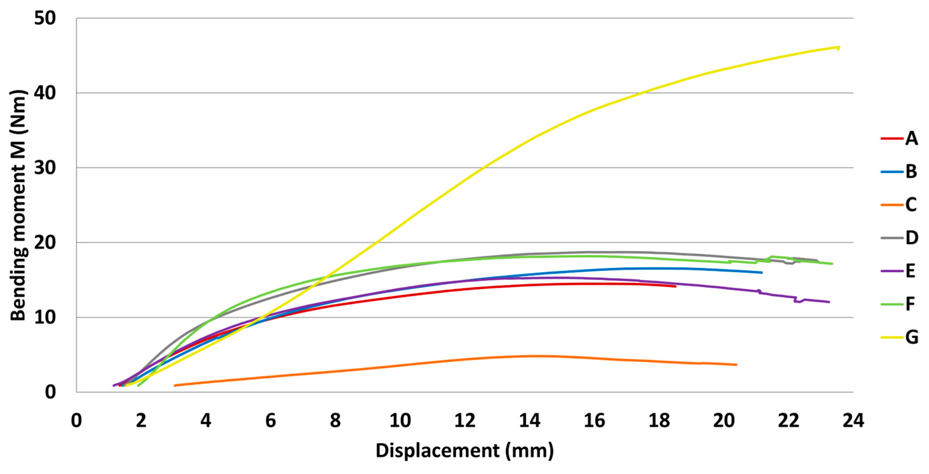

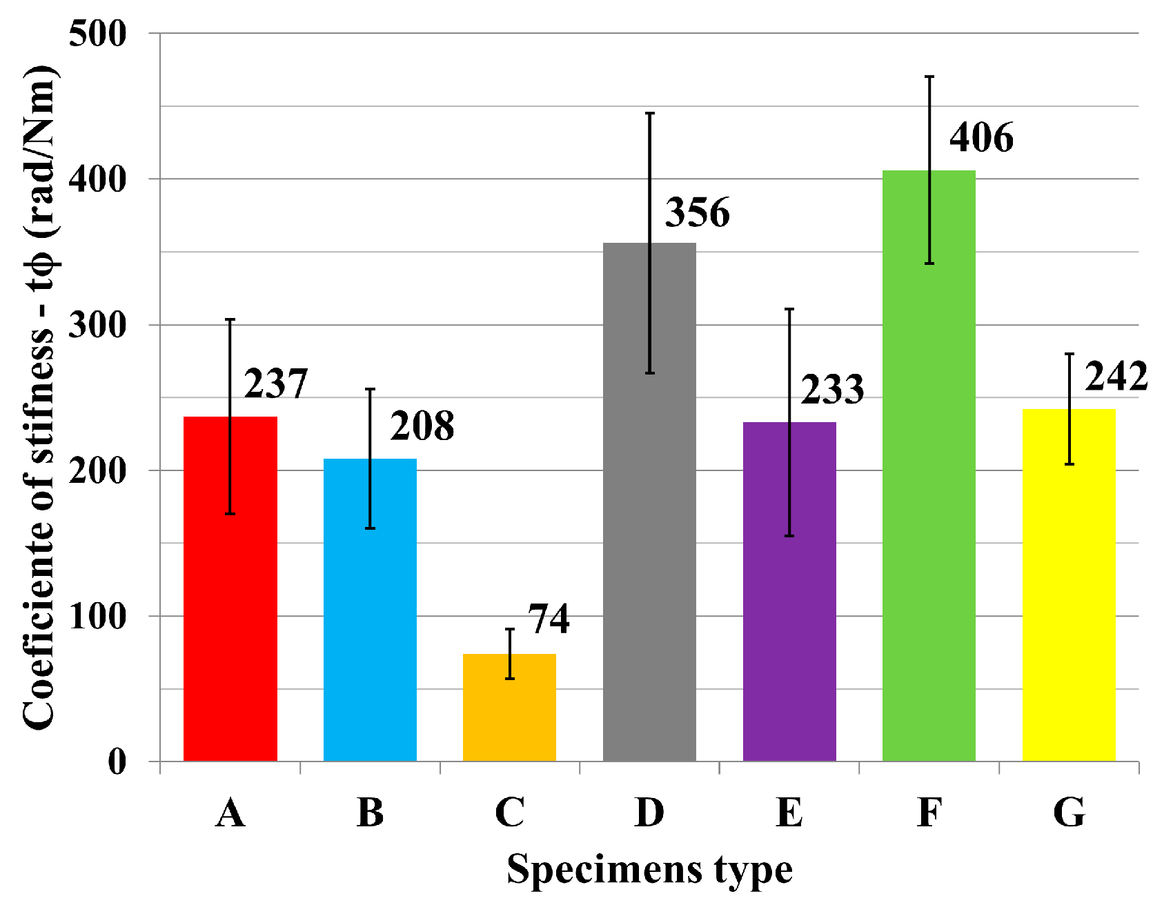


| Specimen Type | N | Mean (Nm) | Stiffness (Nm/rad) | Variance (%) |
|---|---|---|---|---|
| A | 10 | 15 | 237 | 8.78 |
| B | 10 | 17 | 208 | 1.44 |
| C | 10 | 5 | 74 | 0.12 |
| D | 10 | 19 | 356 | 4.53 |
| E | 10 | 15 | 233 | 5.02 |
| F | 9 | 18 | 406 | 2.58 |
| G | 10 | 47 | 242 | 3.84 |
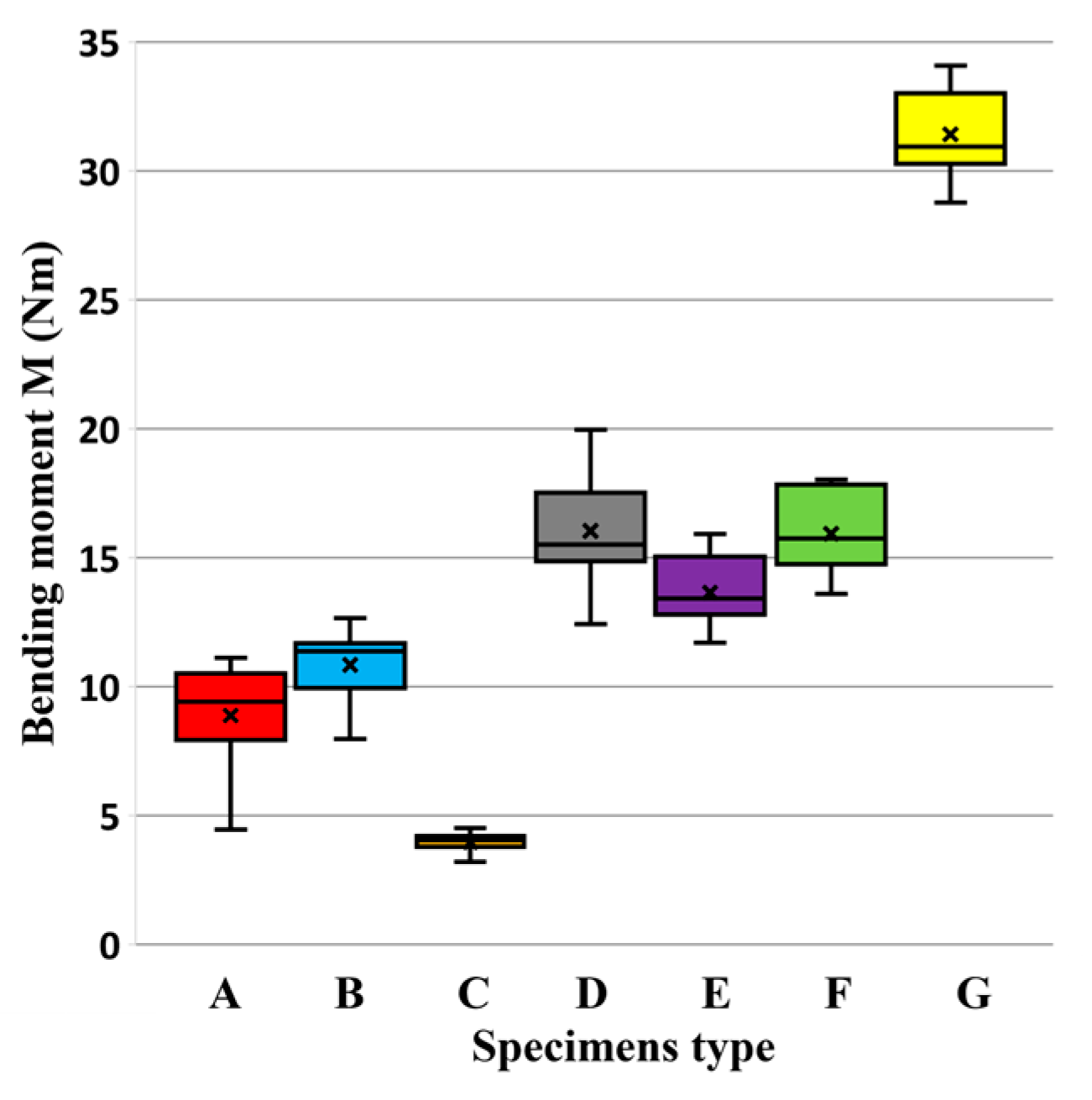
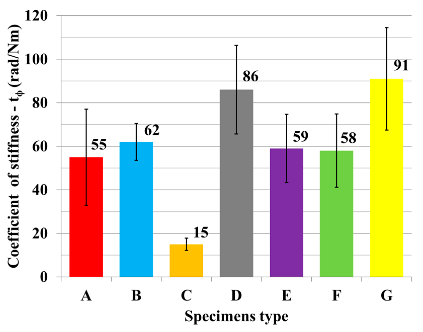
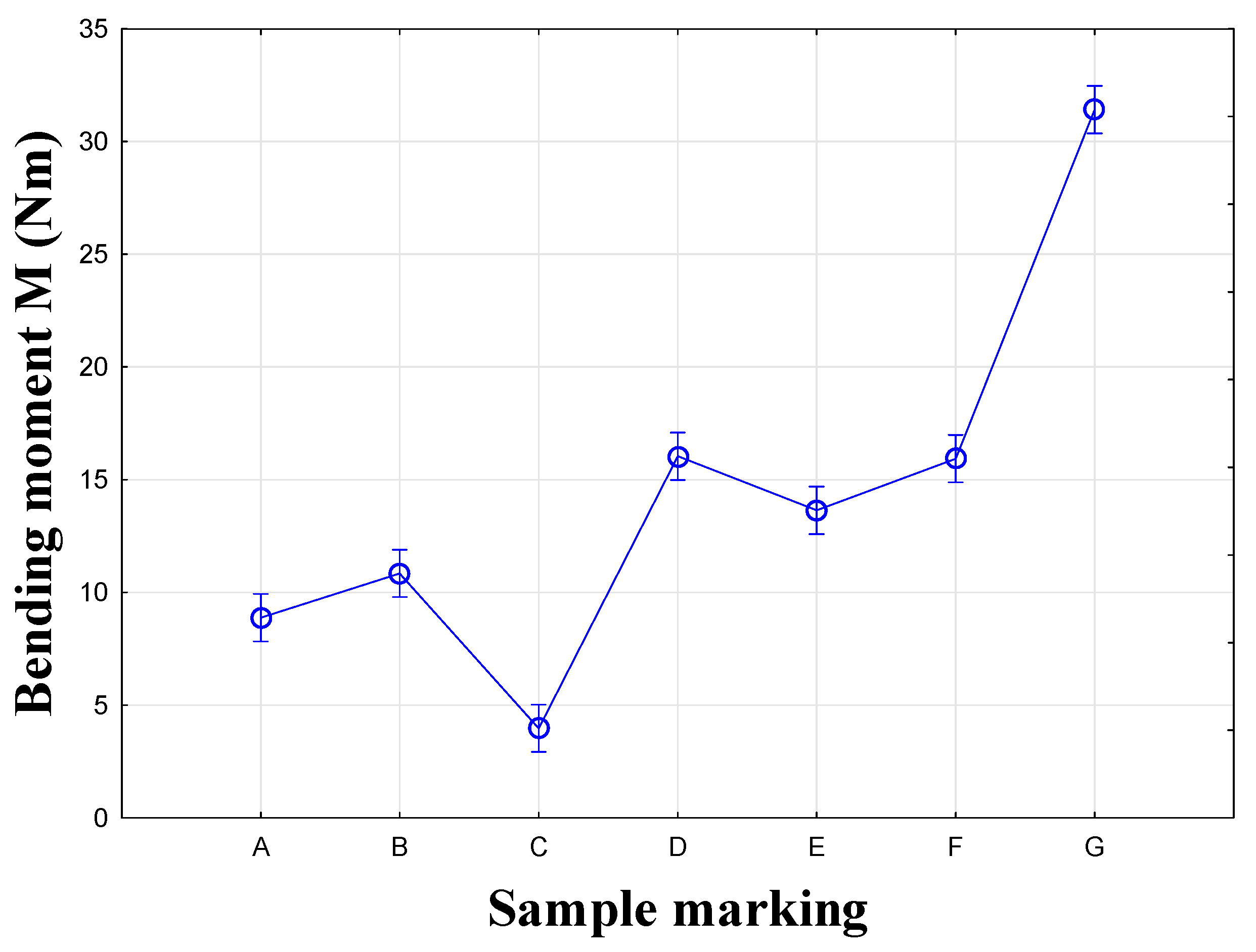
| Specimen Type | N | Mean (Nm) | Stiffness (Nm/rad) | Variance (%) |
|---|---|---|---|---|
| A | 10 | 9 | 55 | 4.19 |
| B | 10 | 11 | 62 | 2.31 |
| C | 10 | 4 | 15 | 0.15 |
| D | 10 | 16 | 86 | 5.57 |
| E | 10 | 14 | 59 | 1.75 |
| F | 10 | 16 | 58 | 2.51 |
| G | 10 | 31 | 91 | 2.82 |
| Source of Variance | Sum of Squares | Degrees of Freedom | Mean Squares | F-Value | p-Value | F-Critical |
|---|---|---|---|---|---|---|
| Between groups | 10,067.12 | 6 | 1677.858 | 444.23 | 5.74 | 2.25 |
| Within groups | 234.17 | 62 | 3.78 | |||
| Total | 10,301.3 | 68 |
| Source of Variance | Sum of Squares | Degrees of Freedom | Mean Squares | F-Value | p-Value | F-Critical |
|---|---|---|---|---|---|---|
| Sample | 8794.79 | 6 | 1465.79 | 352.97 | 3.02 × 10−76 | 2.17 |
| Columns | 604.54 | 1 | 604.54 | 145.57 | 9.37 × 10⁻²³ | 3.91 |
| Interaction | 2415.42 | 6 | 402.57 | 96.94 | 8.63 × 10−45 | 2.17 |
| Within | 523.25 | 126 | 4.15 | |||
| Total | 12,338.01 | 139 |
| Specimen Type | Mean (M/Nm) | Homogeneity Groups | |||
|---|---|---|---|---|---|
| 1 | 2 | 3 | 4 | ||
| C | 5 | *** | |||
| A | 15 | *** | |||
| E | 15 | *** | |||
| B | 17 | *** | *** | ||
| F | 18 | *** | |||
| D | 19 | *** | |||
| G | 47 | *** | |||
| Source of Variance | Sum of Squares | Degrees of Freedom | Mean Squares | F-Value | p-Value | F-Critical |
|---|---|---|---|---|---|---|
| Between groups | 4469.03 | 6 | 744.84 | 270.21 | 5.64 | 2.25 |
| Within groups | 173.66 | 63 | 2.76 | |||
| Total | 4642.69 | 69 |
| Source of Variance | Sum of Squares | Degrees of Freedom | Mean Squares | F-Value | p-Value | F-Critical |
|---|---|---|---|---|---|---|
| Sample | 3302.88 | 6 | 550.48 | 188.88 | 1.75 × 10−60 | 2.17 |
| Columns | 1041.82 | 1 | 1041.82 | 357.47 | 1.33 × 10−38 | 3.91 |
| Interaction | 1470.23 | 6 | 245.04 | 84.078 | 1.18 × 10−41 | 2.17 |
| Within | 367.21 | 126 | 2.91 | |||
| Total | 6182.15 | 139 |
| Specimen Type | Mean (M/Nm) | Homogeneity Groups | ||||
|---|---|---|---|---|---|---|
| 1 | 2 | 3 | 4 | 5 | ||
| C | 4 | *** | ||||
| A | 9 | *** | ||||
| B | 11 | *** | ||||
| E | 14 | *** | ||||
| F | 16 | *** | ||||
| D | 16 | *** | ||||
| G | 31 | *** | ||||
Disclaimer/Publisher’s Note: The statements, opinions and data contained in all publications are solely those of the individual author(s) and contributor(s) and not of MDPI and/or the editor(s). MDPI and/or the editor(s) disclaim responsibility for any injury to people or property resulting from any ideas, methods, instructions or products referred to in the content. |
© 2025 by the authors. Licensee MDPI, Basel, Switzerland. This article is an open access article distributed under the terms and conditions of the Creative Commons Attribution (CC BY) license (https://creativecommons.org/licenses/by/4.0/).
Share and Cite
Janíková, N.; Kořený, A.; Gaff, M.; Hlavatý, J. Comparative Study on Strengths of Ready-to-Assemble and Eccentric Furniture Joint. Materials 2025, 18, 2114. https://doi.org/10.3390/ma18092114
Janíková N, Kořený A, Gaff M, Hlavatý J. Comparative Study on Strengths of Ready-to-Assemble and Eccentric Furniture Joint. Materials. 2025; 18(9):2114. https://doi.org/10.3390/ma18092114
Chicago/Turabian StyleJaníková, Nikola, Adam Kořený, Milan Gaff, and Josef Hlavatý. 2025. "Comparative Study on Strengths of Ready-to-Assemble and Eccentric Furniture Joint" Materials 18, no. 9: 2114. https://doi.org/10.3390/ma18092114
APA StyleJaníková, N., Kořený, A., Gaff, M., & Hlavatý, J. (2025). Comparative Study on Strengths of Ready-to-Assemble and Eccentric Furniture Joint. Materials, 18(9), 2114. https://doi.org/10.3390/ma18092114