
The Influence of the Annular Nozzle’s Structural Parameters on Powder Stream Convergence for Laser-Directed Energy Deposition


Abstract
1. Introduction
2. Finite Element Model of the Structure of the L-DED Powder Feeding Nozzle
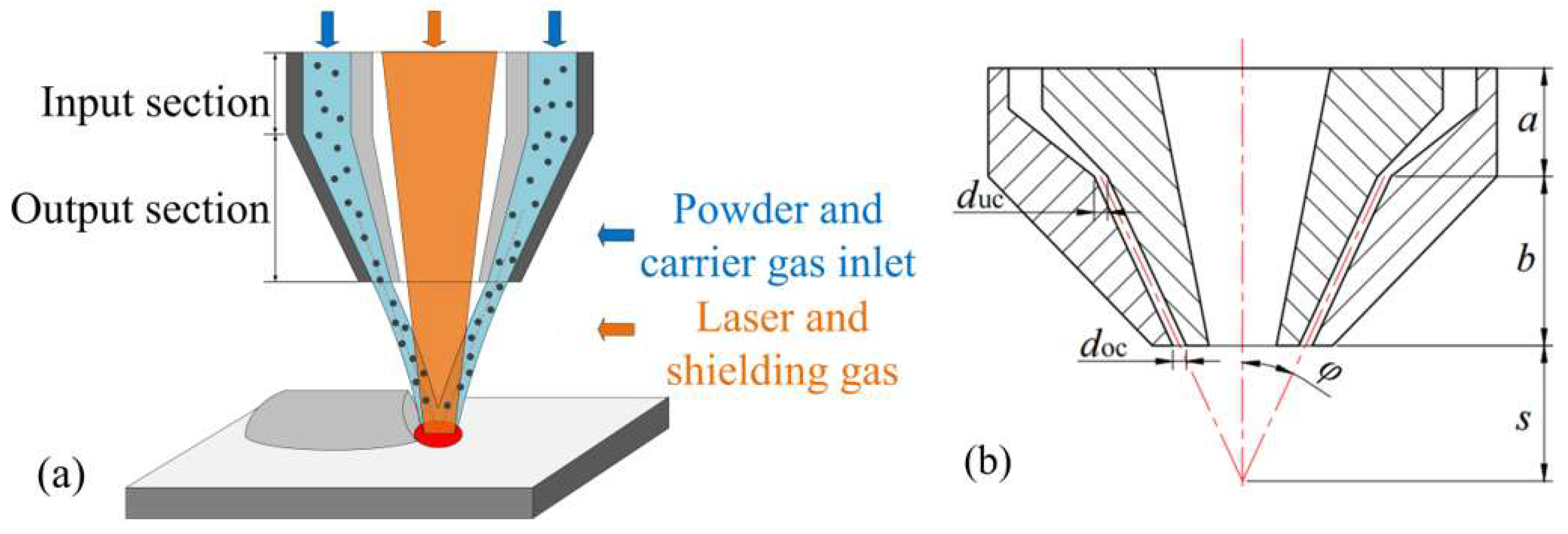
2.1. Annular Nozzle Geometry
2.2. Simulation Model and Theory
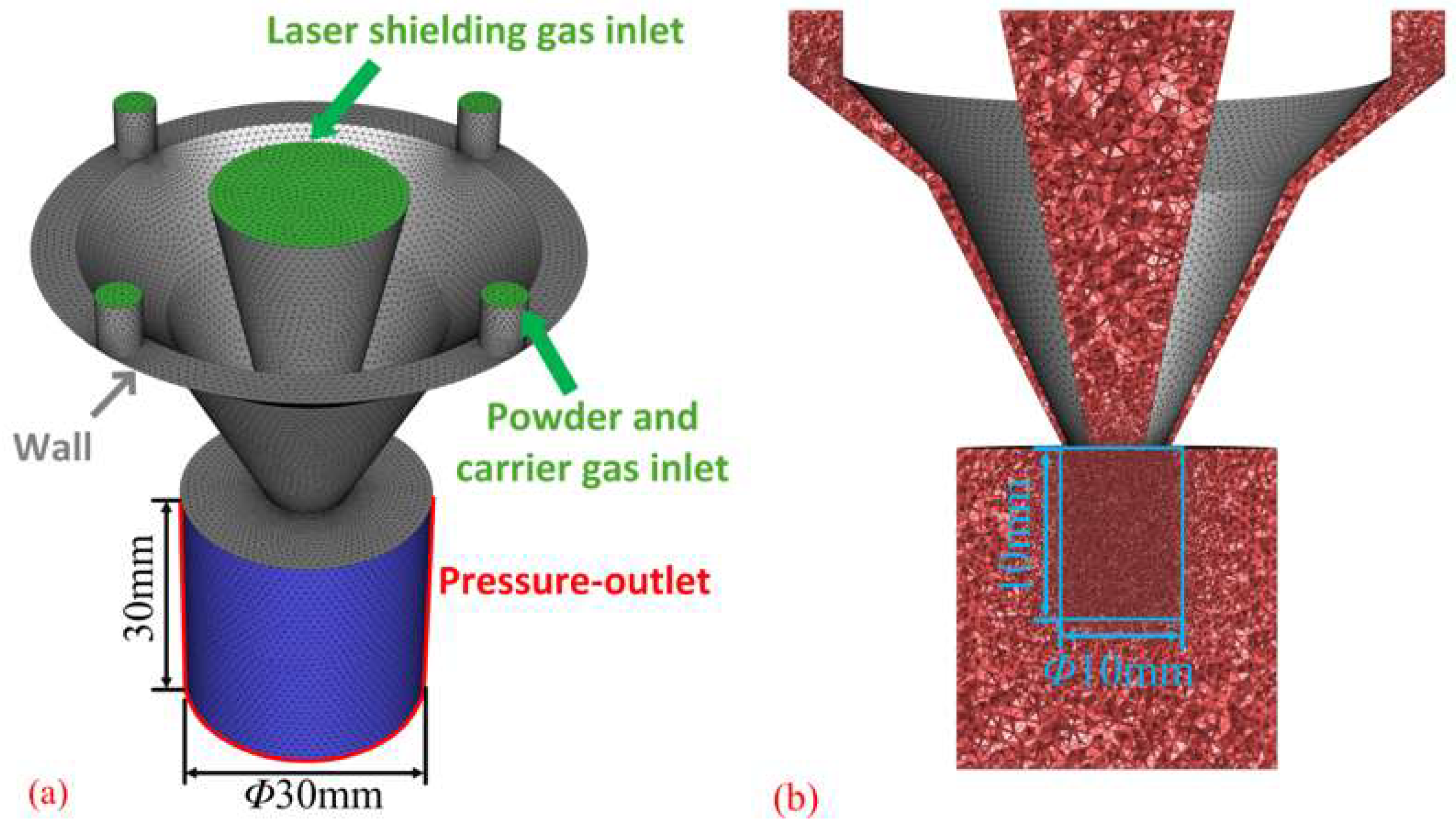
2.2.1. Simulation Model
- In the calculation of the simulated powder feeding process, the influence of heat transfer between other heat sources such as laser radiation and the powder particles is not considered, so only the drag force, inertial force, and gravity of the discrete phase are considered, and other forces are ignored.
- The simulation calculation adopts transient flow analysis, and the time step size is 0.001 s, the number of time steps is 1000, and the convergence accuracy is 10−3.
- Ignoring the bouncing of particles on the substrate, the particle flow is assumed to be a free jet.
- The gas used is argon. Table 2 shows the specific parameters.
- The powder particles are spherical, and their particle size distribution adopts the Rosin–Rammler particle size distribution method, and the specific parameters are shown in Table 3.
2.2.2. Continuous Phase Governing Equation
2.2.3. Discrete Phase Governing Equation
3. Experimental Verification
4. Results and Discussion
4.1. Effect of Nozzle Structure on Powder Convergence
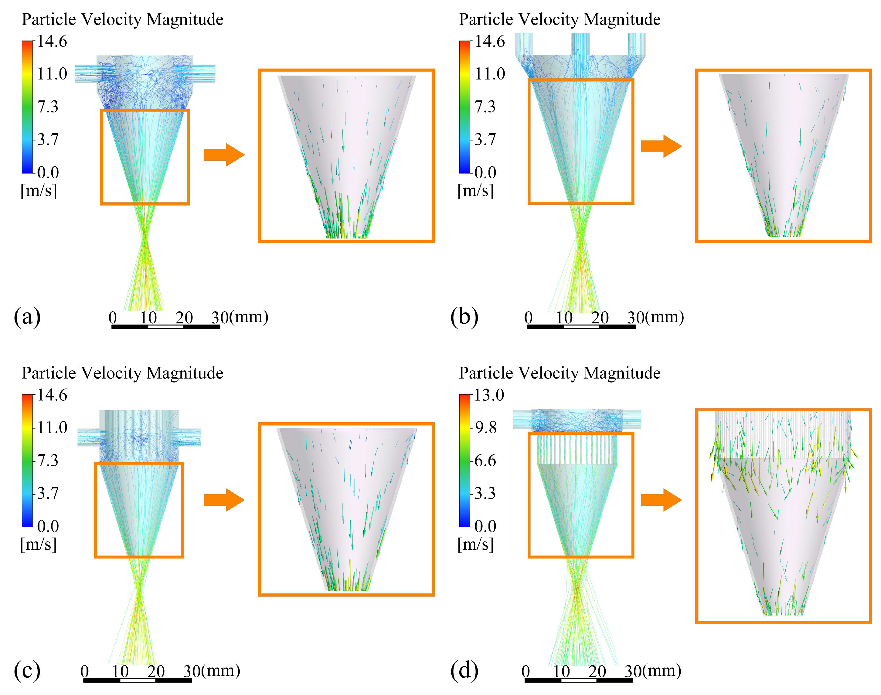
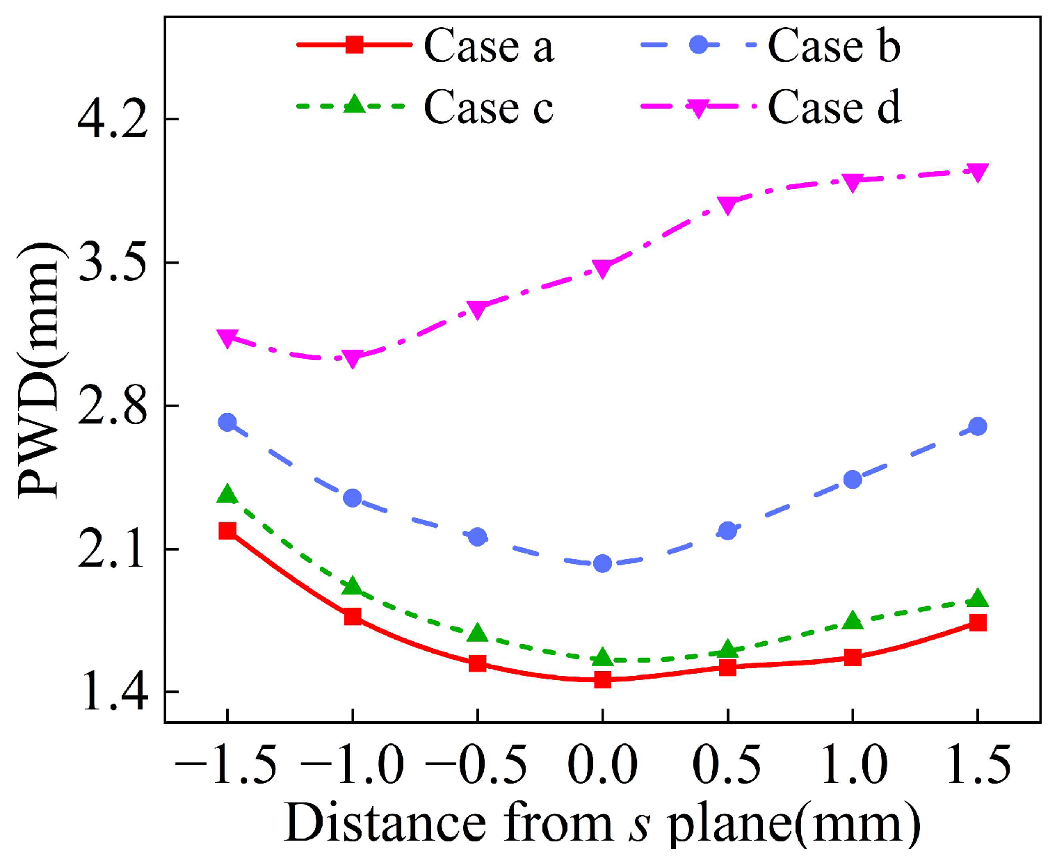
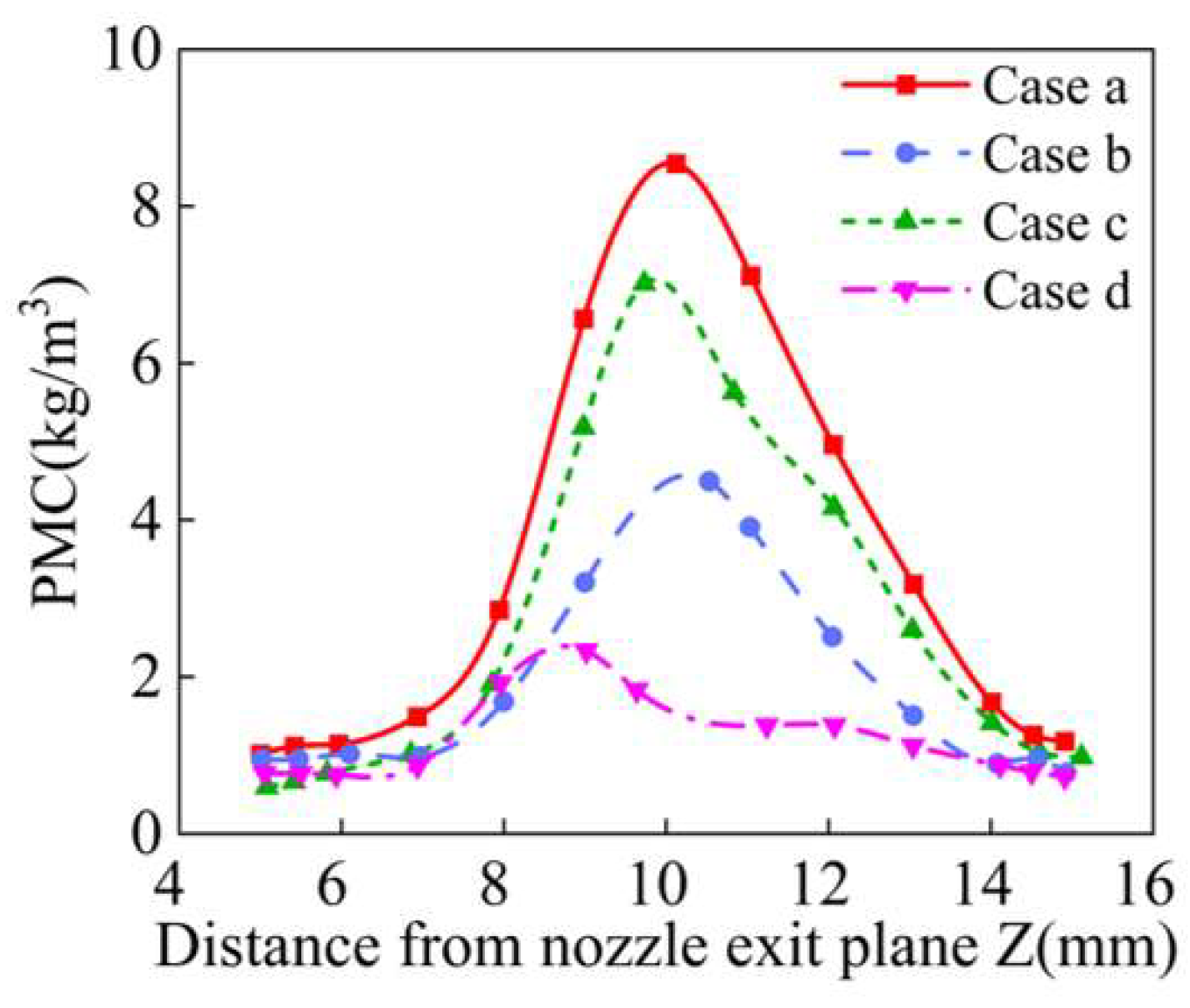
4.1.1. Outlet Shape
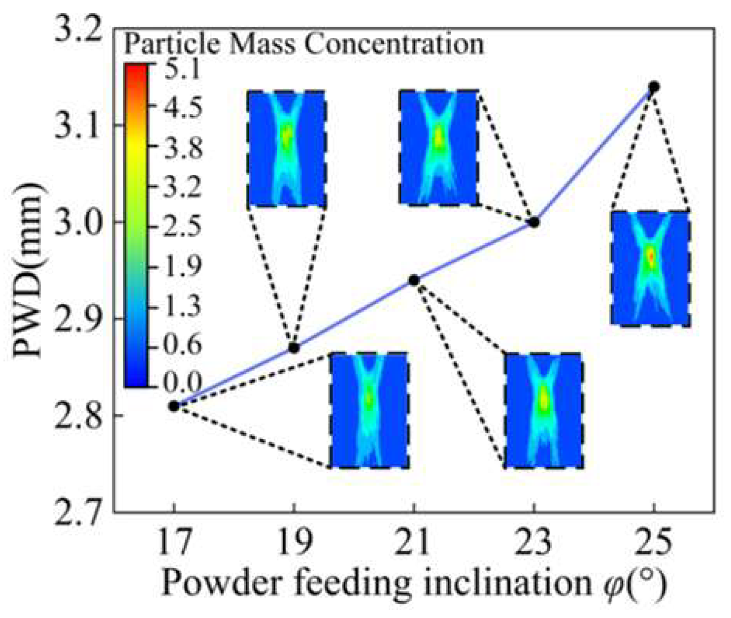
4.1.2. Feeding Inclination Angle
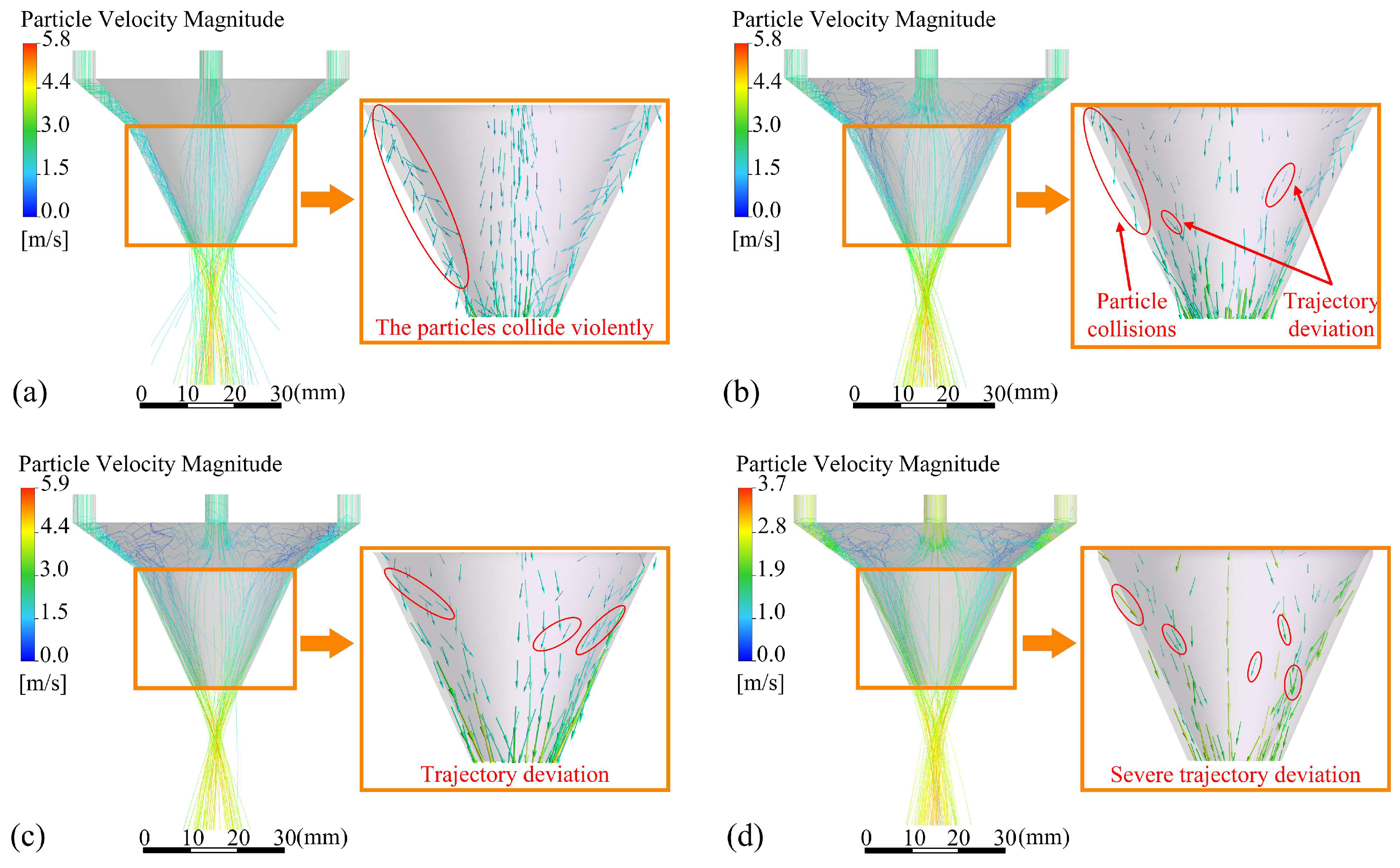
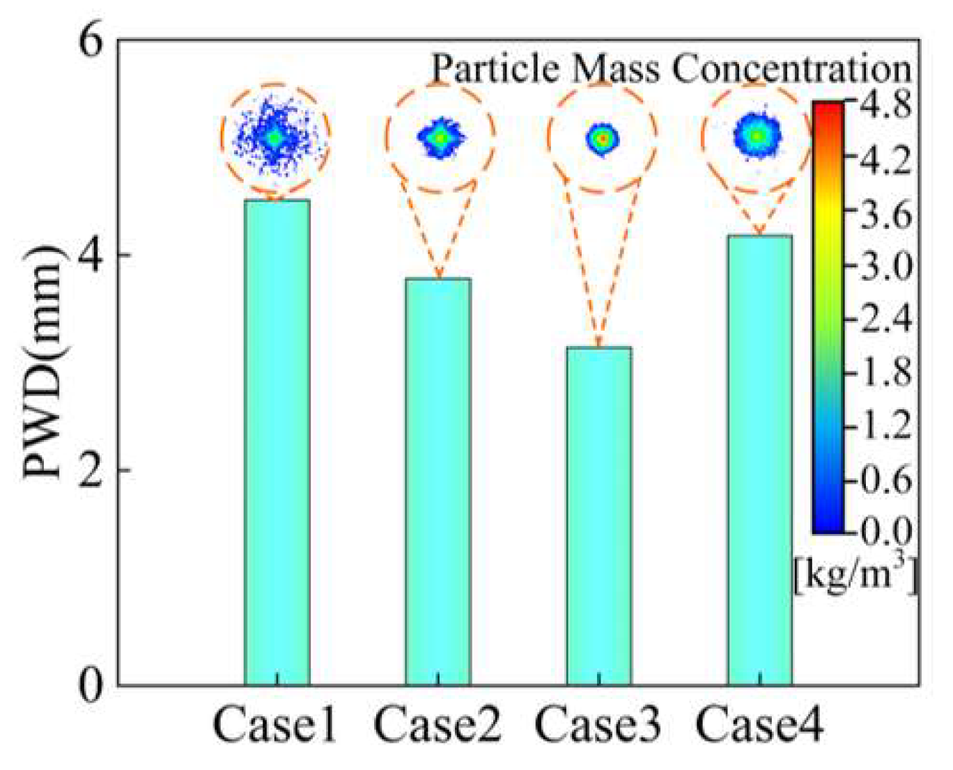
4.1.3. Outlet Gap
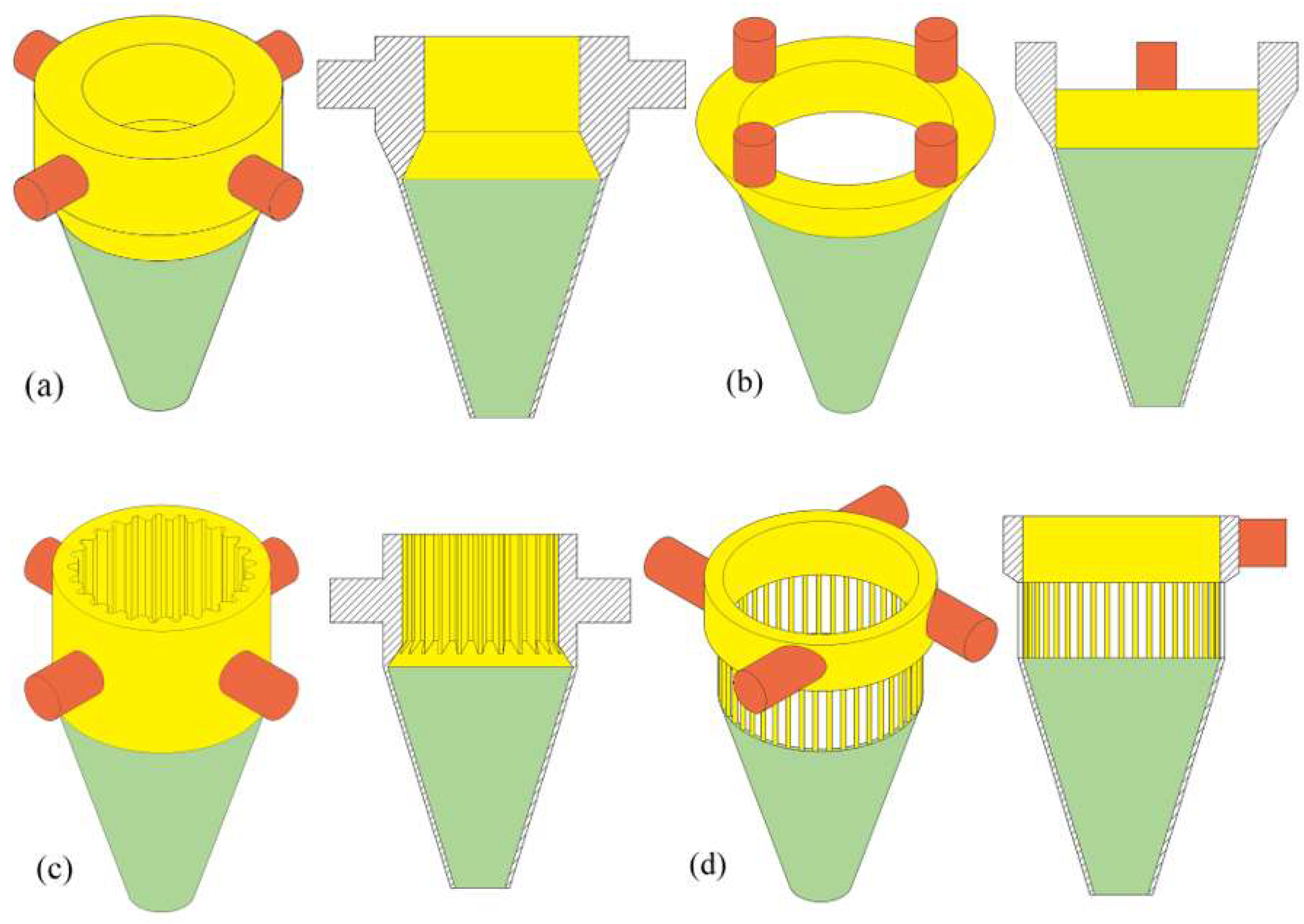
4.1.4. Inlet Shape
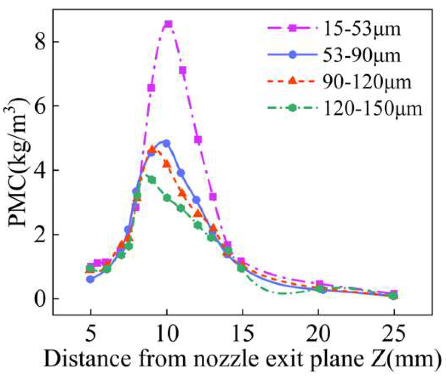
4.2. Effect of Particle Size on Powder Convergence
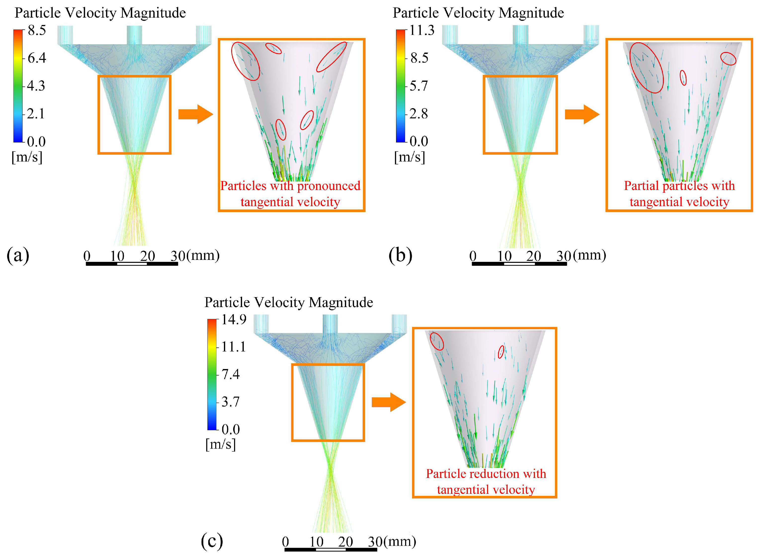
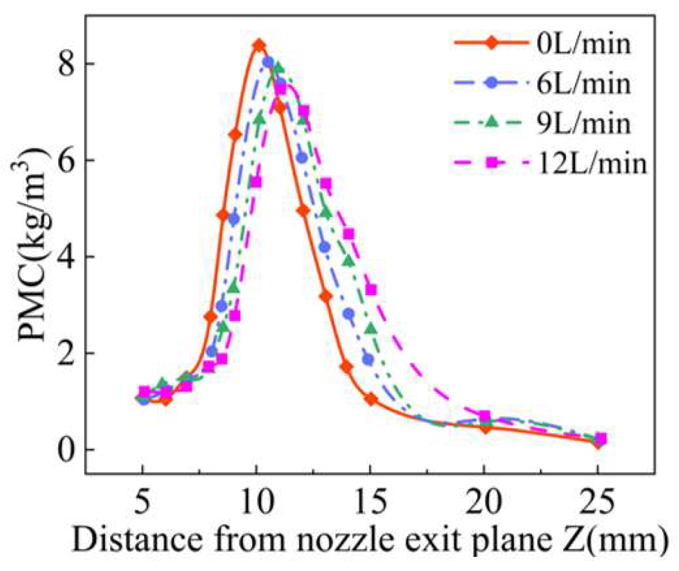
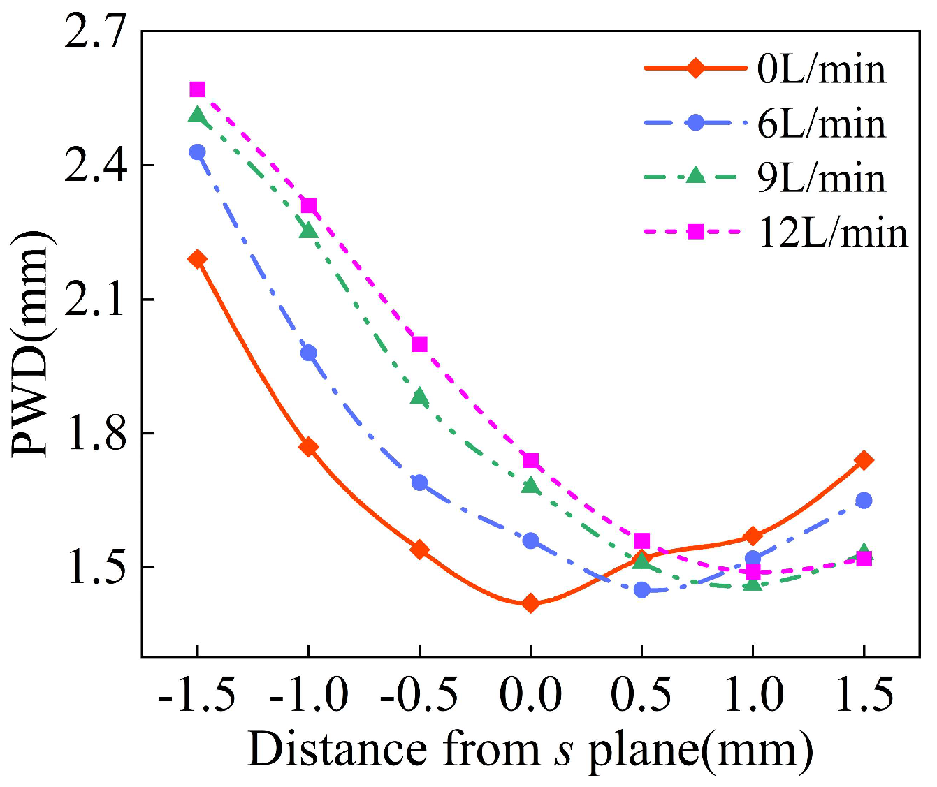
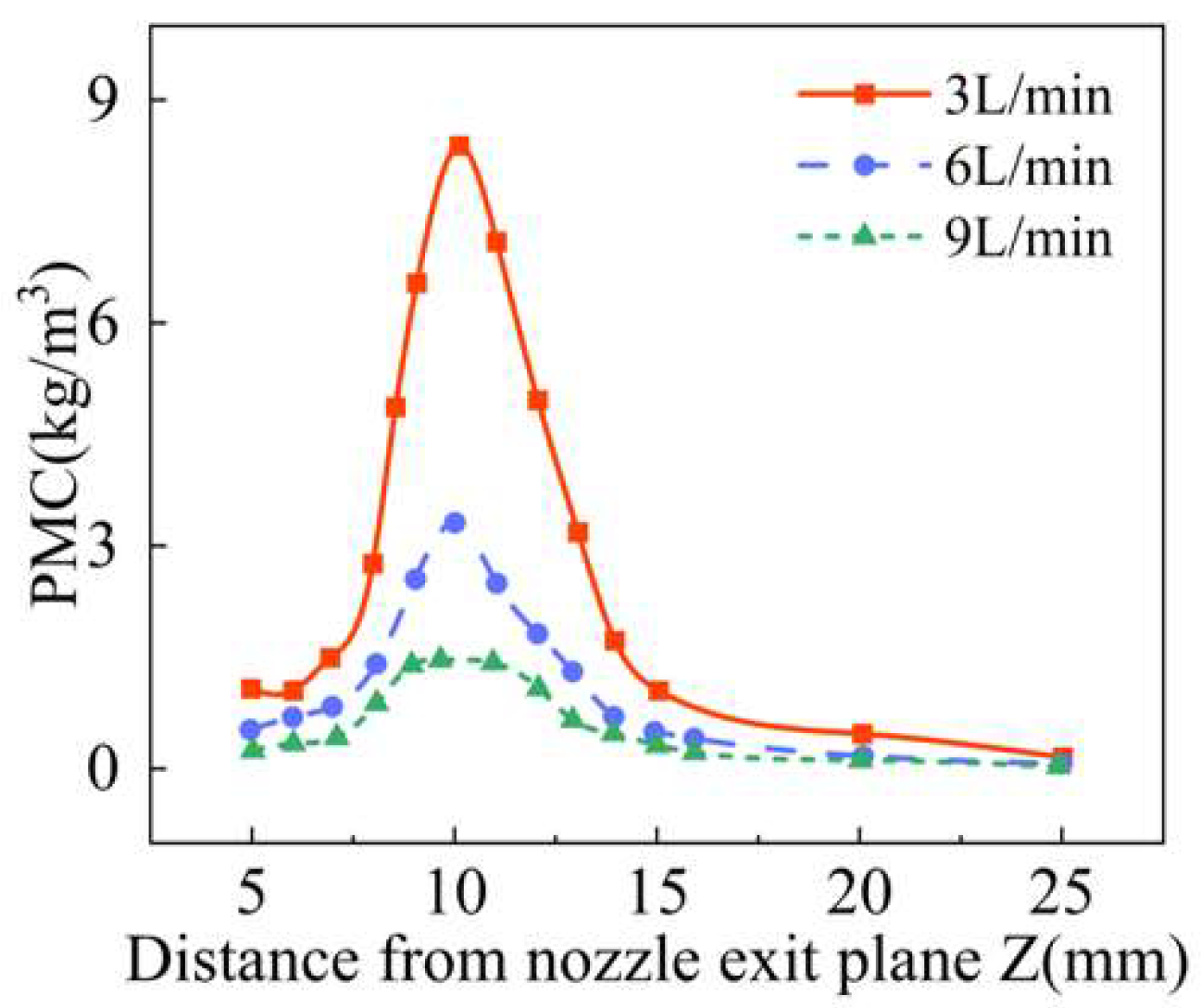
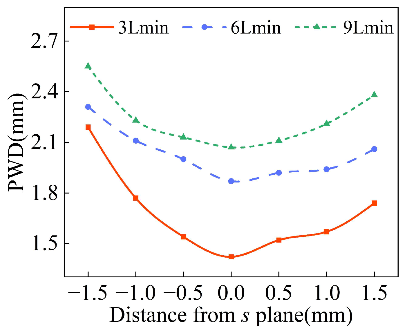
4.3. Effect of Gas Rate on Powder Convergence
5. Conclusions
Author Contributions
Funding
Institutional Review Board Statement
Informed Consent Statement
Data Availability Statement
Conflicts of Interest
References
- Zhang, T.L.; Liu, C.T. Design of titanium alloys by additive manufacturing: A critical review. Adv. Powder Mater. 2022, 1, 100014. [Google Scholar] [CrossRef]
- Li, B.B.; Gao, E.Z.; Yin, J.; Li, X.D.; Yang, G.; Liu, Q. Research on the Deformation Prediction Method for the Laser Deposition Manufacturing of Metal Components Based on Feature Partitioning and the Inherent Strain Method. Mathematics 2024, 12, 898. [Google Scholar] [CrossRef]
- Li, B.B.; Zhang, J.; Yin, J.; Gao, E.Y.; Yang, G. Distortion prediction method for large-scale additive metal components based on feature partitioning and temperature function method. Int. J. Adv. Manuf. Technol. 2024, 130, 1373–1391. [Google Scholar] [CrossRef]
- Kahhal, P.; Jo, Y.K.; Park, S.H. Recent progress in remanufacturing technologies using metal additive manufacturing processes and surface treatment. Int. J. Pr. Eng. Man.-Green Technol. 2024, 11, 625–658. [Google Scholar] [CrossRef]
- Svetlizky, D.; Das, M.; Zheng, B.; Vyatskikh, A.L.; Bose, S.; Bandyopadhyay, A.; Schoenung, J.M.; Lavernia, E.J.; Eliaz, N. Directed energy deposition (DED) additive manufacturing: Physical characteristics, defects, challenges and applications. Mater. Today 2021, 49, 271–295. [Google Scholar] [CrossRef]
- Kanishka, K.; Acherjee, B. A systematic review of additive manufacturing-based remanufacturing techniques for component repair and restoration. J. Manuf. Process. 2023, 89, 220–283. [Google Scholar] [CrossRef]
- Aprilia, A.; Wu, N.; Zhou, W. Repair and restoration of engineering components by laser directed energy deposition. Mater. Today Proc. 2022, 70, 206–211. [Google Scholar] [CrossRef]
- Hamilton, J.D.; Sorondo, S.; Greeley, A.; Zhang, X.; Cormier, D.; Li, B.; Qin, H.T.; Rivero, I.V. Property-structure-process relationships in dissimilar material repair with directed energy deposition: Repairing gray cast iron using stainless steel 316 L. J. Manuf. Process. 2022, 81, 27–34. [Google Scholar] [CrossRef]
- Eisenbarth, D.; Esteves, P.M.B.; Wirth, F.; Wegener, K. Spatial powder flow measurement and efficiency prediction for laser direct metal deposition. Surf. Coat Tech. 2019, 362, 397–408. [Google Scholar] [CrossRef]
- Zhang, J.; Yang, L.; Li, Z.Y.; Zhang, Q.M.; Yu, M.J.; Fang, C.L.; Xiao, H.B. Transport phenomenon, flow field, and deposition forming of metal powder in the laser direct deposition with designed nozzle. Int. J. Adv. Manuf. Technol. 2021, 114, 1373–1383. [Google Scholar] [CrossRef]
- Yang, J.; Ji, S.; Eo, D.R.; Yoon, J.; Kahhal, P.; Lee, H.; Park, S.H. Effect of abnormal powder feeding on mechanical properties of fabricated part in directed energy deposition. Int. J. Pr. Eng. Man.-Green Technol. 2024, 11, 1781–1796. [Google Scholar] [CrossRef]
- Singh, A.; Kapil, S.; Das, M. A comprehensive review of the methods and mechanisms for powder feedstock handling in directed energy deposition. Addit. Manuf. 2020, 35, 101388. [Google Scholar] [CrossRef]
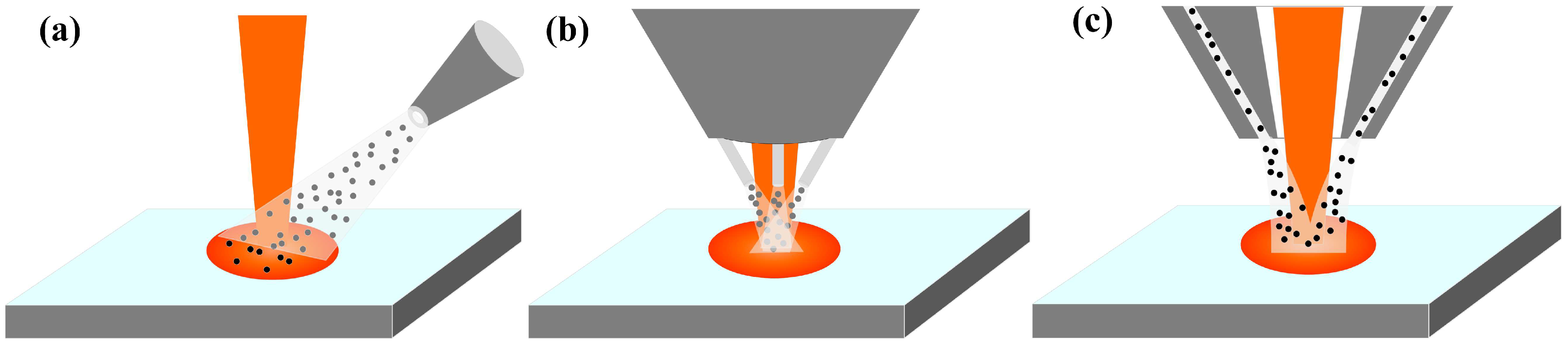
- Kumar, S.P.; Elangovan, S.; Mohanraj, R.; Srihari, B. Critical review of off-axial nozzle and coaxial nozzle for powder metal deposition. Mater. Today Proc. 2021, 46, 8066–8079. [Google Scholar] [CrossRef]
- Zhong, C.; Pirch, N.; Gasser, A.; Poprawe, R.; Schleifenbaum, J.H. The Influence of the Powder Stream on High-Deposition-Rate Laser Metal Deposition with Inconel 718. Metals 2017, 7, 443. [Google Scholar] [CrossRef]
- Gao, X.; Yao, X.X.; Niu, F.Y.; Zhang, Z. The influence of nozzle geometry on powder flow behaviors in directed energy deposition additive manufacturing. Adv Powder Technol. 2022, 33, 103487. [Google Scholar] [CrossRef]
- Pan, H.; Sparks, T.; Thakar, Y.D.; Liou, F. The Investigation of Gravity-Driven Metal Powder Flow in Coaxial Nozzle for Laser-Aided Direct Metal Deposition Process. J. Manuf. Sci. Eng. 2006, 128, 541–553. [Google Scholar] [CrossRef]
- Gabor, T.; Yun, H.; Akin, S.; Kim, K.H.; Park, J.K.; Jun, M.B.G. Continuous coaxial nozzle designs for improved powder focusing in direct laser metal deposition. J. Manuf. Process 2022, 83, 116–128. [Google Scholar] [CrossRef]
- Lamikiz, A.; Tabernero, I.; Ukar, E.; Martinez, S.; López de Lacalle, L.N. Current Designs of Coaxial Nozzles for Laser Cladding. Recent Pat. Mech. Eng. 2011, 4, 29–36. [Google Scholar] [CrossRef]
- Xia, Y.L.; Huang, Z.Z.; Chen, H.N.; Liang, X.D.; Lei, J.B. Numerical simulation and experimental investigation on powder transport of a new-type annular coaxial nozzle. Int. J. Adv. Manuf. Technol. 2021, 115, 2353–2364. [Google Scholar] [CrossRef]
- Su, P.; Li, H.; Yang, J.; Huang, D. Optimal design of structure parameters of coaxial powder feeding nozzle for laser cladding. J. Phys. Conf. Ser. 2021, 1798, 012050. [Google Scholar] [CrossRef]
- Tabernero, I.; Lamikiz, A.; Ukar, E.; López de Lacalle, L.N.; Angulo, C.; Urbikain, G. Numerical simulation and experimental validation of powder flux distribution in coaxial laser cladding. J. Mater. Process Technol. 2010, 210, 2125–2134. [Google Scholar] [CrossRef]
- Ruiz, J.E.; Arrizubieta, J.I.; Lamikiz, A.; Ostolaza, M. Non-symmetrical design of coaxial nozzle for minimal gas consumption on L-DED process for Ti6Al4V reactive alloy. J. Manuf. Process 2022, 78, 218–230. [Google Scholar] [CrossRef]
- Nogdhe, Y.; Rai, A.K.; Manjaiah, M. Numerical study of powder flow characteristics of coaxial nozzle direct energy deposition at different operating and design conditions. Prog. Addit. Manuf. 2025, 10, 701–723. [Google Scholar] [CrossRef]
- Liu, H.; He, X.L.; Yu, G.; Zhang, Z.B.; Li, S.X.; Zheng, C.Y.; Ning, W.J. Numerical simulation of powder transport behavior in laser cladding with coaxial powder feeding. Sci. China Phys. Mech. 2015, 58, 104701. [Google Scholar] [CrossRef]
- Chai, Q.; He, X.; Xing, Y.; Sun, G. Numerical study on the collision effect of particles in the gas-powder flow by coaxial nozzles for laser cladding. Opt. Laser Technol. 2023, 163, 109449. [Google Scholar] [CrossRef]
- Zekovic, S.; Dwivedi, R.; Kovacevic, R. Numerical simulation and experimental investigation of gas–powder flow from radially symmetrical nozzles in laser-based direct metal deposition. Int. J. Mach. Tool Manu. 2006, 47, 112–123. [Google Scholar] [CrossRef]
- Jardon, Z.; Guillaume, P.; Ertveldt, J.; Hinderdael, M.; Arroud, G. Offline powder-gas nozzle jet characterization for coaxial laser-based Directed Energy Deposition. Procedia CIRP 2020, 94, 281–287. [Google Scholar] [CrossRef]
- López-Martínez, A.; Ibarra-Medina, J.; García-Moreno, A.I.; Piedra, S.; Luis del Llano Vizcaya Martínez-Franco, E.; Megahed, M. Modeling and comparison of the powder flow dynamics for tilted annular and discrete-outlet nozzles in laser directed energy deposition. J. Manuf. Process. 2023, 99, 687–704. [Google Scholar] [CrossRef]
- Doubenskaia, M.; Kulish, A.; Sova, A.; Petrovskiy, P.; Smurov, I. Experimental and numerical study of gas-powder flux in coaxial laser cladding nozzles of Precitec. Surf. Coat. Technol. 2021, 406, 126672. [Google Scholar] [CrossRef]
- Zhou, H.; Yang, Y.; Wang, D.; Li, Y.; Zhang, S.; Tai, Z. Powder flow simulation of a ring-type coaxial nozzle and cladding experiment in laser metal deposition. Int. J. Adv. Manuf. Technol. 2022, 120, 8389–8400. [Google Scholar] [CrossRef]
- Zhang, B.; Coddet, C. Numerical study on the effect of pressure and nozzle dimension on particle distribution and velocity in laser cladding under vacuum base on CFD. J. Manuf. Process 2016, 23, 54–60. [Google Scholar] [CrossRef]
- Murer, M.; Furlan, V.; Formica, G.; Morganti, S.; Previtali, B.; Auricchio, F. Numerical simulation of particles flow in Laser Metal Deposition technology comparing Eulerian-Eulerian and Lagrangian-Eulerian approaches. J. Manuf. Process 2021, 68, 186–197. [Google Scholar] [CrossRef]
- Ostolaza, M.; Arrizubieta, J.I.; Lamikiz, A. CFD modelling of the powder segregation in multi-material laser directed energy deposition. Int. J. Therm. Sci. 2024, 198, 108885. [Google Scholar] [CrossRef]


| Parameters | a | b | s | φ | duc | doc |
|---|---|---|---|---|---|---|
| Values | 16 mm | 25 mm | 10 mm | 25° | 1 mm | 1 mm |
| Parameter | Values |
|---|---|
| Gas density (kg/m3) | 1.78 |
| Molecular viscosity (kg·m−1·s−1) | 2.125 × 10⁵ |
| Carrier gas inlet velocity (L/min) | 3 |
| Powder material | TC4 |
| Powder density (kg/m3) | 4500 |
| Powder feeding rate (g/min) | 3 |
| Min Diameter (μm) | Max Diameter (μm) | Average Diameter (μm) | Spread Parameter | Number of Diameters |
|---|---|---|---|---|
| 15 | 53 | 35 | 3.5 | 10 |
| Parameters | a | b | s | φ | duc | doc |
|---|---|---|---|---|---|---|
| Values | 17.5 mm | 25 mm | 10 mm | 24° | 0.5 mm | 0.5 mm |
| . | Case 1 | Case 2 | Case 3 | Case 4 |
|---|---|---|---|---|
| duc/mm | 3 | 2 | 1 | 2 |
| doc/mm | 1 | 1 | 1 | 1 |
| Input Section | Output Section | |||
|---|---|---|---|---|
| Optimal Parameters | Input shape | Outlet shape | Feeding inclination angle φ | Outlet gap doc |
| Values | Powder storage chamber structure | parallel type | 17° | 0.5 mm |
Disclaimer/Publisher’s Note: The statements, opinions and data contained in all publications are solely those of the individual author(s) and contributor(s) and not of MDPI and/or the editor(s). MDPI and/or the editor(s) disclaim responsibility for any injury to people or property resulting from any ideas, methods, instructions or products referred to in the content. |
© 2025 by the authors. Licensee MDPI, Basel, Switzerland. This article is an open access article distributed under the terms and conditions of the Creative Commons Attribution (CC BY) license (https://creativecommons.org/licenses/by/4.0/).
Share and Cite
Li, B.; Wang, W.; Li, D.; Liu, Z.; Ren, Y.; Wang, Y.; Yang, G. The Influence of the Annular Nozzle’s Structural Parameters on Powder Stream Convergence for Laser-Directed Energy Deposition. Materials 2025, 18, 2055. https://doi.org/10.3390/ma18092055
Li B, Wang W, Li D, Liu Z, Ren Y, Wang Y, Yang G. The Influence of the Annular Nozzle’s Structural Parameters on Powder Stream Convergence for Laser-Directed Energy Deposition. Materials. 2025; 18(9):2055. https://doi.org/10.3390/ma18092055
Chicago/Turabian StyleLi, Bobo, Weiyi Wang, Donglai Li, Zong Liu, Yuhang Ren, Yushi Wang, and Guang Yang. 2025. "The Influence of the Annular Nozzle’s Structural Parameters on Powder Stream Convergence for Laser-Directed Energy Deposition" Materials 18, no. 9: 2055. https://doi.org/10.3390/ma18092055
APA StyleLi, B., Wang, W., Li, D., Liu, Z., Ren, Y., Wang, Y., & Yang, G. (2025). The Influence of the Annular Nozzle’s Structural Parameters on Powder Stream Convergence for Laser-Directed Energy Deposition. Materials, 18(9), 2055. https://doi.org/10.3390/ma18092055