
Study on FEM Simulation Algorithm of Local Warm Forming of Advanced High-Strength Steel

 ,
,
Abstract
1. Introduction
2. Material Properties and Constitutive Model
2.1. Yield Criterion
2.2. Unidirectional Tensile Test
2.3. Stress–Strain Relationship
2.4. Temperature-Related Material Parameters
3. FEM Algorithm
3.1. Fracture Criteria
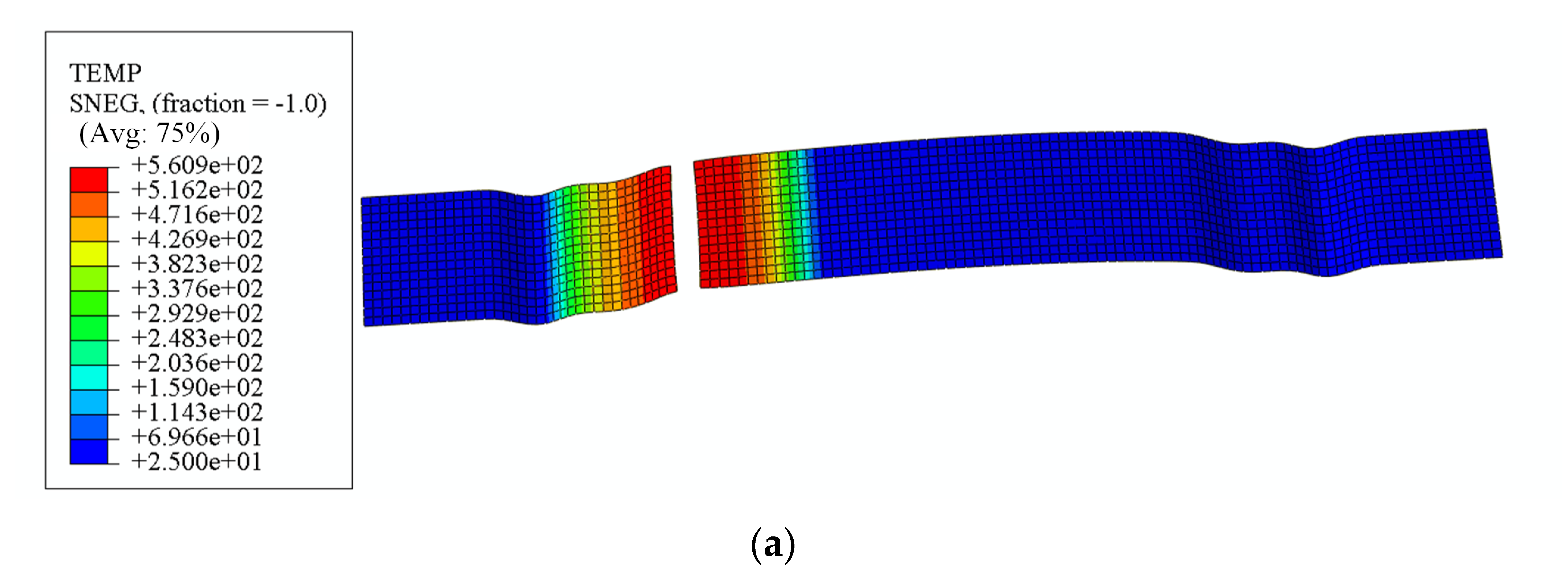
3.2. Heat Transfer Analysis
3.3. Algorithm for Local Warm Forming Simulation
- (1)
- The material parameters and initial temperature field localized in the sheet are set in Abaqus software.
- (2)
- Heat transfer analysis is carried out using the established heat transfer analysis model to obtain the temperature distribution of the sheet.
- (3)
- The VUMAT subroutine reads the updated temperature, material parameters, and strain increment matrix, and calculates the plastic strain increment in this analysis step by computing the test stress based on the strain increment according to the generalized Hooke’s law.
- (4)
- Determining whether the material is in the yielding stage, and if yielding does not occur, the stress is updated based on the value of the test stress.
- (5)
- If yielding occurs, calculating the equivalent plastic strain is performed and the stresses in each direction are updated, and the equivalent plastic strain and each plastic strain component are recorded in the user state variables.
- (6)
- Mechanical parameters, such as the equivalent fracture strain, Lode angle parameter, and stress triaxiality, are obtained by calculating the updated stress state.
- (7)
- Determining whether the corresponding unit is ruptured using the MMC fracture criterion that took into account the effect of temperature.
- (8)
- Updating energy, purely elastic analyses step update internal energy, elastic–plastic analyses step update internal energy with inelastic dissipation energy.
- (9)
- End.
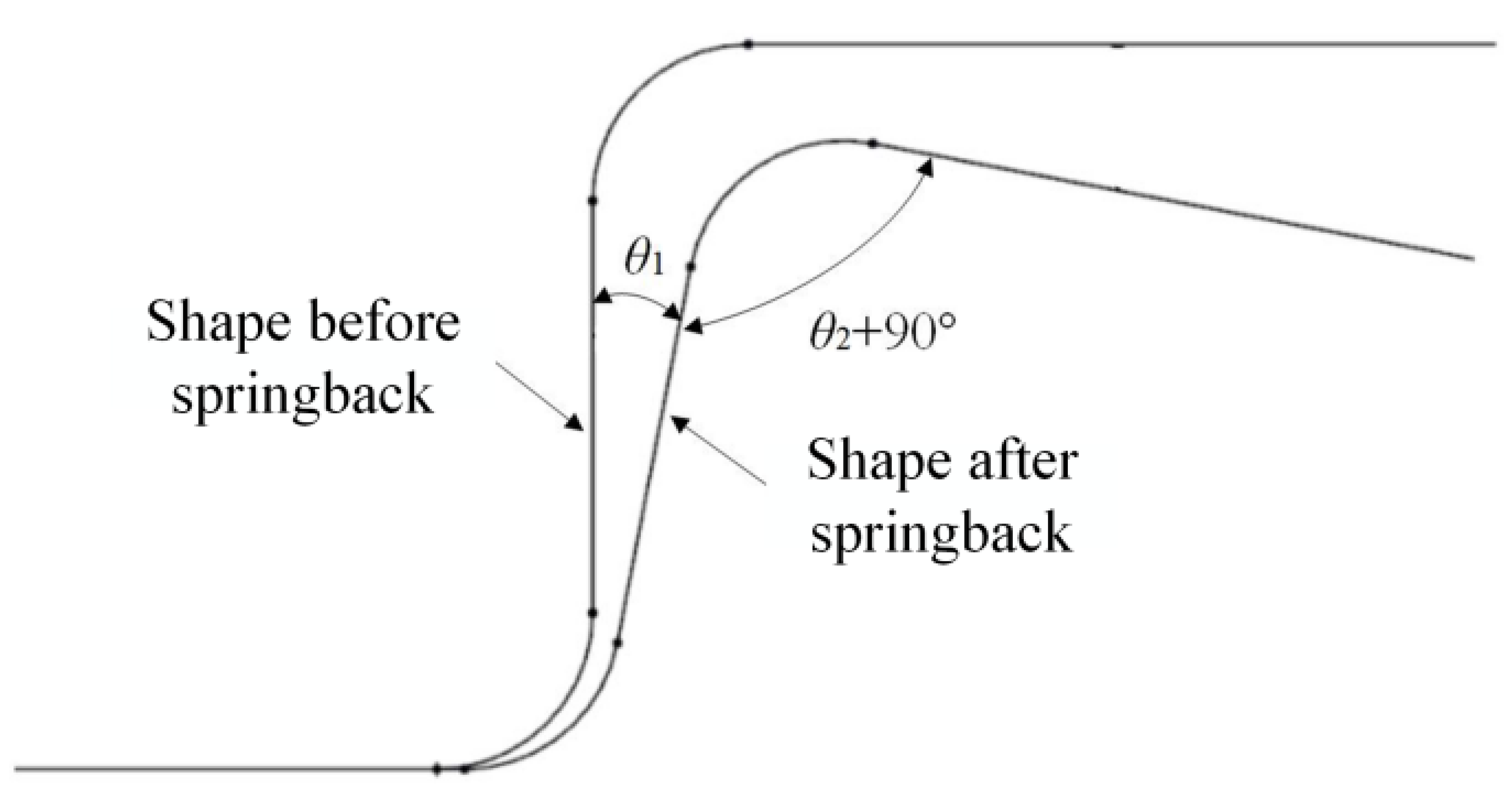
3.4. Springback Algorithm
- (1)
- At the end of the forming simulation, a restart is set up to start the springback analysis.
- (2)
- The initial temperature field localized in the sheet is set in Abaqus software. Heat transfer analysis is carried out using the established heat transfer analysis model to obtain the temperature distribution of the sheet.
- (3)
- After reading the temperature on each grid after updating, the UMAT subroutine calculates the elastic parameters and elastic Jacobi matrix for each cell based on the relationship between the elastic modulus and Poisson’s ratio and temperature, calculates the stresses based on the strains, and reads the value of each strain stored in the state variables from the previous step.
- (4)
- The UMAT subroutine incorporates the current temperature into Equations (3)–(5), calculates the yield stress of each unit at the current temperature by combining the current equivalent plastic strain, and substitutes it into the Swift hardening criterion. The deviatoric stress is calculated, and the equivalent stress is calculated according to Equation (1).
- (5)
- Determining the yielding situation, if yielding does not occur, then go to the purely elastic incremental step of the calculation process to calculate the relevant variables, and the equivalent plastic strain is 0.
- (6)
- If yielding occurs, the process of calculating each stress–strain value, equivalent plastic strain and updating the elastic–plastic Jacobi matrix is carried out in the elastic–plastic incremental step.
- (7)
- Each state variable is updated and stored.
- (8)
- End.
4. Verification
4.1. Forming Test
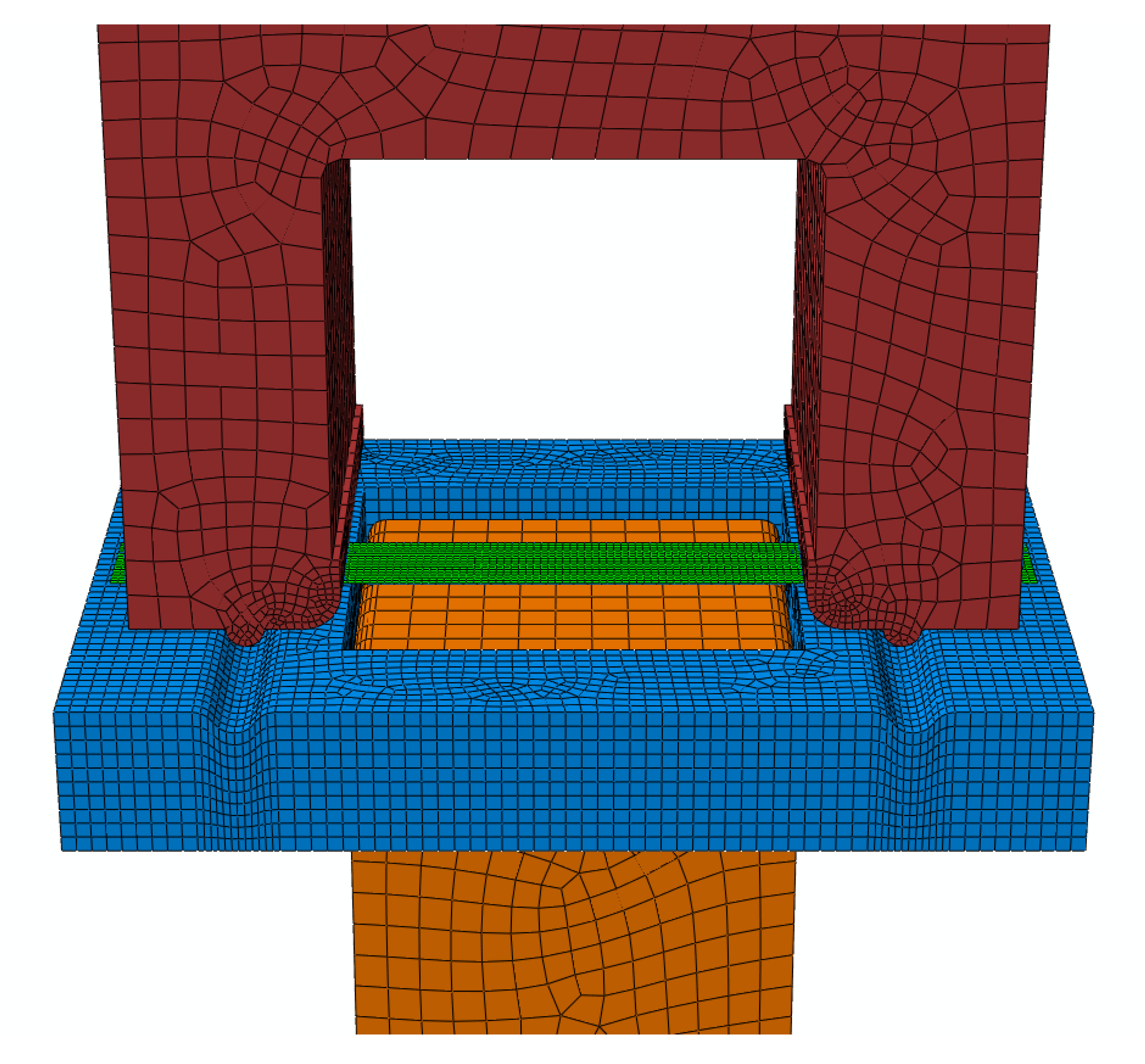
4.2. Simulation
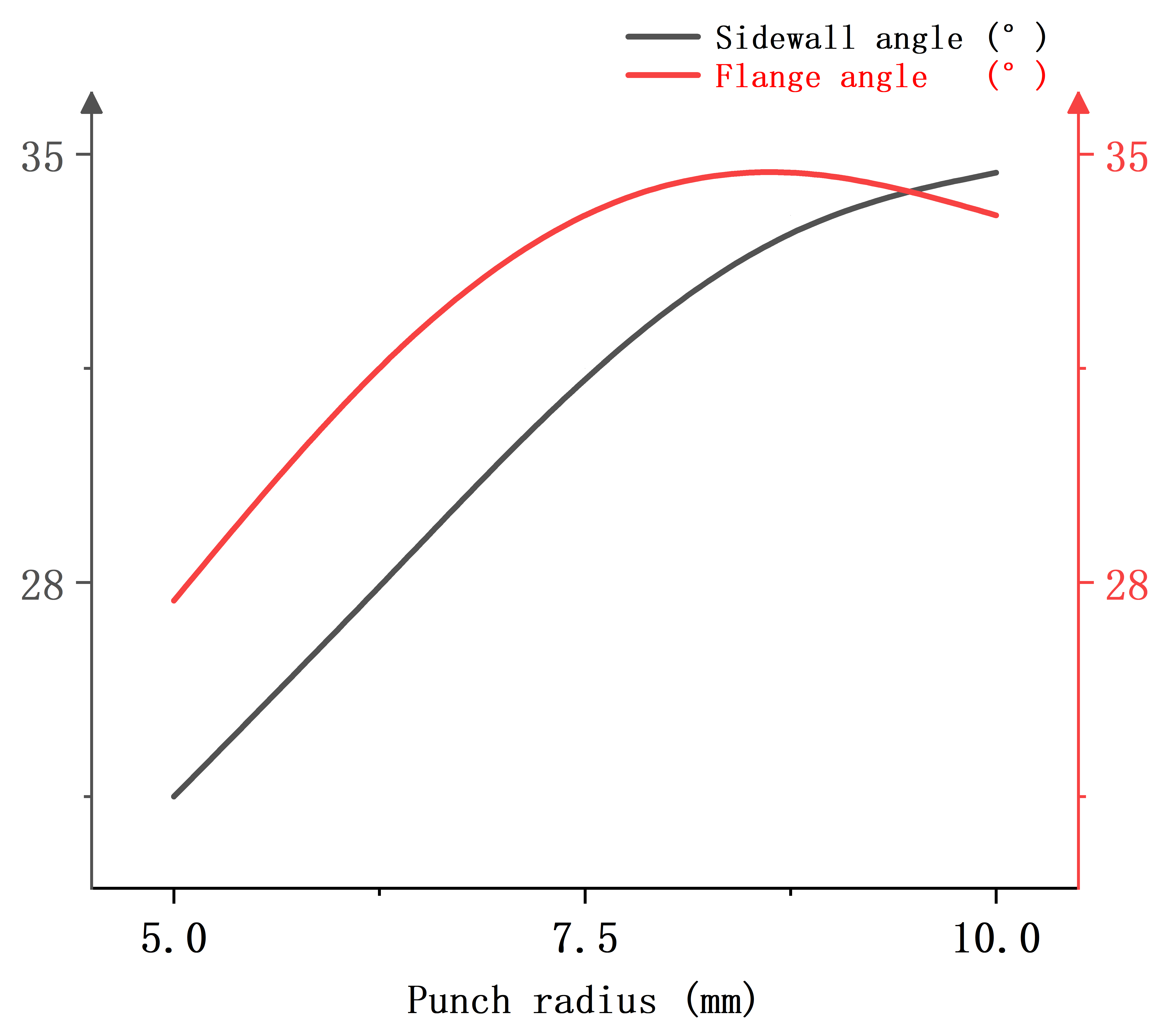
4.3. Factors Analysis of Affecting Springback
- (1)
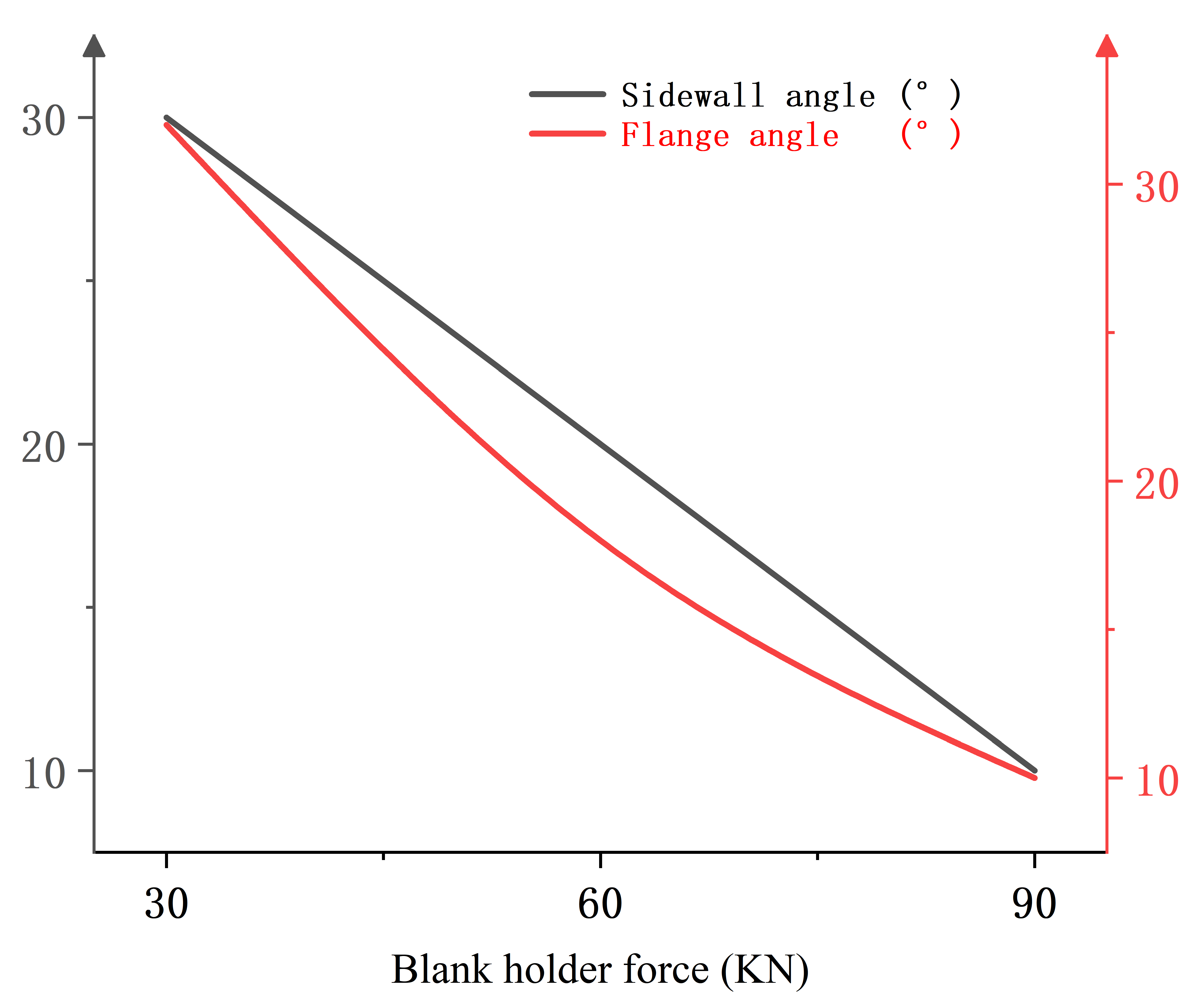
- The springback of the sheet can be suppressed by increasing the blank holder force and decreasing the punch radius, with the two factors exerting the most significant impact on the springback behavior.
- (2)
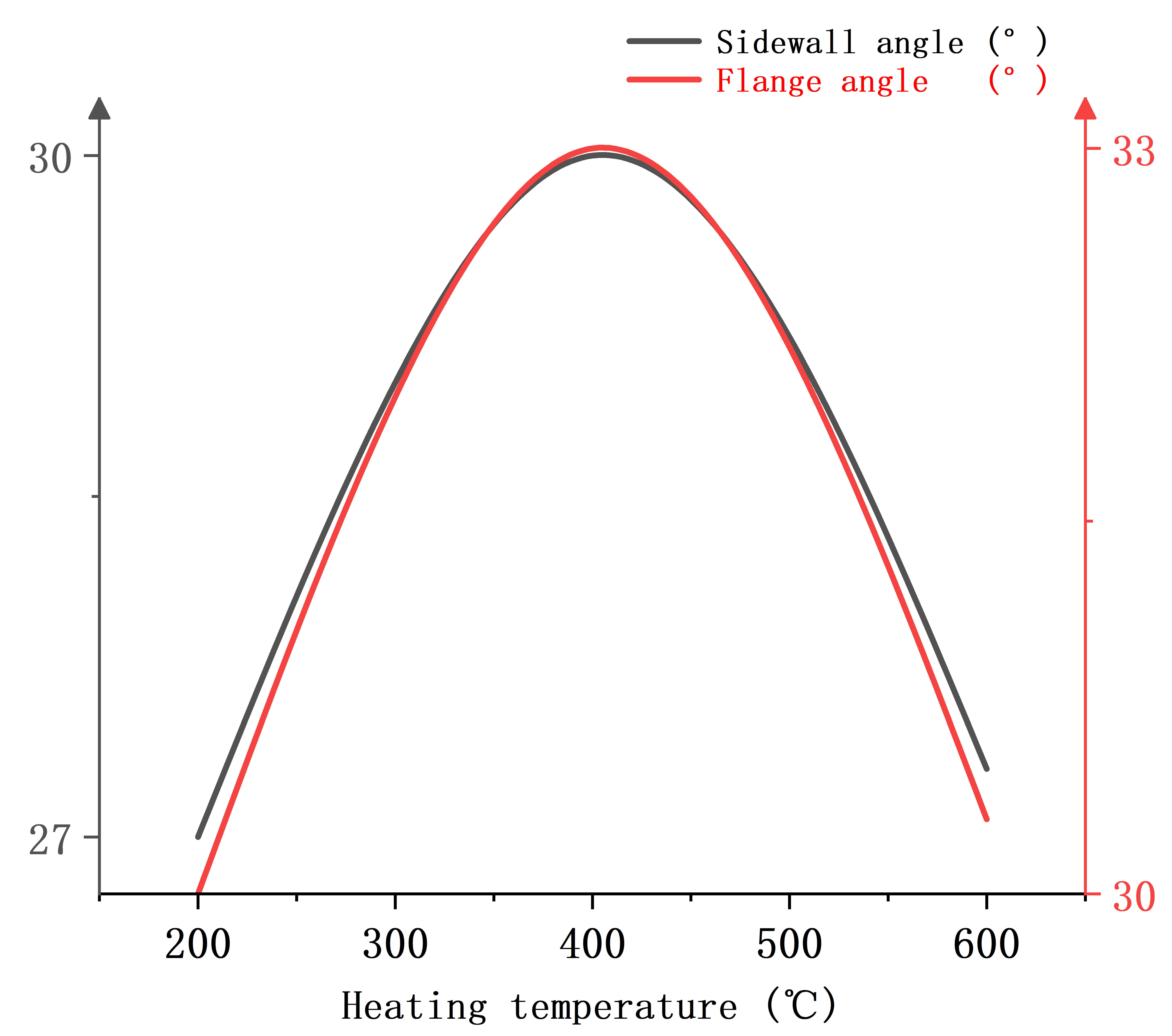
- As the heating temperature increases, the springback volume of the plate initially enlarges and subsequently diminishes. This phenomenon is attributed to the occurrence of “blue brittleness” when the plate is heated. The “blue brittleness” enhances the strength of the sheet, leading to an increase in springback within the temperature range where this brittleness manifests.
- (3)
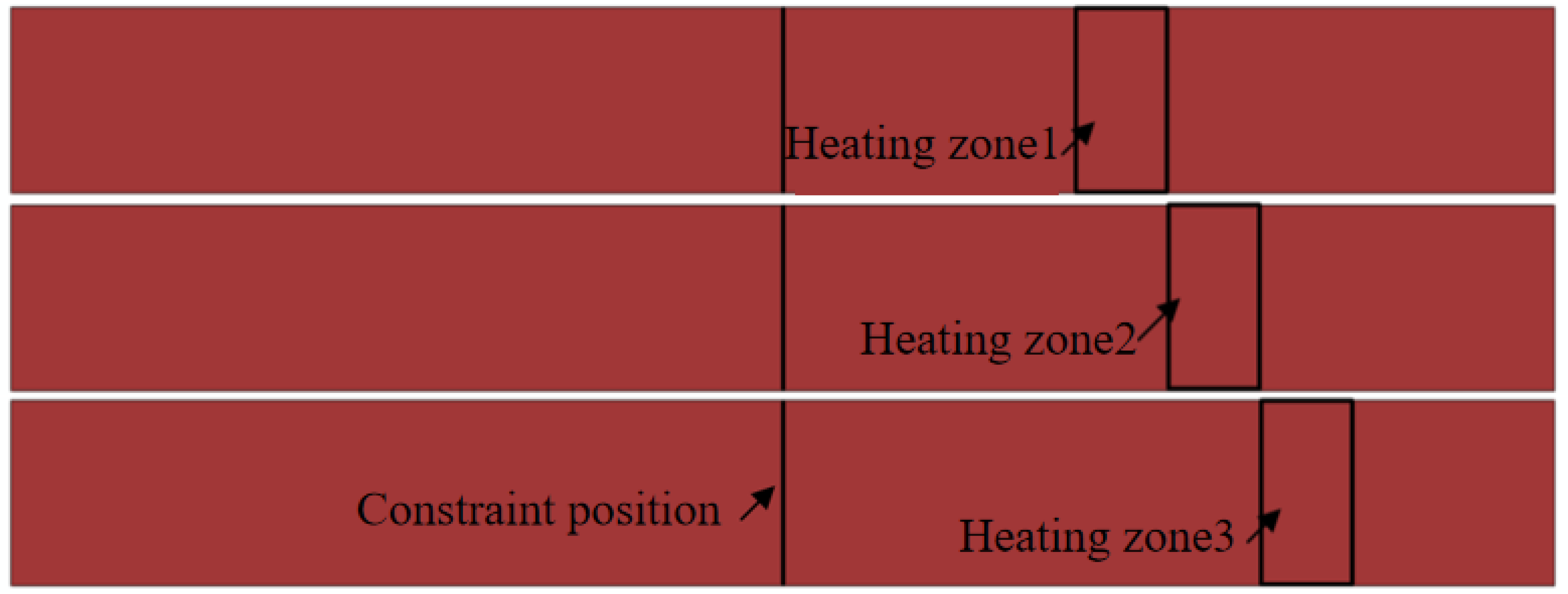
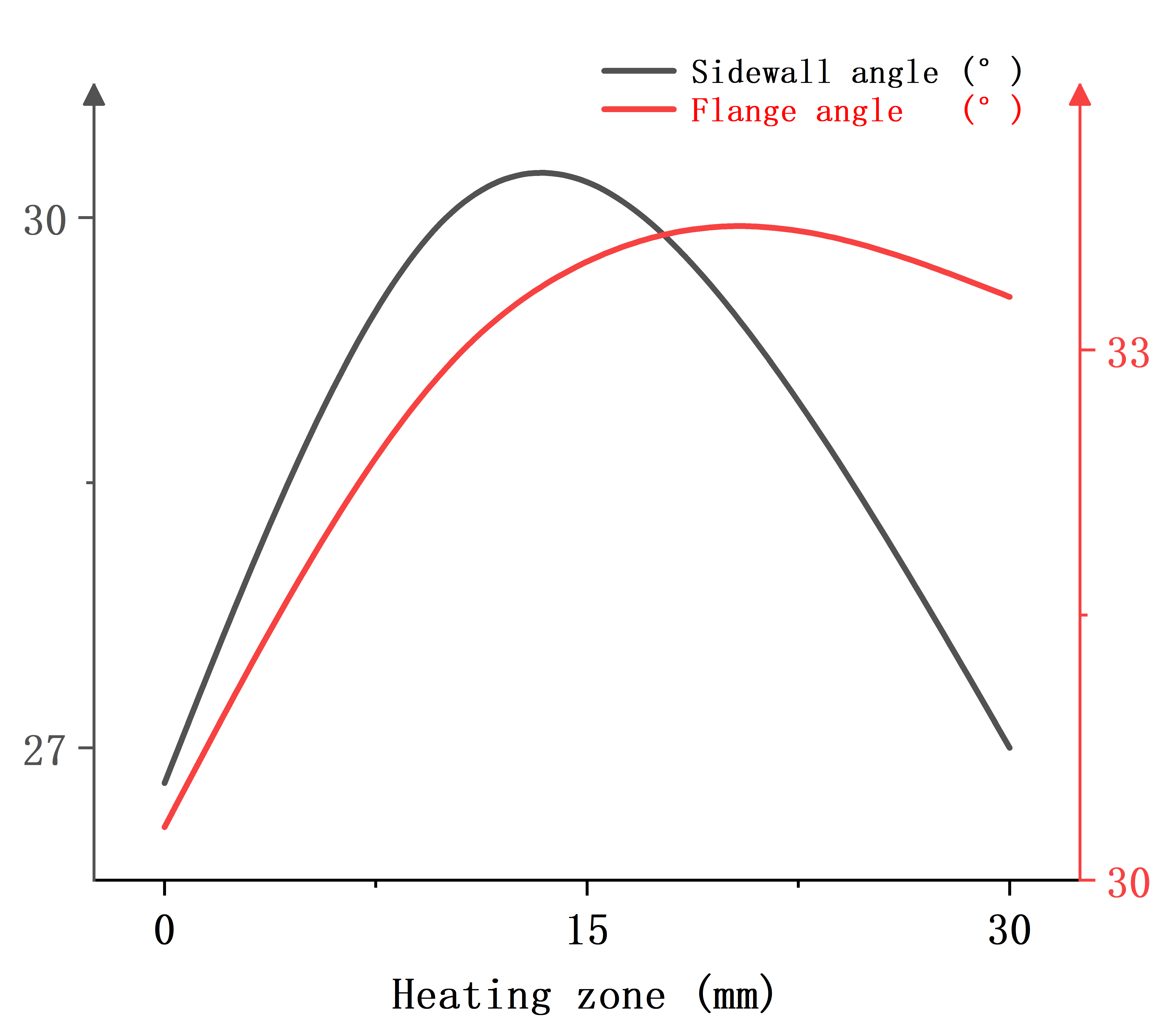
- There is a higher springback when only one end of the feature zone is heated or when the temperature difference between the two ends of the feature is too large.
5. Conclusions
- (1)
- Adopting higher-order anisotropic constitutive models to enhance universality.
- (2)
- Exploring synergistic processes combining local warm forming with additive manufacturing to advance lightweight, high-performance automotive components.
Author Contributions
Funding
Institutional Review Board Statement
Informed Consent Statement
Data Availability Statement
Conflicts of Interest
References
- Yang, X.; Jia, C.; Zang, L.; Wang, L.; Li, Z. Study on the formability of duplex steel with different strength grades. Sichuan Metall. 2019, 41, 26–28. (In Chinese) [Google Scholar]
- Yan, Y.; Wang, H.; Li, Q. The inverse parameter identification of Hill 48 yield criterion and its verification in press bending and roll forming process simulations. J. Manuf. Process. 2015, 20, 46–53. [Google Scholar] [CrossRef]
- Ozturk, F.; Toros, S.; Kilic, S. Effects of Anisotropic Yield Functions on Prediction of Forming Limit Diagrams of DP600 Advanced High Strength Steel. Procedia Eng. 2014, 81, 760–765. [Google Scholar] [CrossRef]
- Hajbarati, H.; Zajkani, A.; Gholipour, J. Temperature-dependent anisotropic hardening behavior of DP steels: A comparative study of Swift and Arrhenius-type models. Mater. Des. 2024, 238, 112345. [Google Scholar]
- Xu, Z.; Shan, D. Aluminum alloy sheet heat treatment and stamping integration technology in car body manufacturing. MST 2018, 26, 1–9. (In Chinese) [Google Scholar]
- Pepelnjak, T.; Kayhan, E.; Kaftanoglu, B. Analysis of non-isothermal warm deep drawing of dual-phase DP600 steel. Int. J. Mater. Form. 2019, 12, 223–240. [Google Scholar] [CrossRef]
- Li, D. Simulation study on the formability of DP780 under high temperature conditions. Automob. Parts 2020, 08, 22–25. (In Chinese) [Google Scholar]
- Bielak, R.; Bammer, F.; Otto, A.; Stiglbrunner, C.; Colasse, C.; Murzin, S.P. Simulation of forming processes with local heating of dual phase steels with use of laser beam shaping systems. Comput. Opt. 2016, 40, 659–667. [Google Scholar] [CrossRef]
- Karaağaç, İ.; Kabakçi, M.O.; Başdoğan, Z. The effects of laser-assisted heat treatment on warm formability of dual-phase materials. Ironmak. Steelmak. 2023, 50, 984–990. [Google Scholar] [CrossRef]
- Zhou, J.; Yang, X.; Mu, Y.; Liu, S.; Wang, B. Numerical simulation and experimental investigation of tailored hot stamping of boron steel by partial heating. J. Mater. Res. Technol. 2021, 14, 1347–1365. [Google Scholar] [CrossRef]
- Wang, K.; Zhu, B.; Wang, L.; Wang, Y.; Zhang, Y. Tailored properties of hot stamping steel by resistance heating with local temperature control. Procedia Manuf. 2018, 15, 1087–1094. [Google Scholar] [CrossRef]
- Lee, E.H.; Yang, D.Y.; Yoon, J.W.; Yang, W.H. Numerical modeling and analysis for forming process of dual-phase 980 steel exposed to infrared local heating. IJSS 2015, 75, 211–224. [Google Scholar] [CrossRef]
- Kim, K.Y.; Lee, E.H.; Park, S.H.; Kang, Y.H.; Park, J.Y. An Infrared Local-Heat-Assisted Cold Stamping Process for Martensitic Steel and Application to an Auto Part. Metals 2020, 10, 1543. [Google Scholar] [CrossRef]
- Küçüktürk, G.; Tahta, M.; Gürün, H.; Karaağaç, I. Evaluation of the Effects of Local Heating on Springback Behaviour for AHSS Docol 1400 Sheet Metal. Trans. Famena 2022, 46, 51–62. [Google Scholar] [CrossRef]
- Sen, N. Experimental investigation of the formability of ultrahigh-strength sheet material using local heat treatment. Ironmak 2020, 47, 93–99. [Google Scholar] [CrossRef]
- Boyu, P.; Fuhui, S.; Sebastian, M. Constitutive modeling of temperature and strain rate effects on anisotropy and strength differential properties of metallic materials. Mech. Mater. 2023, 184, 104714. [Google Scholar]
- Zhao, H.; Peng, Y.; Shi, B. Research progress on anisotropic constitutive models of metallic materials. Plast. Eng. 2022, 29, 32–42. (In Chinese) [Google Scholar]
- Zhang, D. Rebound Theory and Finite Element Numerical Simulation of Sheet Metal Stamping Forming; Shanghai Jiao Tong University: Shanghai, China, 2006. (In Chinese) [Google Scholar]
- Cui, H.; Li, D.; Fu, Q.; Lu, Z.; Xu, J.; Jiang, N. Research on Forming Limit Stress Diagram of Advanced High Strength Dual-Phase Steel Sheets. Materials 2023, 16, 4543. [Google Scholar] [CrossRef]
- Liu, L.; Li, L.; Liang, Z.; Huang, M.; Peng, Z.; Gao, J.; Luo, Z. Towards ultra-high strength dual-phase steel with excellent damage tolerance: The effect of martensite volume fraction. Int. J. Plast. 2023, 170, 103778. [Google Scholar] [CrossRef]
- Liu, L.; Li, L.; He, J.; Liang, Z.; Peng, Z.; Gao, J.; Luo, Z.; Huang, M. The unexpected low fracture toughness of dual-phase steels caused by ferrite/martensite interface decohesion. Scr. Mater. 2024, 244, 116030. [Google Scholar] [CrossRef]
- Xu, Y.; Dan, W.; Li, C.; Zhang, W. Experimental Study of the Micromechanical Behavior of Ferrite in DP Steel Under Various Stress States. Met. Mater. Trans. A 2020, 51, 4511–4523. [Google Scholar] [CrossRef]
- Swift, H.W. Plastic instability under plane stress. JMPS 1952, 1, 1–18. [Google Scholar] [CrossRef]
- Lu, Z. Springback Simulation Method of Local Warm Forming for Advanced High-Strength Dual-Phase Steel Sheet; Shandong University of Technology: Zibo, China, 2024. (In Chinese) [Google Scholar]
- Sung, J.H.; Kim, J.H.; Wagoner, R.H. A plastic constitutive equation incorporating strain, strain-rate, and temperature. IJP 2010, 26, 1746–1771. [Google Scholar] [CrossRef]
- Hajbarati, H.; Zajkani, A. A novel finite element simulation of hot stamping process of DP780 steel based on the Chaboche thermomechanically hardening model. Int. J. Adv. Manuf. Technol. 2020, 111, 2705–2718. [Google Scholar] [CrossRef]
- Luo, M.; Wierzbicki, T. Numerical failure analysis of a stretch-bending test on dual-phase steel sheets using a phenomenological fracture model. IJSS 2010, 47, 3084–3102. [Google Scholar] [CrossRef]
- Bai, Y.; Wierzbicki, T. A new model of metal plasticity and fracture with pressure and Lode dependence. IJP 2007, 24, 1071–1096. [Google Scholar] [CrossRef]
- Bai, Y.; Wierzbicki, T. Application of extended Mohr-Coulomb criterion to ductile fracture. Int. J. Fract. 2010, 161, 1–20. [Google Scholar] [CrossRef]
- Li, Y.; Li, D.; Song, H.; Wang, Y.; Wu, D. Temperature Dependency of Modified Mohr-Coulomb Criterion Parameters for Advanced High Strength Dual-Phase Steel DP780. Metals 2024, 14, 721. [Google Scholar] [CrossRef]
- Tao, Y. Research on the Optimization of Back-Arc Hot Stamping Process and Springback Compensation of Large Hollow Blades; Chongqing University: Chongqing, China, 2016. (In Chinese) [Google Scholar]


| C | Si | Mn | P | S | Alt |
|---|---|---|---|---|---|
| 0.1 | 0.16 | 20.2 | 0.008 | 0.003 | 0.039 |
| Steel | r0 | r45 | r90 | |
|---|---|---|---|---|
| DP780 | 0.79 | 0.84 | 0.79 | 0.82 |
| F | G | H | L | M | N |
|---|---|---|---|---|---|
| 0.56 | 0.56 | 0.44 | 1.5 | 1.5 | 1.5 |
| Serial Number | Punch Radius (mm) | Blank Holder Force (KN) | Stamping Depth (mm) | Heating Temperature (°C) |
|---|---|---|---|---|
| 1 | 10 | 48 | 9 | 600 |
| 2 | 7 | 30 | 12 | 275 |
| 3 | 7 | 20 | 9 | 325 (Integral Heating) |
| 4 | 10 | 40 | 9 | 378 (Integral Heating) |
| 5 | 7 | 40 | 12 | 400 |
| Level of Factors | Blank Holder Force X1 (KN) | Heating Temperature X2 (°C) | Heating Zone X3 (mm) | Punch Radius X4 (mm) |
|---|---|---|---|---|
| −1 | 30 | 200 | 0 | 5 |
| 0 | 60 | 400 | 15 | 7.5 |
| 1 | 90 | 600 | 30 | 10 |
| Serial Number | X1 (kN) | X2 (°C) | X3 (mm) | X4 (mm) | θ1 | θ2 |
|---|---|---|---|---|---|---|
| 1 | 30 | 200 | 15 | 7.5 | 27.09 | 30.75 |
| 2 | 90 | 200 | 15 | 7.5 | 16 | 9.76 |
| 3 | 30 | 600 | 15 | 7.5 | 28.1 | 31.47 |
| 4 | 90 | 600 | 15 | 7.5 | 14.31 | 7.43 |
| 5 | 60 | 400 | 0 | 5 | 13.34 | 5.81 |
| 6 | 60 | 400 | 30 | 5 | 12.84 | 7.8 |
| 7 | 60 | 400 | 0 | 10 | 25.29 | 18.83 |
| 8 | 60 | 400 | 30 | 10 | 21.26 | 19.71 |
| 9 | 30 | 400 | 15 | 5 | 23.77 | 27.58 |
| 10 | 90 | 400 | 15 | 5 | 6.3 | 1.45 |
| 11 | 30 | 400 | 15 | 10 | 34.41 | 35.19 |
| 12 | 90 | 400 | 15 | 10 | 15.79 | 8.57 |
| 13 | 60 | 200 | 0 | 7.5 | 21.58 | 15.22 |
| 14 | 60 | 600 | 0 | 7.5 | 21.28 | 15.31 |
| 15 | 60 | 200 | 30 | 7.5 | 16.73 | 15.61 |
| 16 | 60 | 600 | 30 | 7.5 | 17.62 | 17.07 |
| 17 | 30 | 400 | 0 | 7.5 | 28.73 | 30.12 |
| 18 | 90 | 400 | 0 | 7.5 | 15.53 | 8.38 |
| 19 | 30 | 400 | 30 | 7.5 | 24.33 | 33.31 |
| 20 | 90 | 400 | 30 | 7.5 | 12.37 | 9.32 |
| 21 | 60 | 200 | 15 | 5 | 13.48 | 5.85 |
| 22 | 60 | 600 | 15 | 5 | 14.08 | 6.29 |
| 23 | 60 | 200 | 15 | 10 | 24.59 | 18.1 |
| 24 | 60 | 600 | 15 | 10 | 24.71 | 18.6 |
| 25 | 60 | 400 | 15 | 7.5 | 21.23 | 15.48 |
| 26 | 60 | 400 | 15 | 7.5 | 21.23 | 15.48 |
| 27 | 60 | 400 | 15 | 7.5 | 21.23 | 15.48 |
| 28 | 60 | 400 | 15 | 7.5 | 21.23 | 15.48 |
| 29 | 60 | 400 | 15 | 7.5 | 21.23 | 15.48 |
| Source | Sum of Squares | Degrees of Freedom | Mean Square | F-Value | p-Value | Result |
|---|---|---|---|---|---|---|
| Model | 1038.71 | 22 | 47.21 | 8034.53 | <0.0001 | significant |
| A-A | 325.62 | 1 | 325.62 | 55,411.93 | <0.0001 | highly significant |
| B-B | 0.1296 | 1 | 0.1296 | 22.05 | 0.0033 | |
| C-C | 5.13 | 1 | 5.13 | 873.02 | <0.0001 | highly significant |
| D-D | 103.73 | 1 | 103.73 | 17,652.72 | <0.0001 | highly significant |
| AB | 1.82 | 1 | 1.82 | 310.14 | <0.0001 | highly significant |
| AC | 0.3844 | 1 | 0.3844 | 65.41 | 0.0002 | |
| AD | 0.3306 | 1 | 0.3306 | 56.26 | 0.0003 | |
| BC | 0.354 | 1 | 0.354 | 60.25 | 0.0002 | |
| BD | 0.0576 | 1 | 0.0576 | 9.8 | 0.0203 | |
| CD | 3.12 | 1 | 3.12 | 530.13 | <0.0001 | highly significant |
| A2 | 1.59 | 1 | 1.59 | 271.38 | <0.0001 | highly significant |
| B2 | 1.03 | 1 | 1.03 | 175.88 | <0.0001 | highly significant |
| C2 | 14.26 | 1 | 14.26 | 2427.35 | <0.0001 | highly significant |
| D2 | 16.87 | 1 | 16.87 | 2871.59 | <0.0001 | highly significant |
| A2B | 0.245 | 1 | 0.245 | 41.69 | 0.0007 | |
| A2C | 1.15 | 1 | 1.15 | 195.29 | <0.0001 | highly significant |
| A2D | 0.0072 | 1 | 0.0072 | 1.23 | 0.3107 | |
| AB2 | 15.71 | 1 | 15.71 | 2673.07 | <0.0001 | highly significant |
| AC2 | 14.93 | 1 | 14.93 | 2541.21 | <0.0001 | highly significant |
| B2C | 1.98 | 1 | 1.98 | 336.95 | <0.0001 | highly significant |
| B2D | 0.2346 | 1 | 0.2346 | 39.92 | 0.0007 | |
| BC2 | 0.0021 | 1 | 0.0021 | 0.3595 | 0.5707 | |
| Residual | 0.0353 | 6 | 0.0059 | |||
| Lack of Fit | 0.0353 | 2 | 0.0176 | |||
| Pure Error | 0 | 4 | 0 | |||
| Cor Total | 1038.74 | 28 |
| Source | Sum of Squares | Degrees of Freedom | Mean Square | F-Value | p-Value | Result |
|---|---|---|---|---|---|---|
| Model | 2338.72 | 22 | 106.31 | 261.22 | <0.0001 | significant |
| A-A | 695.64 | 1 | 695.64 | 1709.35 | <0.0001 | highly significant |
| B-B | 0.2209 | 1 | 0.2209 | 0.5428 | 0.4891 | |
| C-C | 2.06 | 1 | 2.06 | 5.06 | 0.0655 | |
| D-D | 155.38 | 1 | 155.38 | 381.79 | <0.0001 | highly significant |
| AB | 2.33 | 1 | 2.33 | 5.71 | 0.054 | |
| AC | 1.27 | 1 | 1.27 | 3.11 | 0.1283 | |
| AD | 0.06 | 1 | 0.06 | 0.1475 | 0.7142 | |
| BC | 0.4692 | 1 | 0.4692 | 1.15 | 0.3242 | |
| BD | 0.0009 | 1 | 0.0009 | 0.0022 | 0.964 | |
| CD | 0.308 | 1 | 0.308 | 0.7569 | 0.4177 | |
| A2 | 153.37 | 1 | 153.37 | 376.86 | <0.0001 | highly significant |
| B2 | 0.894 | 1 | 0.894 | 2.2 | 0.1888 | |
| C2 | 0.4301 | 1 | 0.4301 | 1.06 | 0.3436 | |
| D2 | 43.22 | 1 | 43.22 | 106.2 | <0.0001 | highly significant |
| A2B | 0.8128 | 1 | 0.8128 | 2 | 0.2073 | |
| A2C | 0.1985 | 1 | 0.1985 | 0.4876 | 0.5111 | |
| A2D | 13.01 | 1 | 13.01 | 31.96 | 0.0013 | |
| AB2 | 7.45 | 1 | 7.45 | 18.31 | 0.0052 | |
| AC2 | 6.16 | 1 | 6.16 | 15.14 | 0.0081 | |
| B2C | 0.0648 | 1 | 0.0648 | 0.1592 | 0.7037 | |
| B2D | 0.0171 | 1 | 0.0171 | 0.042 | 0.8443 | |
| BC2 | 0.0465 | 1 | 0.0465 | 0.1143 | 0.7468 | |
| Residual | 2.44 | 6 | 0.407 | |||
| Lack of Fit | 2.44 | 2 | 1.22 | |||
| Pure Error | 0 | 4 | 0 | |||
| Cor Total | 2341.16 | 28 |
Disclaimer/Publisher’s Note: The statements, opinions and data contained in all publications are solely those of the individual author(s) and contributor(s) and not of MDPI and/or the editor(s). MDPI and/or the editor(s) disclaim responsibility for any injury to people or property resulting from any ideas, methods, instructions or products referred to in the content. |
© 2025 by the authors. Licensee MDPI, Basel, Switzerland. This article is an open access article distributed under the terms and conditions of the Creative Commons Attribution (CC BY) license (https://creativecommons.org/licenses/by/4.0/).
Share and Cite
Wang, T.; Li, D.; Wang, X.-K.; Zhu, H.-P.; Liu, J.-J.; Jiang, N.; Feng, X.-Z.; Liu, S.-X. Study on FEM Simulation Algorithm of Local Warm Forming of Advanced High-Strength Steel. Materials 2025, 18, 1900. https://doi.org/10.3390/ma18091900
Wang T, Li D, Wang X-K, Zhu H-P, Liu J-J, Jiang N, Feng X-Z, Liu S-X. Study on FEM Simulation Algorithm of Local Warm Forming of Advanced High-Strength Steel. Materials. 2025; 18(9):1900. https://doi.org/10.3390/ma18091900
Chicago/Turabian StyleWang, Tao, Di Li, Xiao-Kun Wang, Hong-Pai Zhu, Jun-Jie Liu, Ning Jiang, Xiao-Zhi Feng, and Shao-Xun Liu. 2025. "Study on FEM Simulation Algorithm of Local Warm Forming of Advanced High-Strength Steel" Materials 18, no. 9: 1900. https://doi.org/10.3390/ma18091900
APA StyleWang, T., Li, D., Wang, X.-K., Zhu, H.-P., Liu, J.-J., Jiang, N., Feng, X.-Z., & Liu, S.-X. (2025). Study on FEM Simulation Algorithm of Local Warm Forming of Advanced High-Strength Steel. Materials, 18(9), 1900. https://doi.org/10.3390/ma18091900