Corrosion of Porous Building Ceramics Caused by Double Sulphate Salt


Abstract
1. Introduction
- Presence of soluble salt sources, whether internal (within the material) or external.
- The material must feature capillary pores.

2. Materials and Methods
- Clay (10 vol.%) from the Oleśnica deposit (Świętokrzyskie Voivodeship, Poland), formed in Miocene in marine conditions (therefore it contains many carbonates), used in one of the largest wall ceramics factories in Europe, Wienerberger Oleśnica,
- quartz sand (10 vol.%), introduced to reduce the plasticity of the clay raw material,
- sawdust (15 vol.%), which creased the porosity of the fired material.
3. Results
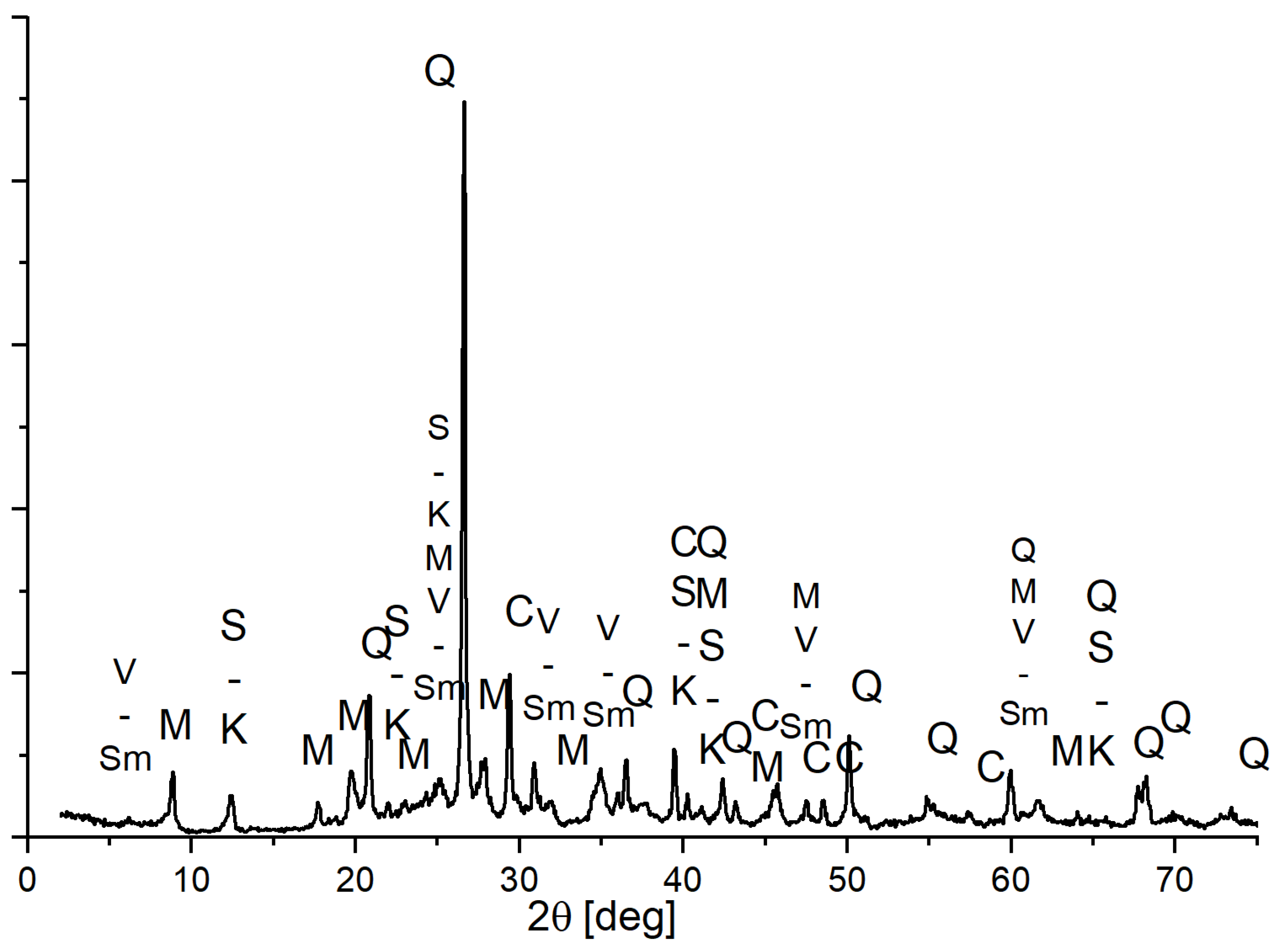
3.1. Raw Materials
3.2. Changes in Basic Physical Parameters of Ceramics
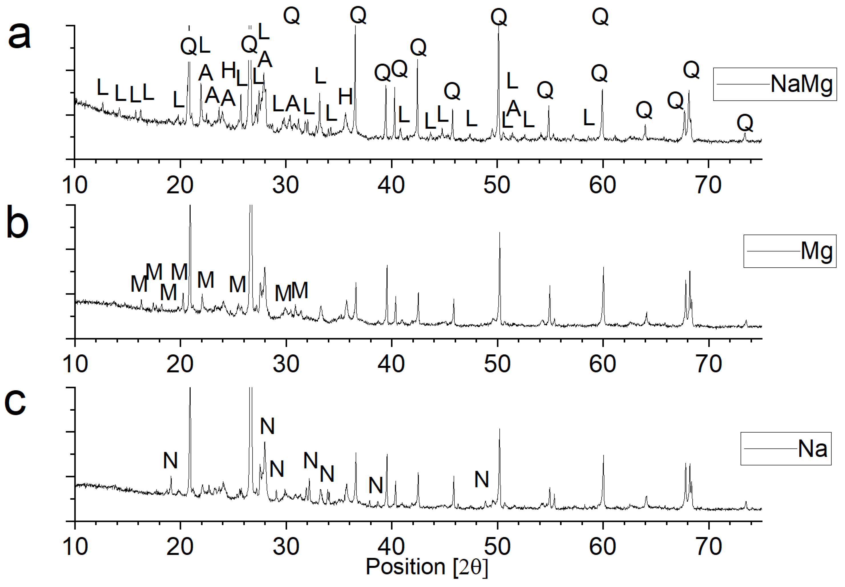
3.3. Phase Composition of Materials Conditioned in Corrosive Solutions
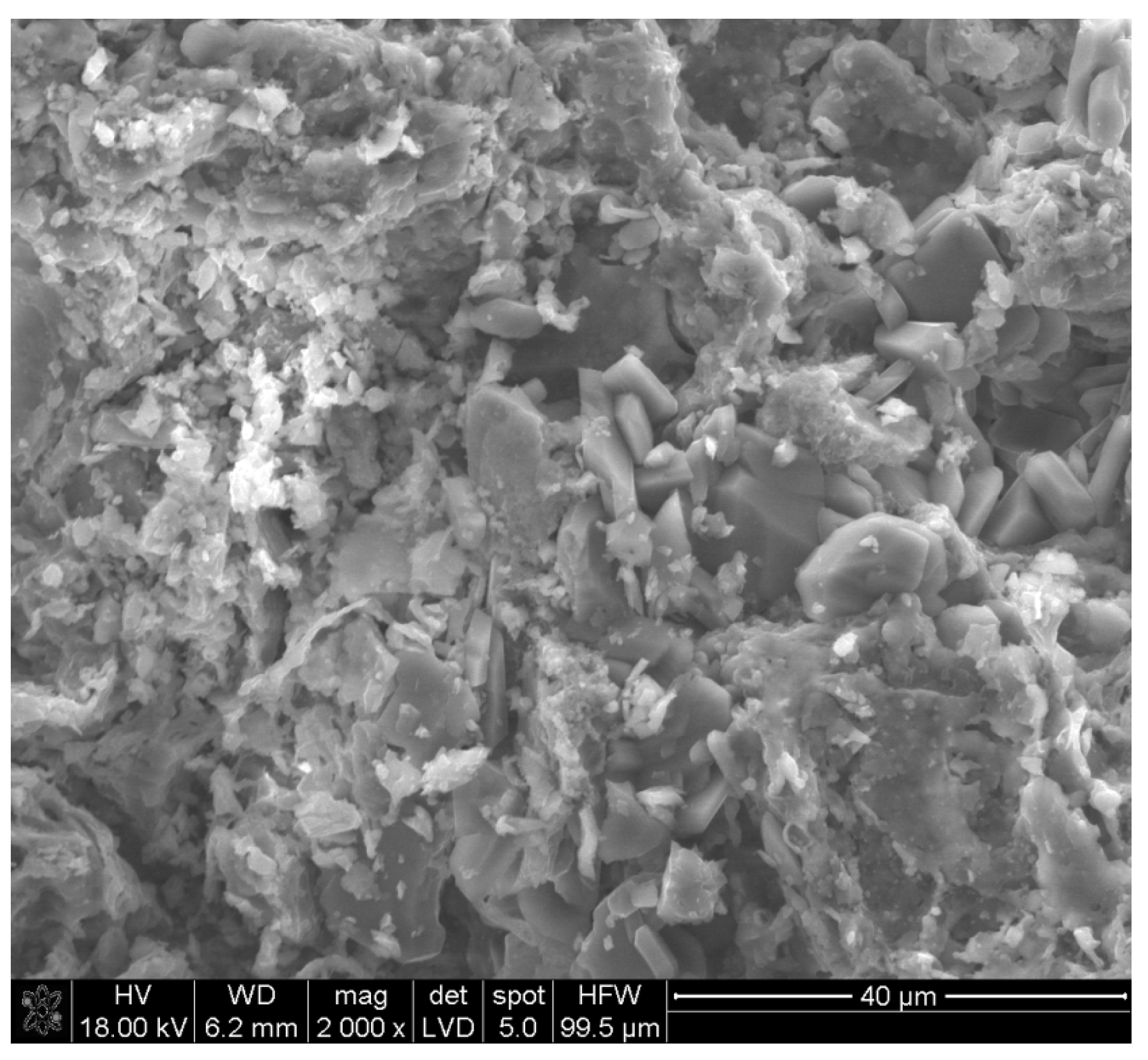
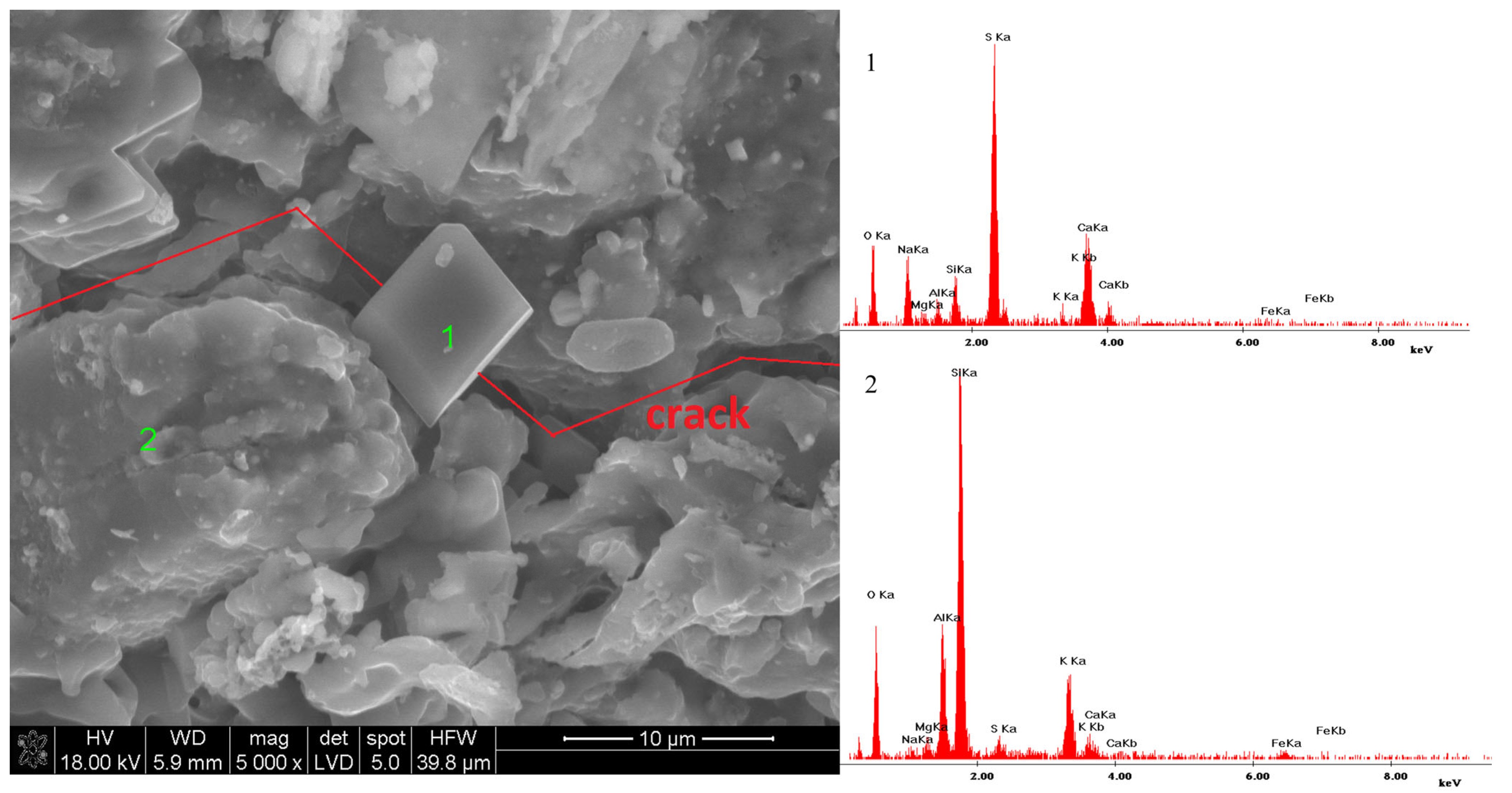
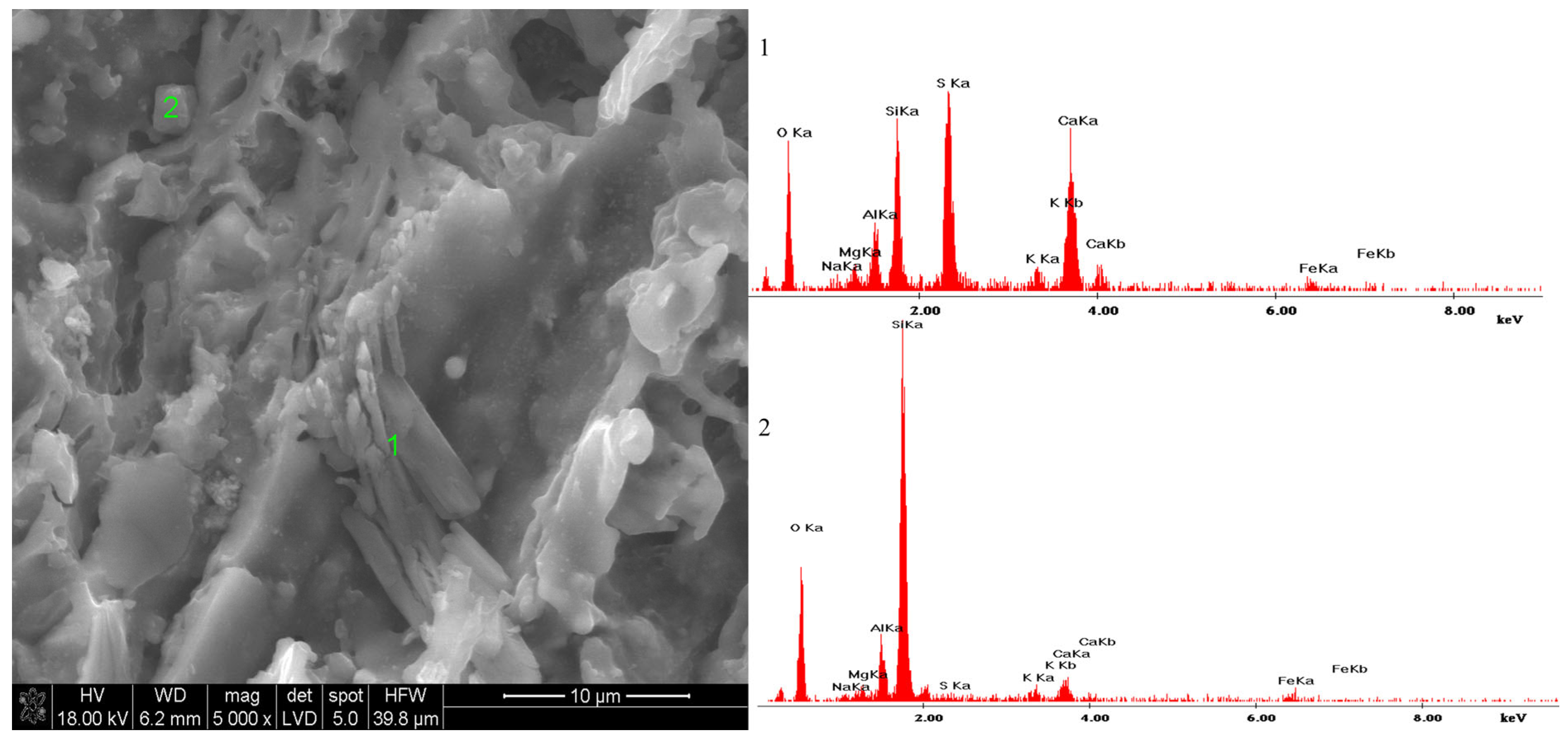
3.4. Microstructure of Materials Conditioned in Corrosive Solutions
3.5. Model Research
4. Discussion
- What role does the presence of ploweite play in the formation of glauberite, if any?
- What are the boundary conditions for the formation of the observed corrosion mechanism?
5. Conclusions
Author Contributions
Funding
Institutional Review Board Statement
Informed Consent Statement
Data Availability Statement
Conflicts of Interest
Abbreviations
| Water absorption [%] | |
| Mass of the sample saturated with water [g] | |
| Mass of sample [g] | |
| Open porosity [%] | |
| Mass of the sample saturated with water in hydrostatic conditions [g] | |
| Flexural strength [MPa] | |
| Maximum load force during flexural strength test [N] | |
| Span length [mm] | |
| Sample width [mm] | |
| Sample height [mm] | |
| Compressive strength [MPa] | |
| Breaking force during compression [N] | |
| Length of the press plate, length of the research area for compression strength [mm] | |
| Bulk density [g/cm3] | |
| Sample volume [dm3] |
References
- Brocken, H.; Nijland, T.G. White Efflorescence on Brick Masonry and Concrete Masonry Blocks, with Special Emphasis on Sulfate Efflorescence on Concrete Blocks. Constr. Build. Mater. 2004, 18, 315–323. [Google Scholar] [CrossRef]
- Koniorczyk, M.; Gawin, D. Modelling of Salt Crystallization in Building Materials with Microstructure—Poromechanical Approach. Constr. Build. Mater. 2012, 36, 860–873. [Google Scholar] [CrossRef]
- Dow, C.; Glasser, F.P. Calcium Carbonate Efflorescence on Portland Cement and Building Materials. Cem. Concr. Res. 2003, 33, 147–154. [Google Scholar] [CrossRef]
- Bensted, J. The Chemistry Efflorescence. Cem. Wapno Beton (Cem. Lime Concr.) 2001, 6, 133–142. [Google Scholar]
- La Iglesia, A.; González, V.; López-Acevedo, V.; Viedma, C. Salt Crystallization in Porous Construction Materials I Estimation of Crystallization Pressure. J. Cryst. Growth 1997, 177, 111–118. [Google Scholar] [CrossRef]
- Balboni, E.; Espinosa-Marzal, R.M.; Doehne, E.; Scherer, G.W. Can Drying and Re-Wetting of Magnesium Sulfate Salts Lead to Damage of Stone? Environ. Earth Sci. 2011, 63, 1463–1473. [Google Scholar] [CrossRef]
- Espinosa, R.M.; Franke, L.; Deckelmann, G. Phase Changes of Salts in Porous Materials: Crystallization, Hydration and Deliquescence. Constr. Build. Mater. 2008, 22, 1758–1773. [Google Scholar] [CrossRef]
- Tokarski, Z.; Wolfke, S. Corrosion of Ceramic Building Materials; Arkady: Dublin, Ireland, 1969. [Google Scholar]
- Cichoń, T.M. Influence of Bentonite Addition on the Formation of Efflorescence in Cement Mortars. Master’s Thesis, AGH University of Science and Technology, Kraków, Poland, 2008. [Google Scholar]
- Pel, L.; Huinink, H.; Kopinga, K.; Van Hees, R.P.J.; Adan, O.C.G. Efflorescence Pathway Diagram: Understanding Salt Weathering. Constr. Build. Mater. 2004, 18, 309–313. [Google Scholar] [CrossRef]
- Pietruszczak, S.; Przecherski, P.; Stryszewska, T. Impact of Salt Crystallization on the Mechanical Properties of Structural Masonry: An Experimental and Numerical Study. Constr. Build. Mater. 2022, 344, 128062. [Google Scholar] [CrossRef]
- Dubale, M.; Vasić, M.V.; Goel, G.; Kalamdhad, A.; Singh, L.B. Utilization of Construction and Demolition Mix Waste in the Fired Brick Production: The Impact on Mechanical Properties. Materials 2023, 16, 262. [Google Scholar] [CrossRef]
- Lubelli, B.; Cnudde, V.; Diaz-Goncalves, T.; Franzoni, E.; van Hees, R.P.J.; Ioannou, I.; Menendez, B.; Nunes, C.; Siedel, H.; Stefanidou, M.; et al. Towards a More Effective and Reliable Salt Crystallization Test for Porous Building Materials: State of the Art. Mater. Struct. 2018, 51, 55. [Google Scholar] [CrossRef]
- Lubelli, B.; Aguilar, A.M.; Beck, K.; De Kock, T.; Desarnaud, J.; Franzoni, E.; Gulotta, D.; Ioannou, I.; Kamat, A.; Menendez, B.; et al. A New Accelerated Salt Weathering Test by RILEM TC 271-ASC: Preliminary Round Robin Validation. Mater. Struct. 2022, 55, 238. [Google Scholar] [CrossRef]
- Lubelli, B.; Rörig-Daalgard, I.; Aguilar, A.M.; Aškrabić, M.; Beck, K.; Bläuer, C.; Cnudde, V.; D’Altri, A.M.; Derluyn, H.; Desarnaud, J.; et al. Recommendation of RILEM TC 271-ASC: New Accelerated Test Procedure for the Assessment of Resistance of Natural Stone and Fired-Clay Brick Units against Salt Crystallization. Mater. Struct. 2023, 56, 101. [Google Scholar] [CrossRef]
- Parisotto, A.; Lampert, V.; Araujo Scharnberg, A.R.; Berutti, F.A.; Alves, A.K. Colorimetric Evaluation of the Presence of Efflorescence in Red Clay Ceramics with Calcium and Sulfate Ions. Ceram. Int. 2021, 47, 16186–16191. [Google Scholar] [CrossRef]
- Anupama, V.A.; Santhanam, M. Salt Weathering Resilience in Masonry: An Accelerated Laboratory Study Involving Wind-Induced Variations. Constr. Build. Mater. 2024, 449, 138360. [Google Scholar] [CrossRef]
- Andrés, A.; Díaz, M.C.; Coz, A.; Abellán, M.J.; Viguri, J.R. Physico-Chemical Characterisation of Bricks All through the Manufacture Process in Relation to Efflorescence Salts. J. Eur. Ceram. Soc. 2009, 29, 1869–1877. [Google Scholar] [CrossRef]
- Ginchitskaia, I.; Yakovlev, G.; Kizinievich, O.; Polyanskikh, I.; Pervushin, G.; Taybakhtina, P.; Balobanova, I. Damage to Polymer Coating on Facing Brick Surface in Operated Buildings. Procedia Eng. 2017, 195, 189–196. [Google Scholar] [CrossRef]
- Chwast, J.; Todorović, J.; Janssen, H.; Elsen, J. Gypsum Efflorescence on Clay Brick Masonry: Field Survey and Literature Study. Constr. Build. Mater. 2015, 85, 57–64. [Google Scholar] [CrossRef]
- Siedel, H. Salt Efflorescence as Indicator for Sources of Damaging Salts on Historic Buildings and Monuments: A Statistical Approach. Environ. Earth Sci. 2018, 77, 572. [Google Scholar] [CrossRef]
- Matsukura, Y.; Oguchi, C.T.; Kuchitsu, N. Salt Damage to Brick Kiln Walls in Japan: Spatial and Seasonal Variation of Efflorescence and Moisture Content. Bull. Eng. Geol. Environ. 2004, 63, 167–176. [Google Scholar] [CrossRef]
- Lindström, N.; Heitmann, N.; Linnow, K.; Steiger, M. Crystallization Behavior of NaNO3-Na2SO4 Salt Mixtures in Sandstone and Comparison to Single Salt Behavior. Appl. Geochem. 2015, 63, 116–132. [Google Scholar] [CrossRef]
- Stryszewska, T.; Kańka, S. The Effects of Salt Crystallization in Ceramic Bricks in Terms of Line Deformations. Procedia Eng. 2017, 193, 120–127. [Google Scholar] [CrossRef]
- Morillas, H.; Maguregui, M.; Trebolazabala, J.; Madariaga, J.M. Nature and Origin of White Efflorescence on Bricks, Artificial Stones, and Joint Mortars of Modern Houses Evaluated by Portable Raman Spectroscopy and Laboratory Analyses. Spectrochim. Acta A Mol. Biomol. Spectrosc. 2015, 136, 1195–1203. [Google Scholar] [CrossRef] [PubMed]
- Jonaitis, B.; Marčiukaitis, G.; Valivonis, J. Analysis of the Mechanics of Carbamide Induced Destruction of Concrete and Ceramic Bricks. Constr. Build. Mater. 2013, 48, 917–924. [Google Scholar] [CrossRef]
- Morillas, H.; Maguregui, M.; Gallego-Cartagena, E.; Marcaida, I.; Carral, N.; Madariaga, J.M. The Influence of Marine Environment on the Conservation State of Built Heritage: An Overview Study. Sci. Total Environ. 2020, 745, 140899. [Google Scholar] [CrossRef] [PubMed]
- Stryszewska, T. The Change in Selected Properties of Ceramic Materials Obtained from Ceramic Brick Treated by the Sulphate and Chloride Ions. Constr. Build. Mater. 2014, 66, 268–274. [Google Scholar] [CrossRef]
- Linke, W.F.; Seidell, A. Solubilities, Inorganic and Metal-Organic Compounds, 4th ed.; American Chemical Society: Washington, DC, USA, 1958. [Google Scholar]
- Ruiz-Agudo, E.; Mees, F.; Jacobs, P.; Rodriguez-Navarro, C. The Role of Saline Solution Properties on Porous Limestone Salt Weathering by Magnesium and Sodium Sulfates. Environ. Geol. 2007, 52, 269–281. [Google Scholar] [CrossRef]
- Chekai, T.; Wijnhorst, R.; Sénéchal, P.; Grégoire, D.; Shahidzadeh, N.; Derluyn, H. Salt Weathering of Antique Dutch Ceramic Tiles. J. Cult. Herit. 2025, 72, 121–130. [Google Scholar] [CrossRef]
- Koniorczyk, M.; Konca, P. Experimental and Numerical Investigation of Sodium Sulphate Crystallization in Porous Materials. Heat Mass Transf. 2013, 49, 437–449. [Google Scholar] [CrossRef]
- Ordóñez, S.; La Iglesia, Á.; Louis, M.; García-Del-Cura, M.Á. Mineralogical Evolution of Salt over Nine Years, after Removal of Efflorescence and Saline Crusts from Elche’s Old Bridge (Spain). Constr. Build. Mater. 2016, 112, 343–354. [Google Scholar] [CrossRef]
- Liu, Z.; Li, X.N.; Deng, D.; De Schutter, G.; Hou, L. The Role of Ca(OH)2 in Sulfate Salt Weathering of Ordinary Concrete. Constr. Build. Mater. 2016, 123, 127–134. [Google Scholar] [CrossRef]
- Cardell, C.; Benavente, D.; Rodríguez-Gordillo, J. Weathering of Limestone Building Material by Mixed Sulfate Solutions. Characterization of Stone Microstructure, Reaction Products and Decay Forms. Mater. Charact. 2008, 59, 1371–1385. [Google Scholar] [CrossRef]
- Jasieńko, J.; Matkowski, Z. Zasolenie i Zawilgocenie Murów Ceglanych w Obiektach Zabytkowych—Diagnostyka, Metodyka Badań, Techniki Rehabilitacji. Wiadomości Konserw. 2003, 14, 43–48. [Google Scholar]
- Małolepszy, J.; Gawlicki, M.; Pichór, W.; Brylska, W.; Brylicki, W.; Łagosz, A.; Nocuń-Wczelik, W.; Petri, M.; Pytel, Z.; Roszczynialski, W.; et al. Podstawy Technologii Materiałów Budowlanych i Metody Badań; Wydawnictwa AGH: Kraków, Poland, 2022. [Google Scholar]
- Bednarska, D.; Koniorczyk, M. Crystallization from Sodium Sulphate Solution Confined in Red Clay Brick during Temperature Decrease. Key Eng. Mater. (KEM) 2022, 916, 123–129. [Google Scholar] [CrossRef]
- Glauberite Data. Available online: https://www.minerals.net/mineral/glauberite.aspx (accessed on 23 February 2025).


| Designation | Na | Mg | NaMg |
|---|---|---|---|
| Type and concentration | 15% Na2SO4 | 15% MgSO4 | 7.5% Na2SO4 + 7.5% MgSO4 |
| Component | SiO2 | Al2O3 | Fe2O3 | CaO | MgO | K2O | Na2O | SO3 | TiO2 | Other | Loss on Ignition |
|---|---|---|---|---|---|---|---|---|---|---|---|
| Amount [wt%] | 58.83 | 18.35 | 6.46 | 6.56 | 2.84 | 3.08 | 1.28 | 0.28 | 0.90 | 1.42 | 11.91 |
| Properties | Water Absorption Wa [%] | Open Porosity P [%] | Compressive Strength Cs [MPa] | Flexural Strength σ [MPa] | Bulk Density After Sintering ρ [g/cm3] |
|---|---|---|---|---|---|
| Value | 13.9 ± 0.2 | 24.4 ± 0.4 | 31.4 ± 1.2 | 8.6 ± 0.6 | 1.76 ± 0.05 |
| Properties | Water Absorption Wa [%] | Open Porosity P [%] | Compressive Strength Cs [MPa] | Flexural Strength σ [MPa] | Bulk Density After Sintering ρ [g/cm3] |
|---|---|---|---|---|---|
| Mg | 10.4 ± 0.2 | 19.35 ± 0.3 | 44.8 ± 1.5 | 12.5 ± 0.8 | 1.85 ± 0.04 |
| Na | 2.47 ± 0.1 | 5.07 ± 0.2 | 32.7 ± 1.0 | 9.9 ± 0.8 | 2.03 ± 0.03 |
| NaMg | break | ||||
Disclaimer/Publisher’s Note: The statements, opinions and data contained in all publications are solely those of the individual author(s) and contributor(s) and not of MDPI and/or the editor(s). MDPI and/or the editor(s) disclaim responsibility for any injury to people or property resulting from any ideas, methods, instructions or products referred to in the content. |
© 2025 by the authors. Licensee MDPI, Basel, Switzerland. This article is an open access article distributed under the terms and conditions of the Creative Commons Attribution (CC BY) license (https://creativecommons.org/licenses/by/4.0/).
Share and Cite
Wons, W.; Kłosek-Wawrzyn, E.; Rzepa, K. Corrosion of Porous Building Ceramics Caused by Double Sulphate Salt. Materials 2025, 18, 1041. https://doi.org/10.3390/ma18051041
Wons W, Kłosek-Wawrzyn E, Rzepa K. Corrosion of Porous Building Ceramics Caused by Double Sulphate Salt. Materials. 2025; 18(5):1041. https://doi.org/10.3390/ma18051041
Chicago/Turabian StyleWons, Wojciech, Ewelina Kłosek-Wawrzyn, and Karol Rzepa. 2025. "Corrosion of Porous Building Ceramics Caused by Double Sulphate Salt" Materials 18, no. 5: 1041. https://doi.org/10.3390/ma18051041
APA StyleWons, W., Kłosek-Wawrzyn, E., & Rzepa, K. (2025). Corrosion of Porous Building Ceramics Caused by Double Sulphate Salt. Materials, 18(5), 1041. https://doi.org/10.3390/ma18051041