Abstract
The significant increase in the importance of silumin recycling in the context of sustainable development is driven by tangible ecological and economic benefits. However, the primary technological challenge associated with using scrap is the accumulation of iron, which promotes the formation of undesirable sludge particles, degrading the alloy’s mechanical properties. This paper presents a description of the phase transformations in an AlSi7Mg alloy with increased iron and manganese content. Analysis of data from Differential Scanning Calorimetry (DSC) revealed the primary crystallisation of sludge particles (SP) and the pre-eutectic precipitation of the α-Al15(Fe,Mn)3Si2 phase, which replaced the β-Al5FeSi phase. The remaining constituents of the AlSi7Mg alloy structure—α(Al) solid solution dendrites, the α(Al)+β(Si) eutectic, and the Mg2Si phase—crystallise regardless of the iron, manganese, and chromium content. It was established that the increase in the crystallisation temperature of SP, rich mainly in the elements mentioned above, is directly proportional to the increase in the value of the sludge factor (SF) and ranges from 620 °C (for SF~1.3%) to approx. 645 °C (for SF~3.1%). SEM studies revealed that the combined increase in iron and manganese content not only raises the precipitation temperature of SP but also alters its morphology from single polyhedra to compact, “cluster-like” structures. To avoid the presence of sludge particles in the AlSi7Mg alloy, which have an unfavourable morphology and reduce the yield of the melting process, the SF for high-pressure die-casting should not exceed 2.0%.
1. Introduction
Due to their high strength-to-weight ratio, good castability, corrosion resistance, and recyclability, foundry aluminium alloys are frequently used in many industrial sectors, especially in the broad field of transport [1,2]. Their most common and detrimental impurity is iron [3,4]. Its impact on mechanical properties, particularly plasticity, is especially harmful when the iron content exceeds approx. 0.4 wt.% (for gravity castings) [5] and approx. 1.5 wt.% (for high-pressure die-castings) [6,7]. This occurs because iron has low solubility in the α(Al) solid solution (from 0.052% at 655 °C to 0.0051% at 450 °C) [8]. Consequently, it exhibits a strong tendency to combine with other elements, forming intermetallic phases with different stoichiometries, morphologies, and sizes [9,10]. The most undesirable phases are mainly β-Al5FeSi (β-Fe) and αH-Al8Fe2Si [11]. In Al-Si-Mg alloys with a content of 0.8 to 1.2 wt.% Mg, besides the Mg2Si phase, there is a high probability of crystallisation of the Al9Fe2Si phase with a monoclinic structure and the hexagonal Al8FeMg3Si2 phase. Additionally, metastable ternary phases β-Al4FeSi (25.4 wt.% Fe and 25.5 wt.% Si) and β-Al3FeSi (33.9 wt.% Fe and 16.9 wt.% Si) crystallise under conditions of thermodynamic non-equilibrium [8]. In Al-Si-Mg alloys with copper additions, Al2Cu, Al2CuMg, and Al6CuMg4 phases, which are in equilibrium with the α(Al) solid solution [12], as well as Al6FeCu and Al7FeCu2 phases [13], can crystallise.
Regardless of the chemical composition of aluminium alloys, the most unfavourable phase morphologically is β-Al5FeSi [14,15]. Its low coherence with the matrix and large size increase the brittleness of the alloy, complicate the machining of castings, and reduce tensile strength [14,16]. Furthermore, the plate-like/needle-like morphology of the β-Fe phase impairs the castability, ductility, and corrosion resistance of aluminium alloys. Moreover, according to studies [17,18], a large proportion of β-Fe phases contributes to an increase in shrinkage porosity, regardless of whether the porosity results from the presence of oxide films (termed “bifilms” by Campbell) [19,20] in Al-Si alloys or from the presence of β-Fe phases [5,21].
Since iron cannot be removed from liquid silumin [1], several methods have been developed to neutralise its detrimental effect on the service properties of Al-Si alloys. Examples include dilution with pure aluminium, sedimentation and filtration [22], treatment with an electromagnetic field [23], and other methods [24,25]. There are also solutions involving the introduction of so-called “chemical correctors” into liquid Al-Si(Fe) alloys, which change the unfavourable morphology of the β-Fe phase. Such additives can be strontium and phosphorus [26,27], as well as manganese, molybdenum, cobalt, and chromium [1]. Due to the similarity of the crystal lattice and lattice parameters to those of iron, these elements alter the morphology of the β-Fe phase from plate-like to so-called “Chinese script” or polyhedral blocks, thereby increasing their precipitation and making them smaller [28,29]. The best-described and most popular alloying addition is manganese [7,10], although some research indicates that chromium can be equally effective [30,31]. These additives cause the transformation of β-Al5FeSi phases into α-AlX(Fe,Mn,Cr)YSiZ-type phases (x = 12; 15; 19; 20; y = 3; 5; z = 1; 2; 3) [1], of which Al15(Fe,Mn)3Si2 or Al12(Fe,Mn)3Si2 are the most frequently formed. The Al19Fe4MnSi2 phase, considered isomorphic with Al20Fe5Si2, can also crystallise [32]. In these phases, iron, manganese, and chromium atoms can substitute for one another in the same body-centred cubic (bcc) crystal structure [33]. As reported by studies [14,34], the morphology and size of α-AlX(Fe,Mn,Cr)YSiZ-type phases vary and depend on several factors, including chemical composition, cooling rate (i.e., the degree of alloy undercooling, ΔT), and the type of technology.
However, the introduction of “chemical correctors” for the β-Fe phase, especially in an improper ratio to the iron content (recommended ratio Mn/Fe < 1), leads to the formation of undesirable sludge particles. This sediment most often consists of aluminium and magnesium oxides [10] and multi-component phases rich in iron along with aluminium, silicon, manganese, and chromium [30,35]. Since sludge has a higher density than liquid silumin, it settles at the bottom of the furnace (ladle, crucible), reducing the efficiency of the casting process. The worst scenario occurs when, for example, sediment particles enter the liquid alloy during the transfer of molten metal from the furnace to the ladle, altering its chemical composition. Then, “entrapped” in the casting, they form so-called “hard spots,” which reduce the mechanical properties, especially the ductility and castability of the alloy, and complicate the machining of castings. Furthermore, the formation of sludge particles causes a local depletion of the alloy in iron, manganese, and chromium, which increases the tendency of Al-Si alloys to hot tear onto dies [36]. For this reason, the presence of sludge particles is hazardous during high-pressure die casting, where a turbulent flow of the liquid alloy occurs. To avoid this, chemical composition limits for the sludge, defined by the so-called “sludge factor” (SF), are known [6,31]. According to [36,37], the SF should be from approx. 1.2 to 1.9%, although sometimes this range is even wider, from 0.6 to 2.85% [6]. The morphology of sludge particles depends mainly on the heat extraction rate, the chemical composition of the alloy, and especially on their crystallisation, which is why determining the precipitation temperature of sludge particles is very important, as shown by research [37,38]. However, this determination is challenging, complex, and dependent on numerous factors.
Consequently, despite numerous studies on the formation of sediment sludge and the role of sludge particles in Al-Si alloys, some aspects still require clarification. This primarily concerns the description of the crystallisation of sludge particles in Al-Si-Mn-Cr alloys with an increased iron content, as the main impurity in secondary materials, whose growing importance in the processing of aluminium alloys is evident and results from various ecological and economic aspects [39,40].
2. Materials and Methods
2.1. Aim and Scope of Research
The research aims to characterise the crystallisation process of sludge particles in a high-pressure die-cast AlSi7Mg alloy with increased iron content and additions of manganese and chromium. To achieve the adopted goal, the scope of the research includes, among others:
- performing melts of the AlSi7Mg alloy with varying shares of iron, manganese, and chromium according to the experimental plan (Figure 1),
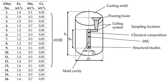 Figure 1. Research plan for the AlSi7Mg alloy with varying iron and manganese content and the location of sample collection for testing; hc—height of the casting mould: 160 mm, hp—height of the cast sample: 80 mm, ϕp—diameter of the casting mould: 60 mm, ϕc—diameter of the cast sample: 25 mm.
 - analysis of phase transformations occurring during heating and cooling using Differential Scanning Calorimetry (DSC) and determination of the range of characteristic temperatures of these transformations,
- determination of the heat of reaction (enthalpy ΔH) for AlFeMn phases and sludge particles,
- metallographic examinations.
An AlSi7Mg alloy with increased iron content was selected for the study. The choice of alloy was dictated by its good weldability, high corrosion resistance, and good mechanical properties among other Al-Si alloys. This results in its broad application, including various types of castings produced under pressure used in many industrial sectors [1,41], primarily in transportation, such as for cast automobile wheels and for 3D-printed parts with complex shapes [2].
2.2. Method of Melting Alloys
The alloy was melted from the following components and master alloys:
- aluminium grade A00 (99.9 wt.% Al),
- technical silicon with a purity of 99.6 wt.% Si,
- AlMg10 alloy (approx. 10 wt.% Mg),
- AlFe25 master alloy (approx. 25 wt.% Fe),
- AlMn50 master alloy (approx. 50 wt.% Mn), as a manganese carrier,
- AlCr10 master alloy (approx. 10 wt.% Cr), as a chromium carrier (Mn and Cr additions were introduced to change the unfavourable morphology of the β-Fe phase).
The charge materials were melted in a Balzers VSG02 induction furnace (Balzers & Co. GmbH, Bad Schönborn, Germany) in a SiC crucible with a capacity of 0.8 L. After melting the components and introducing the manganese and chromium additions (according to studies [6,31], the Mn/Fe ratio was up to 1.0, and Cr/Fe up to 0.3 [30]), the alloys were modified with an AlSr10 master alloy (0.05 wt.%) and refined with Rafglin-3 preparation (Pedmo, Tychy, Poland) in an amount of 0.2 wt.% of the alloy mass. To demonstrate only the influence of manganese, the chromium content was constant and amounted to 0.05 wt.% of the charge mass. To avoid sedimentation and ensure the homogeneity of the metallic bath, the melt was stirred regularly. Upon reaching a temperature of approx. 700 °C and taking a sample for preliminary chemical composition checking, the alloys were cast into a metal mould with a capacity of approx. 400 cm3 and a heat extraction rate (from Tliq. to Tsol.) of approx. 80–100 °C·s−1. Chemical composition measurements were performed on the top surface of the ingots, and samples for DSC calorimetric and metallographic examinations were taken from the central part of the cross-section.
2.3. Research on Structure, Phase Composition, and Phase Transformation Temperatures
Chemical composition analysis was performed using an optical emission spectrometer for quantitative elemental analysis of solid metal samples, the Foundry-Master Compact 01L00113 from Worldwide Analytical System, featuring CCD technology (SpectroLab, Kleve, Germany). For each sample, 10 measurements were performed, from which the arithmetic mean was calculated.
Investigations of phase transformations using Differential Scanning Calorimetry (DSC) were conducted on a Multi HTC Setaram high-temperature calorimeter (Mettler Toledo, Warszawa, Poland) in a 99.999% Ar (N 50) atmosphere within the temperature range of 450 to 700 °C. Cylindrical samples (weighing approx. 95 mg) were placed in an Al2O3 measurement crucible. The calorimeter was coupled with the SetSoft computer programme 1.0. Temperature (T) measurement was performed using a Pt-Rh10Pt thermocouple (Wika, Włocławek, Polska). High-purity Al2O3 powder was used as the reference substance. Before each measurement, the calorimeter was calibrated at a heating and cooling rate of 20 °C min−1 (according to the ASTM E1269 standard for determining specific heat by differential scanning calorimetry). For the AlMnFe phase and sludge particles, the area under the peak was chosen, which is proportional to the heat of reaction (enthalpy ΔH) associated with the transformation. Positive ΔH values result from the exothermic reaction of solid phase formation during solidification, and negative ones concern the enthalpy absorbed during heating of the alloy. Repeated DSC tests showed that the temperature difference during heating and cooling was ±1 °C.
Microstructure observations (Light Microscopy-LM) were performed on an Olympus GX71MeF2 light microscope (Olympus Global EMC Ltd., Tipton, UK). SEM studies were performed on a Hitachi S-3400N scanning electron microscope (Hitachi High-Technologies Tokyo, Japan), equipped with a Thermo Noran energy-dispersive X-ray spectrometer (EDS, Thermo Fisher Scientific, Waltham, MA, USA) and a Thermo MagnaRay wavelength-dispersive spectrometer (WDS), and an INCA HKL Nordys II detector for electron backscatter diffraction (EBSD) studies. Ten images were taken, of which the presented images are representative of the microstructure of the tested alloy. Samples for metallographic examination of the sediment sludge were taken from the bottom of the SiC crucible after the alloy solidified. Image acquisition of the structure and the recording process of the AlSi7Mg alloy components after the addition of iron, manganese, and chromium was performed using the AnalySis programme 12.2 using the bright-field observation method.
3. Results
3.1. Chemical Composition Test Results
The results of the chemical composition tests of the AlSi7Mg alloy with an increasing share of iron and the addition of manganese are presented in Table 1. The sludge factor was determined from the relationship: SF = (1·wt.% Fe) + (2·wt.% Mn) + (3·wt.% Cr) [6].

Table 1.
Results of the chemical composition of the AlSi7Mg alloy.
From the data presented in Table 1, it follows that the silicon content is approx. 7 wt.%, magnesium approx. 0.6 wt.%, and the assumed amounts of manganese and chromium. The remaining elements of the AlSi7Mg alloy also fall within the range given in the standard [42].
3.2. DSC Test Results
DSC tests were performed for each of the four iron contents at the minimum and maximum manganese content, i.e., for alloy numbers: 1, 4, 5, 8, 9, 12, 13, and 16. A typical heating and cooling curve obtained for AlSi7Mg alloy number 1 (1.01 wt.% Fe + 0.11 wt.% Mn) is shown in Figure 2, while that for alloy no. 12 (1.4 wt.% Fe + 0.69 wt.% Mn) is shown in Figure 3.
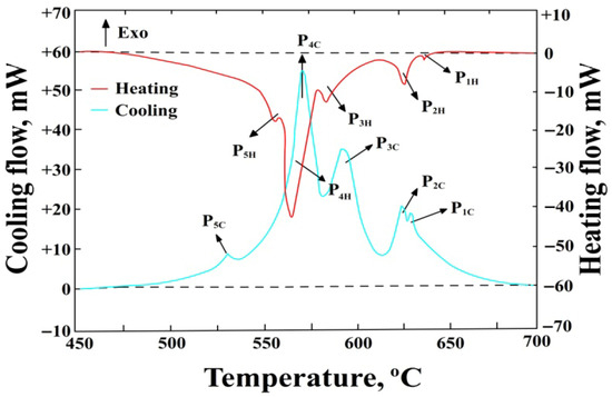
Figure 2.
DSC curve of AlSi7Mg alloy during heating and cooling (alloy number 1).
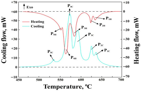
Figure 3.
DSC curve of AlSi7Mg alloy during heating and cooling (alloy number 12).
- P1H—thermal effect from the precipitation of sludge particles during heating, P1C—during cooling, mW,
- P2H—thermal effect from the precipitation of α(Al) solid solution dendrites during heating, P2C—during cooling, mW,
- P3H—thermal effect from the precipitation of AlFeMn-type phases during heating, P3C—during cooling, mW,
- P4H—thermal effect from the precipitation of the double eutectic α(Al)+β(Si) during heating, P4C—during cooling, mW,
- P5H—thermal effect from the precipitation of the eutectic containing the Mg2Si phase during heating, P5C—during cooling, mW,
- Endo—endothermic reactions,
- Exo—exothermic reactions,
- --------—baseline determining the area under the peak for calculating the enthalpy ΔH value.
A collective summary of the ranges of characteristic temperatures for the precipitation of structural constituents (during heating and cooling) for selected DSC tests is presented in Table 2.

Table 2.
Results of DSC tests during heating and cooling of the AlSi7Mg alloy for selected experiments.
Analysis of the DSC results allowed for the determination of the crystallisation sequence of the AlSi7Mg alloy. The primary phase to crystallise is sludge particles (from approx. 645 to 617 °C), with an increase in SF (Table 1) causing an increase in their precipitation temperature. Next, nucleation and crystallisation of α(Al) solid solution dendrites occur in the temperature range from approx. 628 to 617 °C-peaks P2. Their crystallisation temperature is consistent with the Al-Si equilibrium phase diagram for a content of approx. 7 wt.% Si [1]. After them, a multi-component eutectic, containing the AlFeMn-type phase, nucleates (from approx. 610 to 572 °C). An increase in the SF (Table 1) causes an increase in its crystallisation temperature, but it is always a crystallisation preceding the α(Al)+β(Si) eutectic. The next constituent of the AlSi7Mg alloy is the double eutectic α(Al)+β(Si), which crystallises from approx. 568 to 559 °C (peaks P4). The range of its crystallisation temperature is also consistent with the Al-Si equilibrium phase diagram and slightly lower than the temperature under equilibrium conditions (577 °C) [1,2]. Towards the end of its crystallisation, the Mg2Si phase nucleates and precipitates, being a constituent of the α(Al)+Mg2Si+β(Si) eutectic (from 554 to 540 °C), which is simultaneously the end of solidification of the AlSi7Mg alloy. Thus, the temperature ranges for the crystallisation of the α(Al) solid solution dendrites, the double α(Al)+β(Si) eutectic, and the triple α(Al)+Mg2Si+β(Si) eutectic are typical for the AlSi7Mg alloy, as confirmed in studies [43,44].
The primary reaction of sludge particles (before the formation of the α(Al) solid solution dendrites) deserves attention. From the DSC curves, it follows that as the SF value increases, the crystallisation of sludge particles not only occurs at a higher temperature but also the peak area associated with their precipitation becomes larger. This is related to the increasing value of heat released (during heating—an exothermic reaction) and absorbed (during cooling—an endothermic reaction) by the AlSi7Mg alloy. A similar regularity was observed for AlFeMn-type phases, meaning that an increase in the SF value is accompanied by an increase in crystallisation temperature (from 572 to 610 °C) and the area of the peaks associated with their precipitation. Therefore, measurements of enthalpy ΔH were performed during heating (+) and cooling (−), and a collective summary of these results is presented in Table 3.

Table 3.
Value of enthalpy ΔH of precipitation of sludge particles and AlFeMn-type phases during heating and cooling of the AlSi7Mg alloy for selected experiments.
To identify the phases whose reactions were recorded on the DSC curves, microstructure examinations of the AlSi7Mg alloy were performed.
3.3. Microstructure Test Results
Representative microstructures (SEM) of the AlSi7Mg alloy after the introduction of iron, manganese, and chromium are shown in Figure 4.

Figure 4.
SEM microstructure of the AlSi7Mg alloy: (a) alloy no. 1 (SF = 1.37%); (b) alloy no. 6 (SF = 1.98%); (c) alloy no. 10 (SF = 2.14%).
From the microstructure identification and the authors’ own research [44], it follows that in the AlSi7Mg alloy, besides structural constituents—such as α(Al) dendrites; β(Si) crystals (part of the α(Al)+β(Si) eutectic); and the Mg2Si phase—part of the α(Al)+Mg2Si+β(Si) eutectic, the α-Al15(Fe;Mn)3Si2 phase, scarce precipitates of the β-Al5FeSi (β-Fe) and α-Al13(Fe;Cr)4Si4 [45] phases, and sludge particles were identified. From the microstructures presented in Figure 4, it follows that if SF < 1.5%, the microstructure of the AlSi7Mg alloy with an elevated share of iron and manganese is correct, and the (β-Fe) phases have been replaced by α-Al15(Fe;Mn)3Si2 with a typical dendritic structure. Increasing the SF from 1.5 to approx. 2.0% causes the appearance of scarce β-Fe precipitates, and the arms of the α-Al15(Fe;Mn)3Si2 phase become “thicker” (Figure 4b). If the sludge factor exceeds approx. 2.0%, then in the structure of the tested alloy, besides β-Fe and α-Al15(Fe;Mn)3Si2 phase precipitates, individual, “blocky” precipitates of sludge particles appear (Figure 4c). The microstructure of the AlSi7Mg alloy without sludge particles and with sludge particles is shown in Figure 5, and the surface distribution of aluminium, manganese, and iron in the sludge particles is shown in Figure 6.
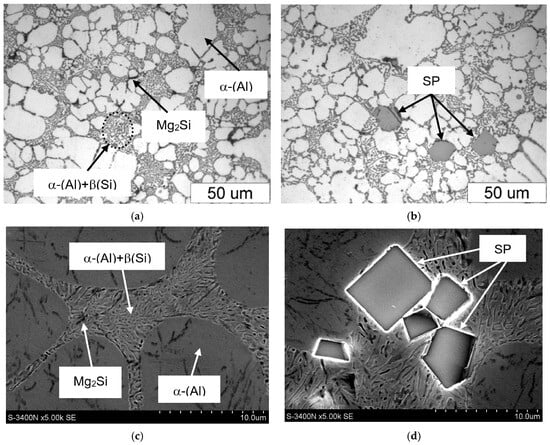
Figure 5.
Microstructure of the AlSi7Mg alloy: (a,c) alloy no. 1 (without sludge particles); (b,d) alloy no. 11 (presence of sludge particles); (a,b) LM; (c,d) SEM.
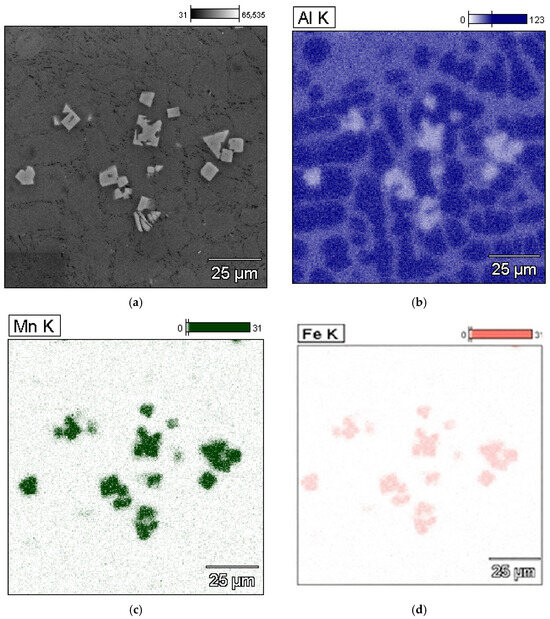
Figure 6.
Microstructure (SEM) of the AlSi7Mg alloy containing sludge particles (a) and surface distribution of elements: (b) aluminium; (c) manganese; (d) iron.
The microstructure containing sludge particles and the results of microanalysis of the chemical composition of the AlSi7Mg alloy are presented in Figure 7.
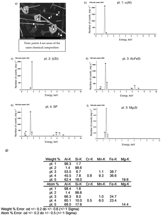
Figure 7.
Microstructure (SEM) of the AlSi7Mg alloy containing sludge particles (a) and results of microanalysis of the chemical composition: (b) α(Al) dendrites, (c) β(Si) crystals, (d) Al5FeSi phase, (e) sludge particles, (f) Mg2Si phase, (g) element content at the investigated points.
To identify the structural constituents and intermetallic phases revealed in the microstructure of the AlSi7Mg alloy after introducing the Al-Mn master alloy, XRD investigations were carried out. The X-ray diffraction results are presented in Figure 8.
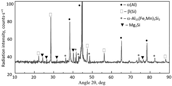
Figure 8.
XRD diffraction pattern of AlSi7Mg alloy with manganese addition (sample no. 3).
Based on microscopic examinations, it can be stated that the structure of the AlSi7Mg alloy is correct. It corresponds to hypoeutectic Al-Si-Mg alloys with an increased content of iron and manganese. These elements (along with chromium) form sludge particles. Their morphology (similar to the Al15(Fe;Mn)3Si2 phase) changes with an increase in the SF value. Individual polyhedra “agglomerate” to form more massive clusters, as shown in Figure 9. However, explaining this phenomenon requires additional research.
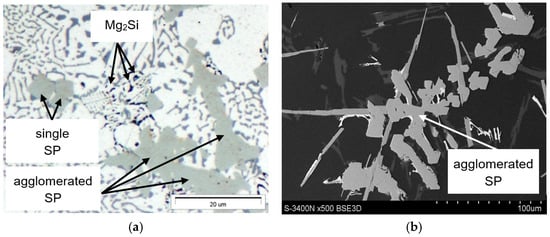
Figure 9.
Microstructure (a) LM and (b) SEM of the AlSi7Mg alloy showing the varying morphology of sludge particles: (a) magnification 1000×; (b) magnification 500×.
It should therefore be noted that an increase in iron and manganese content affects not only the change in morphology of the Al15(Fe;Mn)3Si2 phase (from typically dendritic to more “fluffy”) but also the change in the structure of sludge particles from individual polyhedra (appearing as polygons on the polished surface) to compact “cluster-like” structures.
4. Discussion
The research aimed to identify phase transformations during the heating and cooling of an AlSi7Mg alloy with increased iron and manganese content using Differential Scanning Calorimetry (DSC) and to characterise the constituents of the alloy’s microstructure, with particular emphasis on so-called sludge particles (SP).
As research suggests [46], identifying phase transformations related to the crystallisation of intermetallic phases containing iron and manganese is difficult due to the influence of many factors, particularly the cooling rate and chemical composition. The method best suited for this is Differential Scanning Calorimetry (DSC).
From the DSC studies, it follows that the crystallisation of the AlSi7Mg alloy with increased iron and manganese content (at constant chromium content) proceeds according to the following sequence:
where the eutectics (E) may crystallise simultaneously.
Liq. → SP + α(Al) + Al15(Fe,Mn)3Si2 + [α(Al) + β(Si)]E + [α(Al) + (Mg2Si) + β(Si)]E
The DSC investigation revealed that the crystallisation of the α(Al) dendrites occurs within the temperature range of approximately 618 °C to 626 °C (Table 2). Research [46] found that this range is between 588 and 593 °C in an AlSi9Cu3(Fe) alloy without manganese and between 594 and 604 °C with manganese. However, it is worth noting that the studied alloy had a higher silicon content (9 wt.%), which is consistent with the Al-Si equilibrium phase diagram. Furthermore, the AlSi9Cu3 alloy contains between 0.03 and 2.30 wt.% Cu, and as indicated by studies [46], copper lowers the crystallisation temperature of the α(Al) dendrites.
The temperature ranges for the crystallisation of AlFeMn-type phases and the α(Al)+β(Si) eutectic are also consistent with the results of the study [46]. The authors of the manuscript [46] also note that slight differences in temperatures for individual DSC measurements (up to approx. 15 °C) may occur, resulting from the cooling rate and chemical composition. As evidenced by research [47], the accurate analysis of phase transformations is most precise when samples are heated and cooled slowly at rates up to 20 °C min−1 (as was performed in the present manuscript). Higher rates can cause thermal effects to “overlap,” leading to misinterpretation of the DSC results.
The enthalpy during the formation of AlFeMn-type phases ranges from approx. 18 to 30 J·g−1 (Table 3) and is similar to the results of study [48], although potential differences in ΔH values may stem from varying iron and manganese contents and differences in the stoichiometry of these phases. The type of heat treatment applied is also significant. The results of the study [49] indicate that despite similar alloys (AlSi10Mg0.3Mn and 319), differences in ΔH values can amount to several J·g−1. Table 3 also shows that the enthalpy of the sludge particles ranges from approx. 5 to 12 J·g−1. Although these particles have been identified in numerous different works [36,41], the corresponding ΔH values are not provided therein, making it difficult to relate the obtained results to other studies.
The temperature ranges of crystallisation of the main structural constituents of the tested alloy are consistent with the results of works [1,2] and the sequence of crystallising phases as observed in studies [5,8]. The addition of manganese causes the transformation of plate-like/needle-like precipitates of the β-Al5FeSi phase into the α-Al15(Fe,Mn)3Si2 phase, characterised by a dendritic morphology (sometimes referred to as “Chinese script”). The presence of the α(Al)+Mg2Si+β(Si) eutectic containing the Mg2Si phase was confirmed. The research indicates that this eutectic forms at the end of the solidification of the AlSi7Mg alloy (approx. 554 to 540 °C). In Al-Si-Mg alloys with high iron and manganese content, it is not a constituent of sludge particles (Figure 7) and does not influence their morphology. This is confirmed by the results of studies [13,28].
Microstructure examinations of the AlSi7Mg alloy with elevated iron and manganese content also revealed the presence of sludge particles (SP). It was found that if the sludge factor [6] is up to approx. 1.5% (for high-pressure die-casting), the plate-like precipitates of the β-Fe phases are replaced by α-Al15(Fe;Mn)3Si2, which has a typical dendritic structure. Increasing the sludge factor from 1.5 to approx. 2.0% causes the appearance of scarce β-Fe precipitates (with lengths from 150 to 250 μm), and the arms of the Al15(Fe;Mn)3Si2 phase become thicker (Figure 4b,c). No additional AlFeMn-type phases were found in the structure of the AlSi7Mg alloy, only the rarely occurring Al13(Fe;Cr)4Si4 phase. When the sludge factor exceeds approx. 2.0%, in the structure of the tested alloy, besides β-Fe and Al15(Fe;Mn)3Si2 phases, sludge particles appear in the form of individual polygons (Figure 5d and Figure 7). Increasing iron and manganese content (SF > 2.7%) causes the arms of the Al15(Fe;Mn)3Si2 phase to become even “thicker,” and the sludge particles (rich in these elements) “agglomerate,” forming more massive clusters (Figure 8). This is probably because the “excess” iron and manganese atoms, which were not “bound” in the form of the Al15(Fe;Mn)3Si2 phase, formed the primarily crystallising sludge particles, settling at the bottom of the crucible (ladle), reducing the yield of the casting process. These observations are consistent with the results of studies [6,36]. Furthermore, it was found that the increase in the crystallisation temperature of sludge particles is directly proportional to the increase in the value of the sludge factor: from 620 °C (for SF~1.3%) to approx. 645 °C (for SF~3.1%) (Table 1 and Table 2). Hence, it can be stated that the crystallisation temperature of particles constituting the sediment sludge depends on the SF value, and therefore on the combined content of iron, manganese, and chromium. This is consistent with the sludge factor equation [33,36] and the results of studies [6,32], which present so-called “segregation curves” indicating critical values for preventing sediment formation.
Despite numerous studies on sludge particles [36,41], the literature lacks a quantitative assessment of the morphology of these particles. An exception is the research [6] concerning the AlSi9Cu3(Fe) alloy. It shows that an increase in iron and manganese content causes a linear increase in the average surface area and number of sludge particles. At the same time, the addition of chromium has no effect. The microstructure results of the AlSi7Mg alloy (Figure 4 and Figure 8) confirm these trends, although a quantitative analysis of the distribution of these particles was not performed. This will be the subject of further research on the microstructure of sludge particles in Al-Si alloys obtained from secondary materials.
Furthermore, the authors of the study [6] indicate that to better understand the morphology and distribution of sludge particles in Al-Si alloys, FEG-SEM studies after deep etching are necessary. This would allow for better revelation of the interior of both AlFeMn-type phases and sludge particles, which exhibit a structure of rhombic dodecahedra with empty spaces inside [6].
Although attempts to identify factors influencing the morphology of sludge particles can be found, for example, in studies [36,41], many issues regarding the crystallisation mode of these particles remain unclear. This concerns, for example, their nucleation mechanism [5,19], type of technology [25,41], cooling rate [4,33], and influence on the service properties of aluminium alloys produced from secondary components. These discrepancies underscore the need for further research in this area.
5. Conclusions
The following conclusions have been formulated based on the research conducted:
- DSC tests revealed the primary crystallisation of sludge particles (SP), which, due to their weight, settle at the bottom of the crucible (ladle), reducing the casting process yield and are essential in controlling the microstructure of the AlSi7Mg(Fe) alloy.
- The increase in the crystallisation temperature of SP, rich mainly in iron, manganese, and chromium, is directly proportional to the increase in the value of the sludge factor (SF) and ranges from 620 °C (for SF~1.3%) to approx. 645 °C (for SF~3.1%).
- The combined increase in iron and manganese content influences not only the increase in the precipitation temperature of SP but also the change in their morphology from individual polyhedra (appearing as polygons on the polished surface) to compact “cluster-like” structures.
- To avoid the formation of sludge particles with an unfavourable structure in high-pressure die-castings made of AlSi7Mg alloy, the SF should not exceed 2.0%.
- DSC tests revealed the pre-eutectic crystallisation of the α-Al15(Fe;Mn)3Si2 phase, whose morphology depends on the combined content of iron, manganese, and chromium. For SF < 1.5%, the microstructure of the AlSi7Mg alloy with an elevated share of iron and manganese contains the α-Al15(Fe;Mn)3Si2 phase with a typical dendritic structure. A higher SF value leads to a significant thickening of the arms of the α phase.
- The Mg2Si phase identified in the AlSi7Mg alloy (crystallising last) is not a constituent of sludge particles and does not influence their morphology.
Author Contributions
Conceptualization, J.P.; Methodology, S.R.; Software, S.R.; Validation, S.S.; Formal analysis, S.S.; Investigation, J.P., S.R. and M.G.; Resources, J.P.; Data curation, S.R. and S.S.; Writing—original draft, S.S.; Writing—review & editing, M.G.; Visualization, S.R.; Supervision, M.G.; Project administration, J.P.; Funding acquisition, J.P. All authors have read and agreed to the published version of the manuscript.
Funding
This research received no external funding.
Data Availability Statement
The original contributions presented in this study are included in the article. Further inquiries can be directed to the corresponding author.
Conflicts of Interest
The authors declare no conflict of interest.
References
- Kammer, C. Aluminium Handbook. Vol. 1: Fundamentals and Materials; Beuth Verlag GmbH: Berlin, Germany, 2011. [Google Scholar]
- King, F. Aluminum and its Alloys; Ellis Horwood: Chichester, UK; John Wiley & Sons: New York, NY, USA, 1987. [Google Scholar]
- Mbuya, T.O.; Odera, B.; Ng’ang’a, S. Influence of Iron on Castability and Properties of Al-Si Alloys: Literature Review. Int. J. Cast Met. Res. 2003, 16, 451–465. [Google Scholar] [CrossRef]
- Davis, J.R. Aluminum and Aluminum Alloys ASM Specialty Handbook; ASM International: Materials Park, OH, USA, 1993. [Google Scholar]
- Taylor, J.A. Iron-Containing Intermetallic Phases in Al-Si Based Casting Alloys. Procedia Mater. Sci. 2012, 1, 19–33. [Google Scholar] [CrossRef]
- Ferraro, S.; Fabrizi, A.; Timelli, G. Evolution of sludge particles in secondary die-cast aluminium alloys as function of Fe, Mn and Cr contents. Mater. Chem. Phys. 2015, 153, 168–179. [Google Scholar] [CrossRef]
- Seifedine, S.; Svensson, I.L. The influence of Fe and Mn content and cooling rate on the microstructure and mechanical properties of A380-die casting alloys. Metall. Sci. Technol. 2009, 27, 11–20. [Google Scholar]
- Belov, N.A.; Aksenov, A.A.; Eskin, D.G. Iron in Aluminum Alloys. Impurity and Alloying Element; Taylor & Francis Inc: New York, NY, USA, 2002. [Google Scholar] [CrossRef]
- Ebhota, W.S.; Tien-Chien, J. Intermetallics Formation and Their Effect on Mechanical Properties of Al-Si-X Alloys; IntechOpen: London, UK, 2014. [Google Scholar] [CrossRef]
- Shabestari, S.G. The effect of iron and manganese on the formation of intermetallic compounds in Al-Si alloys. Mater. Sci. Eng. A 2004, 383, 289–298. [Google Scholar] [CrossRef]
- Moustafa, M.A. Effect of iron content on the formation of β-Al5FeSi and porosity in Al-Si eutectic alloys. J. Mater. Process. Technol. 2009, 209, 605–610. [Google Scholar] [CrossRef]
- Liu, G.; Gong, M.; Xie, D.; Wang, J. Structures and mechanical properties of Al-Al2Cu interfaces. J. Miner. Met. Mater. Soc. 2019, 71, 1200–1208. [Google Scholar] [CrossRef]
- Gaber, A.; Gaffar, M.A.; Mostafa, M.S.; Essam, A.Z. Precipitation kinetics of Al–1.12Mg2Si–0.35 Si and Al–1.07 Mg2Si–0.33Cu alloys. J. Alloys Compd. 2007, 429, 167–175. [Google Scholar] [CrossRef]
- Cao, X.; Campbell, J. Morphology of β-Al5FeSi phase in Al-Si cast alloys. Mater. Trans. 2006, 47, 1303–1312. [Google Scholar] [CrossRef]
- Mahta, M.; Emamy, M.; Cao, X.; Campbell, J. Overview of β-Al5FeSi phase in Al-Si cast alloys. In Materials Science Research Trends; Nova Science Publishers, Inc.: Hauppauge, NY, USA, 2008. [Google Scholar]
- Cais, J.; Weiss, V.; Svobodova, J. Relation Between Porosity and Mechanical Properties of Al-Si Alloys Produced by Low-Pressure Casting; Archives of Foundry Engineering: Krakow, Poland, 2014; Volume 14, pp. 97–102. Available online: https://yadda.icm.edu.pl/baztech/element/bwmeta1.element.baztech-e333b27c-9532-4dc4-ab73-64260703c143 (accessed on 23 October 2025).
- Lu, L.; Dahle, A.K. Iron-Rich Intermetallic Phases and Their Role in Casting Defect Formation in Hypoeutectic Al-Si Alloys. Metall. Mater. Trans. 2005, 36, 819–835. [Google Scholar] [CrossRef]
- Dinnis, C.M.; Taylor, J.A.; Dahle, A.K. Porosity Formation and Eutectic Growth in Al-Si-Cu-Mg Alloys Containing Iron and Manganese. In Proceedings of the 9th International Conference on Aluminium Alloys 2004, Queensland, Australia, 2-5 August 2004; Nie, J.F., Morton, A.J., Muddle, B.C., Eds.; The University of Queensland: Queensland, Australia, 2004; Available online: http://www.icaa-conference.net/ICAA9/data/papers/GP%20149.pdf (accessed on 23 October 2025).
- Campbell, J. Metal Casting Processes, Metallurgy, Techniques and Design. In Complete Casting Handbook, 2nd ed.; Elsevier: Amsterdam, The Netherlands, 2015. [Google Scholar]
- Park, J.M. Behaviours of Bifilms in A356 Alloy During Solidification: Developing Observation Techniques with 3-D Micro X-Ray Tomography; School of Metallurgy and Materials College of Engineering, The University of Birmingham: Birmingham, UK, 2009. [Google Scholar]
- Piątkowski, J.; Roskosz, S.; Stach, S. The Influence of Selected High–Pressure Die Casting Parameters on the Porosity of EN AB-46000 Alloy Castings. Adv. Sci. Technol. Res. J. 2024, 18, 361–371. [Google Scholar] [CrossRef]
- Lopes de Mores, H.; Roberto de Oliveira, J.; Crocce Espinosa, D.; Tenario, J. Removal of iron from molten recycled aluminum through intermediate phase filtration. Mater. Trans. 2006, 47, 1731–1736. [Google Scholar] [CrossRef]
- Osawa, Y.; Takamori, S.; Kimura, T.; Minagawa, K.; Kakisawa, H. Morphology of intermetallic compounds in Al-Si-Fe alloy and its control by ultrasonic vibration. Mater. Trans. 2007, 48, 2467–2475. [Google Scholar] [CrossRef]
- Dai, H.S.; Xiangfa, L. Refinement performance and mechanism of an Al-50Si alloy. Mater. Charact. 2008, 59, 1559–1569. [Google Scholar] [CrossRef]
- Shabestari, S.G.; Gruzleski, J.E. Gravity segregation of complex intermetallic compounds in liquid Al-Si alloys. Metall. Mater. Trans. A 1995, 26, 999–1006. [Google Scholar] [CrossRef]
- Chai, G.C.; Bâckerud, L. Factors affecting modification of Al-Si alloys by addition of strontium-containing master alloys. AFS Trans. 1992, 100, 847–854. [Google Scholar]
- Pennors, A.; Samuel, A.M.; Samuel, F.H.; Doty, H.W. Precipitation of β-Al5FeSi iron intermetallic in Al-6%Si-3.5%Cu (319) type alloys: Role of Sr and P. AFS Trans. 1998, 106, 251–264. [Google Scholar]
- Ma, Z.; Samuel, A.M.; Samuel, F.H.; Doty, H.W.; Valtierra, S. A study of tensile properties in Al-Si-Cu and Al-Si-Mg alloys: Effect of β-iron intermetallics and porosity. Mater. Sci. Eng. 2008, 490, 36–51. [Google Scholar] [CrossRef]
- Shabestari, S.G.; Keshavarz, M.; Hejazi, M.M. Effect of strontium on the kinetics of formation and segregation of intermetallic compounds in A380 alloy. J. Alloys Compd. 2009, 477, 892–899. [Google Scholar] [CrossRef]
- Gustafsson, G.; Thorvaldsson, T.; Dunlop, G.L. The influence of Fe and Cr on the microstructure of cast Al-Si-Mg alloys. Metall. Trans. A 1986, 17, 45–52. [Google Scholar] [CrossRef]
- Timelli, G.; Bonollo, F. The influence of Cr content on the microstructure and mechanical properties of AlSi9Cu3(Fe) die-casting alloys. Mater. Sci. Eng. 2010, 528, 273–282. [Google Scholar] [CrossRef]
- Cooper, M.; Robinson, K. The crystal structure of the ternary alloy α(AlMnSi). Acta Crystallogr. 1996, 20, 614–617. [Google Scholar] [CrossRef]
- Alexander, D.T.L.; Greer, A.L. Solid state intermetallic phase transformations in 3XXX aluminium alloys. Acta Mater. 2002, 50, 2571–2583. [Google Scholar] [CrossRef]
- Kaja, S.S.T.; Gangadasari, P.R.; Ayyagari, K.P.R. Extending the Tolerance of Iron in Cast Al-Si Alloy. JOM 2021, 73, 2652–2657. [Google Scholar] [CrossRef]
- Seifeddine, S.; Johansson, S.; Svensson, I.L. The influence of cooling rate and manganese content on the Al5FeSi phase formation and mechanical properties of Al-Si-based alloys. Mater. Sci. Eng. 2008, 490, 385–390. [Google Scholar] [CrossRef]
- Timelli, G.; Capuzzi, S.; Fabrizi, A. Precipitation of primary Fe-rich compound in secondary AlSi9Cu3(Fe) alloys. J. Therm. Anal. Calorim. 2016, 123, 249–262. [Google Scholar] [CrossRef]
- Wang, L.; Makhlouf, M.M.; Apelian, D. Aluminium die casting alloys: Alloy composition, microstructure, and properties-performance relationships. Int. Mater. Rev. 1995, 40, 221–238. [Google Scholar] [CrossRef]
- Flores, A.; Sukiennik, M.; Castillejos, A.H.; Acosta, F.A.J.; Escobedo, C. A kinetic study on the nucleation and growth of the Al8FeMnSi2 intermetallic compound for aluminum scrap purification. Intermetallics 1998, 6, 217–227. [Google Scholar] [CrossRef]
- Metal Recycling Factsheet. Europe Aluminum Market Overview 2024–2028. Available online: https://circulareconomy.europa.eu/platform/sites/default/files/euric_metal_recycling_factsheet.pdf (accessed on 1 August 2025).
- Passarini, F.; Ciacci, L.; Nuss, P.; Manfredi, S. Material Flow Analysis of Aluminium, Copper and Iron in the EU-28. JRC Technical Reports 2018 European Commission. Available online: https://publications.jrc.ec.europa.eu/repository/bitstream/JRC111643/jrc111643_mfa_final_report_june2018.pdf (accessed on 1 August 2025).
- Bösch, D.; Pogatscher, S.; Hummel, M.; Fragner, W.; Uggowitzer, P.J.; Göken, M.; Höppel, H.W. Secondary Al-Si-Mg high-pressure die casting alloys with enhanced ductility. Metall. Mater. Trans. 2014, 46, 1035–1045. [Google Scholar] [CrossRef]
- EN 1706-2010; Aluminium and Aluminium Alloys–Castings–Chemical composition and Mechanical Properties. European Committee for Standardization (CEN): Brussels, Belgium, 2020.
- Piątkowski, J. Crystallization of Casting Aluminum Alloys; Publishing Archives of Foundry Engineering: Katowice-Gliwice, Poland, 2021; ISBN 978-83-63605-49-0. [Google Scholar]
- Piątkowski, J.; Chowaniec, L.; Matuła, T. Application of thermal-derivative analysis to study phase transformation in AlSi7Mg alloy with different iron content. Mach. Technol. Mater. 2025, 19, 110–113. [Google Scholar]
- Piątkowski, J.; Chowaniec, L.; Matuła, T.; Reyna, M.; Sanchez, G. Effect of chromium on the microstructure of AlSi7Mg alloy with increased iron content. Non-Equilibrium Phase Transformations. Mater. Sci. 2025, 11, 3–33. [Google Scholar]
- Schoß, J.P.; Schramm, E.; Schönherr, P.; Mrówka, N.M.; Schumann, H.; Becker, H.; Keßler, A.; Szucki, M.; Wolf, G. Investigation of the Formation of Iron-Rich Intermetallic Phases in Al–Si Alloys via Thermal Analysis Cooling Curves, Including a Real-Time Detection for Filtration Process. Adv. Eng. Mater. 2023, 25, 2201576. [Google Scholar] [CrossRef]
- Abdulrahman, K.M.; Gonda, V.; Réger, M. Differential scanning calorimetry of aluminium EN AB-42000 alloy rheocasting semi-solid in different stage heating rates. Innov. Infrastruct. Solut. 2023, 8, 293. [Google Scholar] [CrossRef]
- Warmuzek, M. Analysis of the chemical composition of AlMnFe and AlFeMnSi intermetallic phases in the interdendritic eutectics in the Al-alloys. Trans. Foundry Res. Inst. 2014, 54, 3–12. [Google Scholar] [CrossRef]
- Chen, Z.; Liu, K.; Elgallad, E.; Breton, F.; Chen, X.-G. Differential Scanning Calorimetry Fingerprints of Various Heat-Treatment Tempers of Different Aluminum Alloys. Metals 2020, 10, 763. [Google Scholar] [CrossRef]
Disclaimer/Publisher’s Note: The statements, opinions and data contained in all publications are solely those of the individual author(s) and contributor(s) and not of MDPI and/or the editor(s). MDPI and/or the editor(s) disclaim responsibility for any injury to people or property resulting from any ideas, methods, instructions or products referred to in the content. |
© 2025 by the authors. Licensee MDPI, Basel, Switzerland. This article is an open access article distributed under the terms and conditions of the Creative Commons Attribution (CC BY) license (https://creativecommons.org/licenses/by/4.0/).