
Enhancing Reciprocating Wear Resistance of Co37Cr28Ni31Al2Ti2 Spark Plasma Sintered Medium-Entropy Alloy via TiC Addition


Abstract
1. Introduction
2. Materials and Methods
2.1. Materials Preparation
2.2. Microstructure Characterization
2.3. Mechanical Properties
3. Results and Discussion
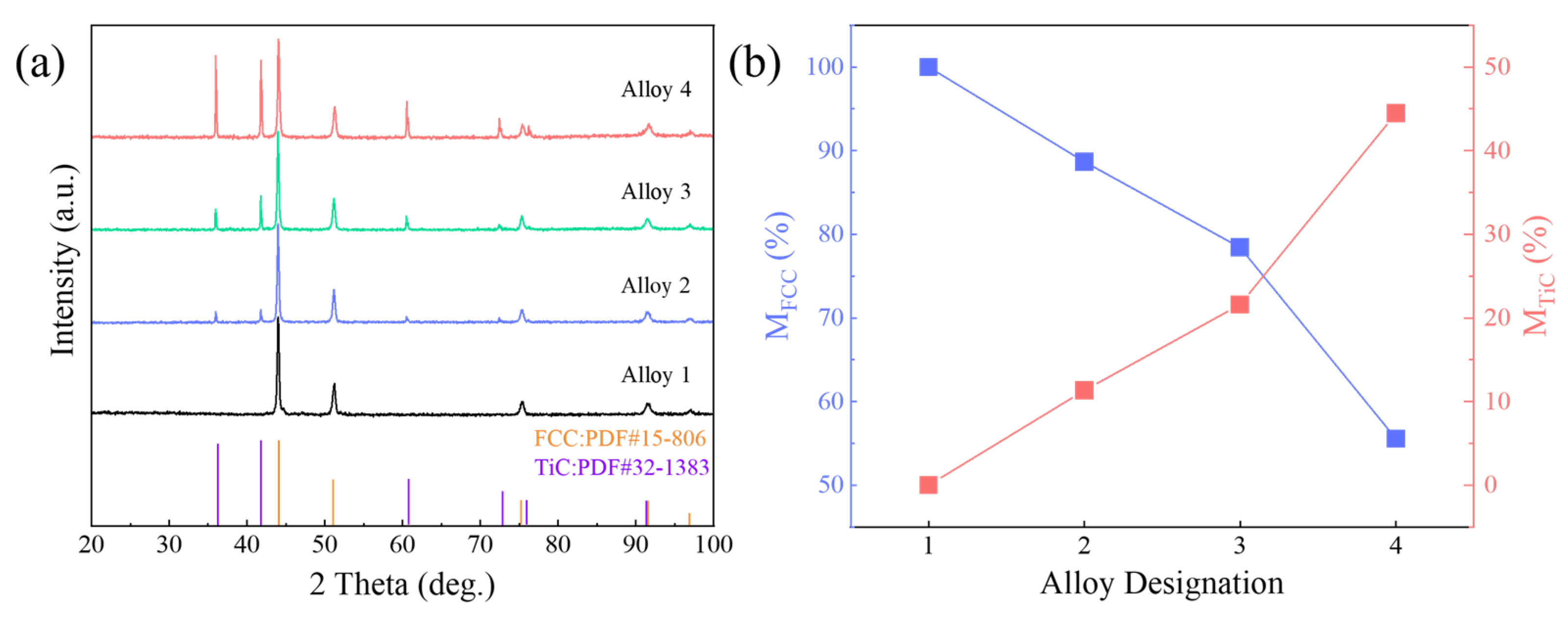
3.1. XRD Analysis
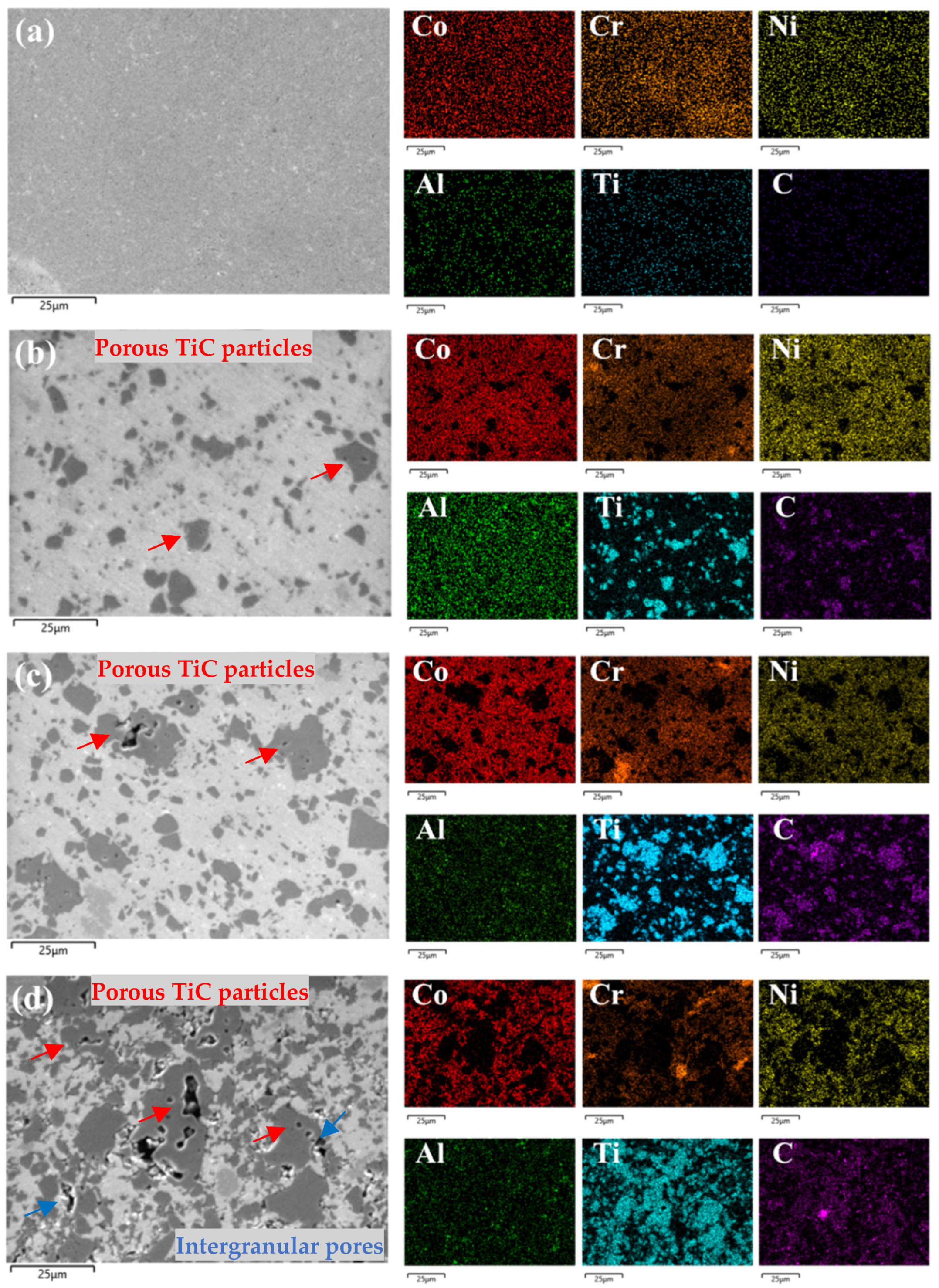
3.2. Microstructure
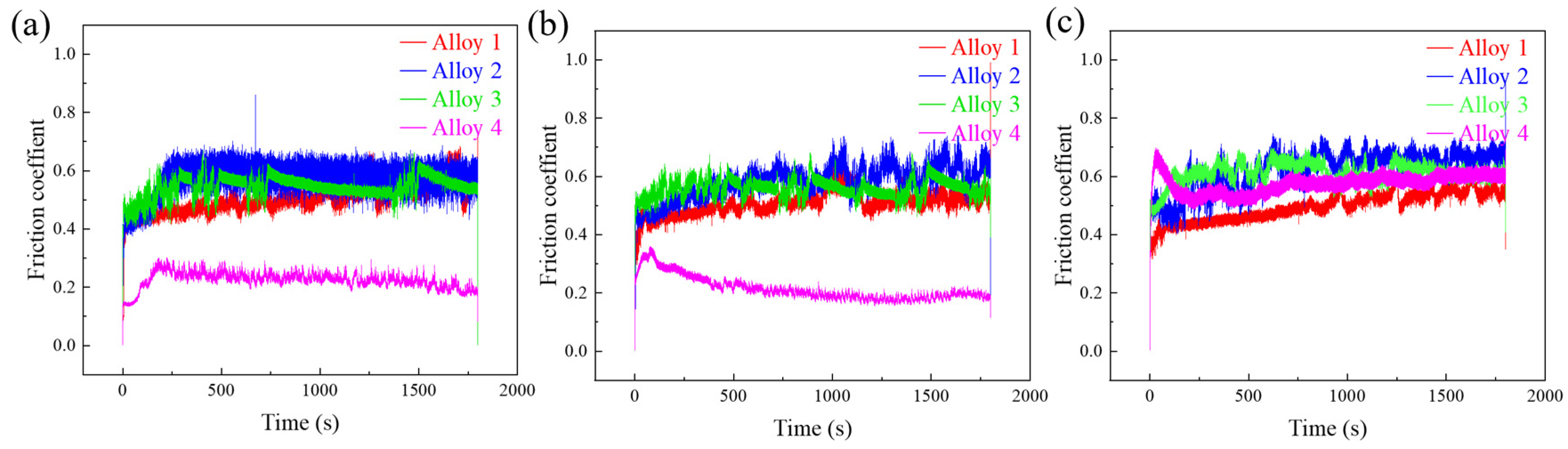
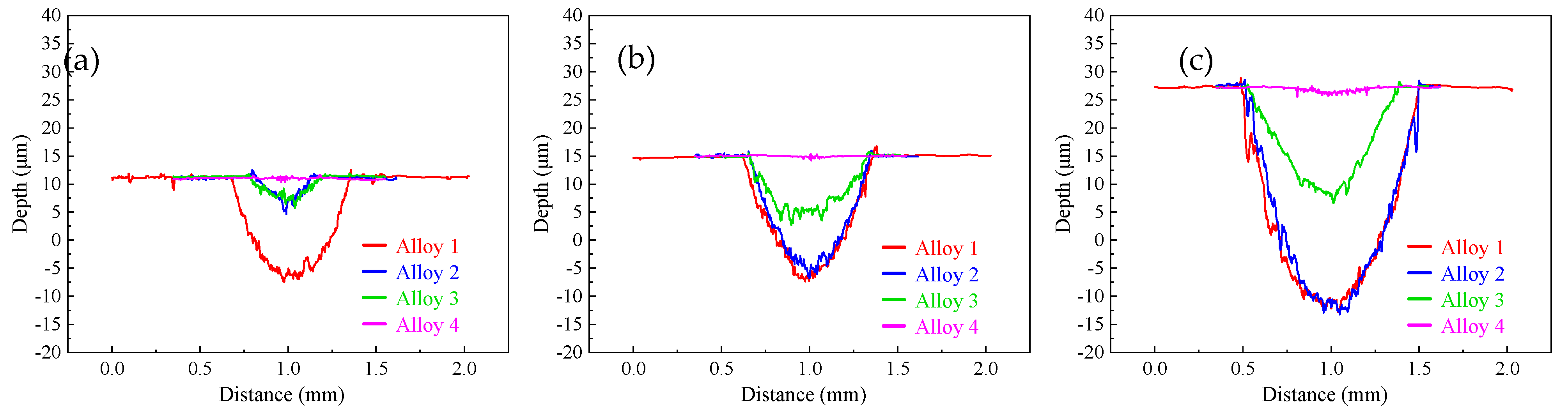
3.3. Hardness and Wear Resistance
4. Conclusions
- The medium-entropy alloy samples were well-sintered with a uniform structure. In the matrix of the alloy containing TiC, agglomerated carbides appear. As the TiC content increases, the carbide in the alloy changes from uniform particle distribution with no porosity to later carbide agglomeration with increased porosity. The major part of porosity is formed by internal voids inside TiC grains, and a minor part of it is located on the TiC-MEA interphase. The performed research proves the strong positive effect of TiC addition on the wear resistance of Co37Cr28Ni31Al2Ti2 MEA.
- The hardness of the basic alloy is 439 HV, which increases to 473 HV with 10% TiC, 503 HV with 20% TiC, and 623 HV with 40% TiC. The addition of TiC particles significantly enhances the hardness of the alloy.
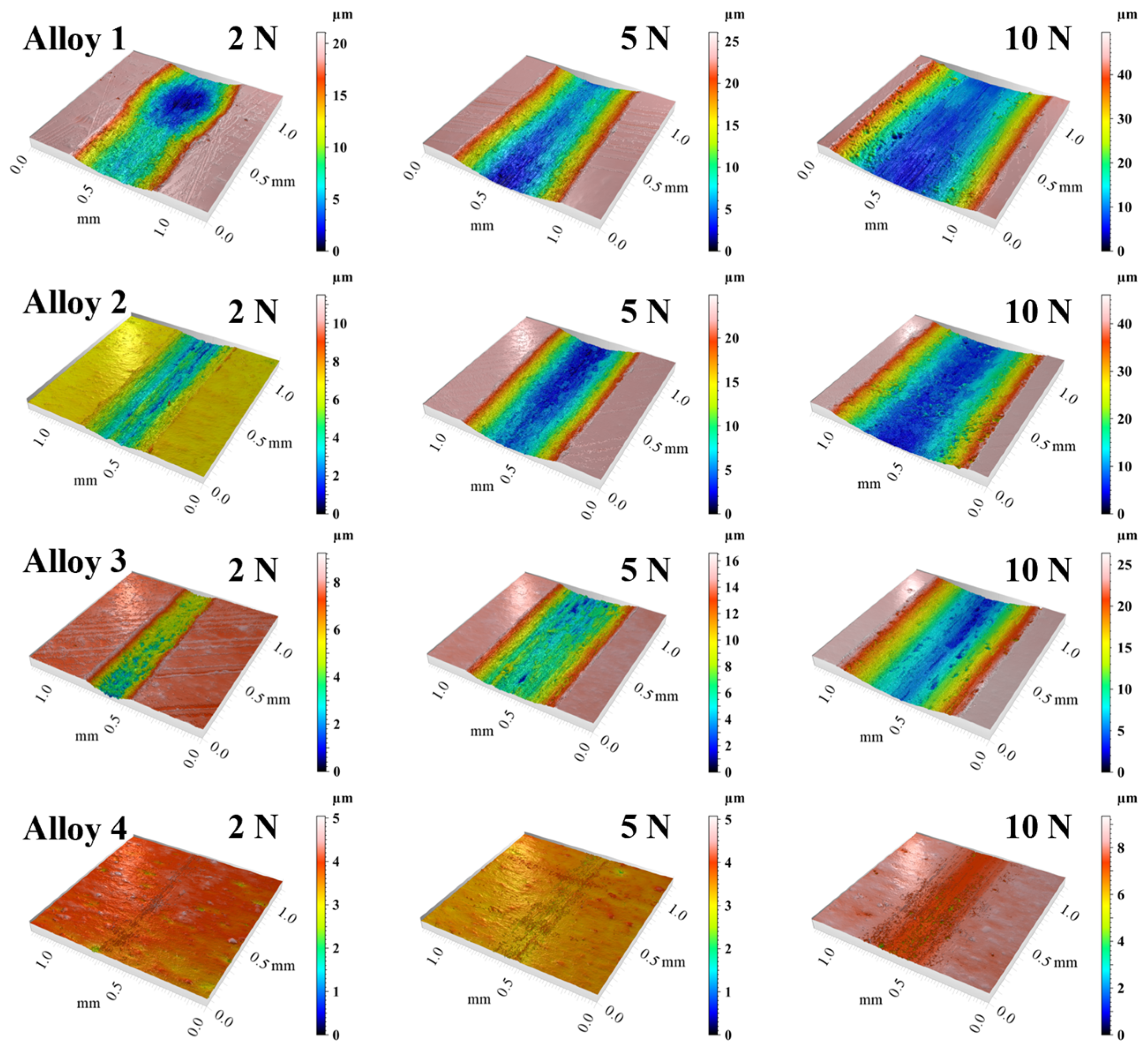
- In tribological testing, the WR decreases significantly with increasing TiC content, indicating an improvement in wear resistance. The wear volumes of alloy 1 under loads of 2 N, 5 N, and 10 N are 2.712 × 10⁻², 4.613 × 10⁻², and 1.088 × 10⁻¹ mm3, respectively. For alloy 2, the wear volumes under the same loads are 1.296 × 10⁻², 4.080 × 10⁻², and 9.164 × 10⁻² mm3. The wear volumes for alloy 3 are 8.83 × 10⁻⁴, 1.686 × 10⁻², and 4.298 × 10⁻² mm3. The wear volumes for alloy 4 are 1.771 × 10⁻⁴, 3.93 × 10⁻⁴, and 1.208 × 10⁻³ mm3, respectively.
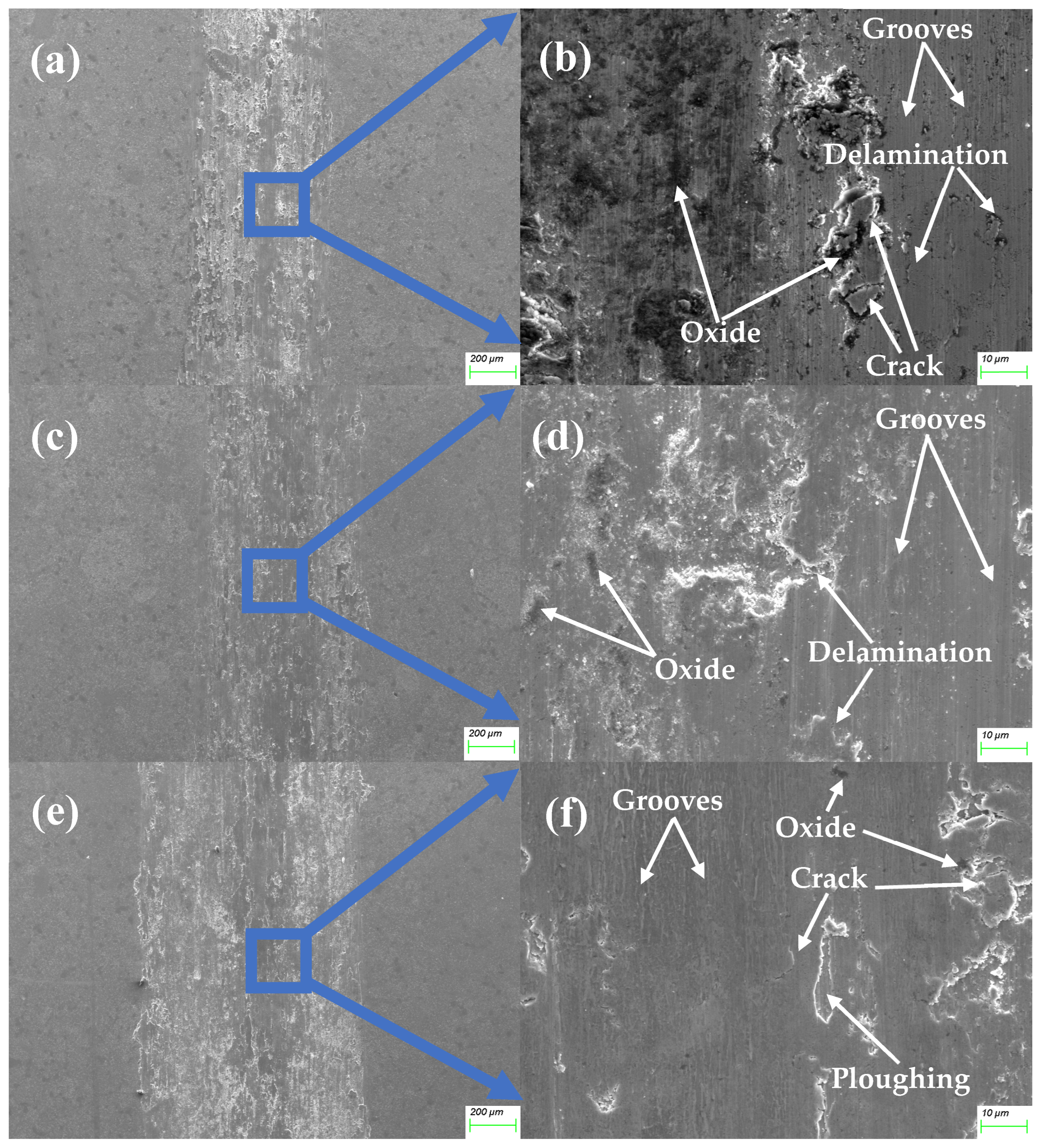
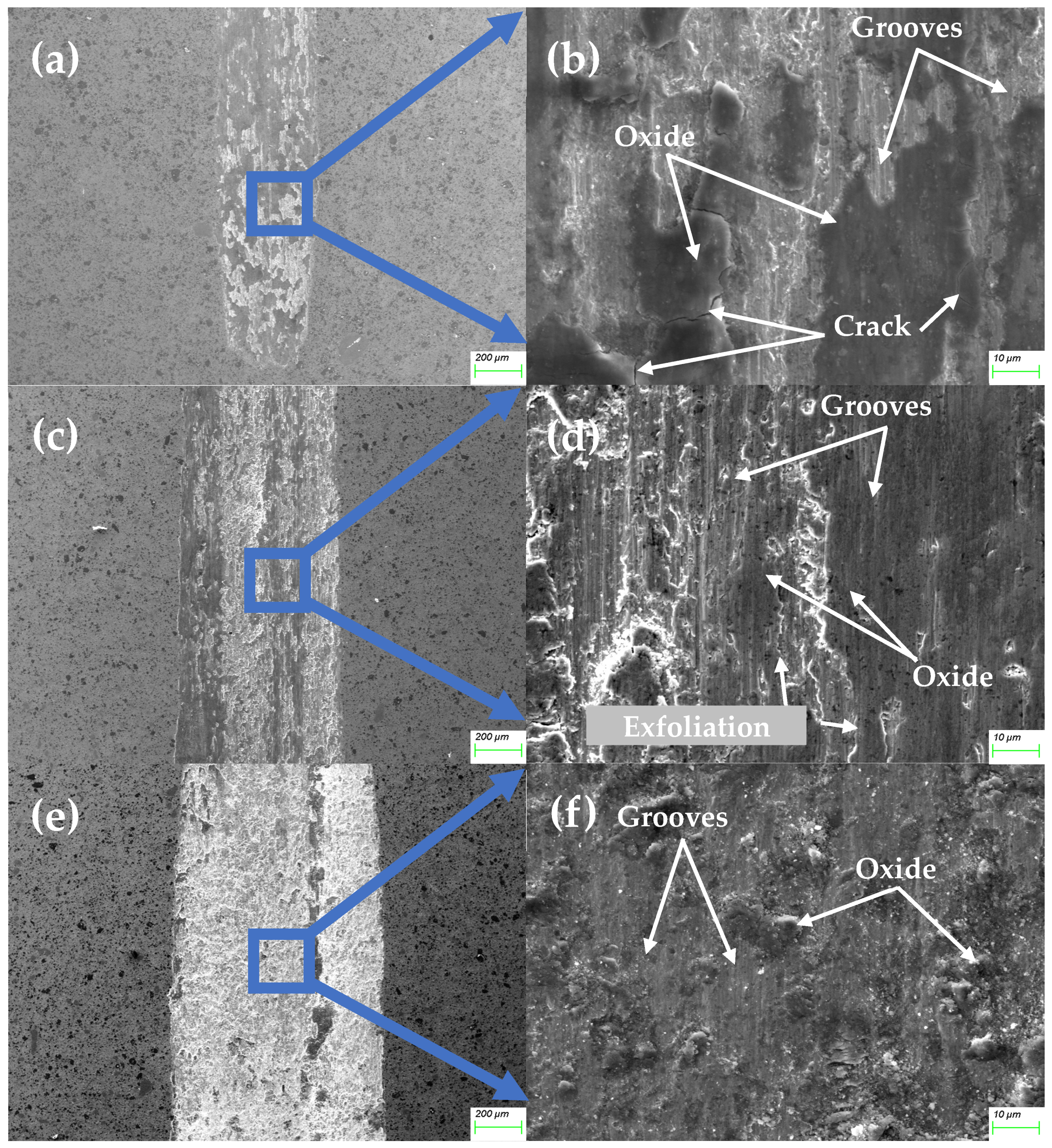
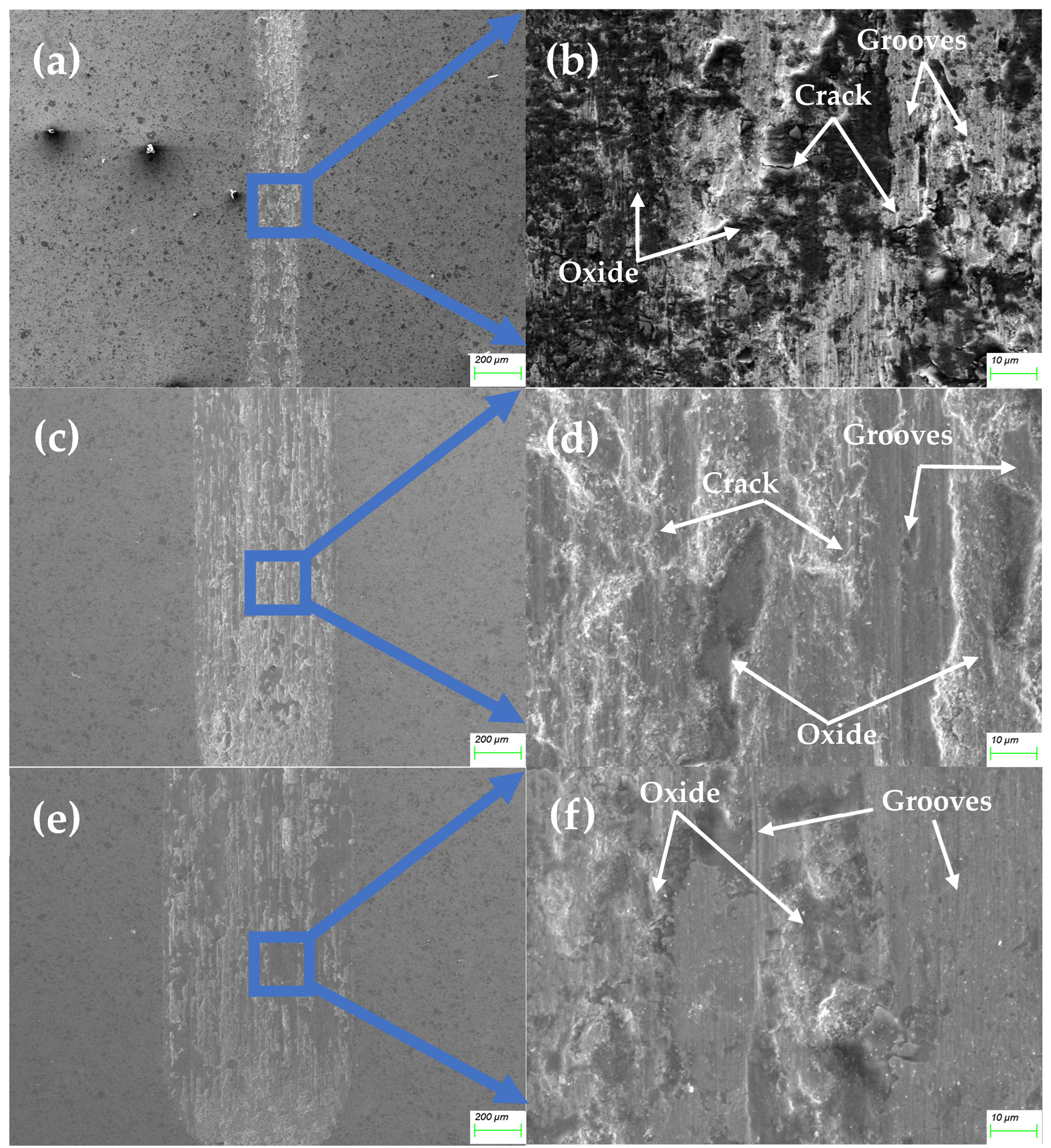
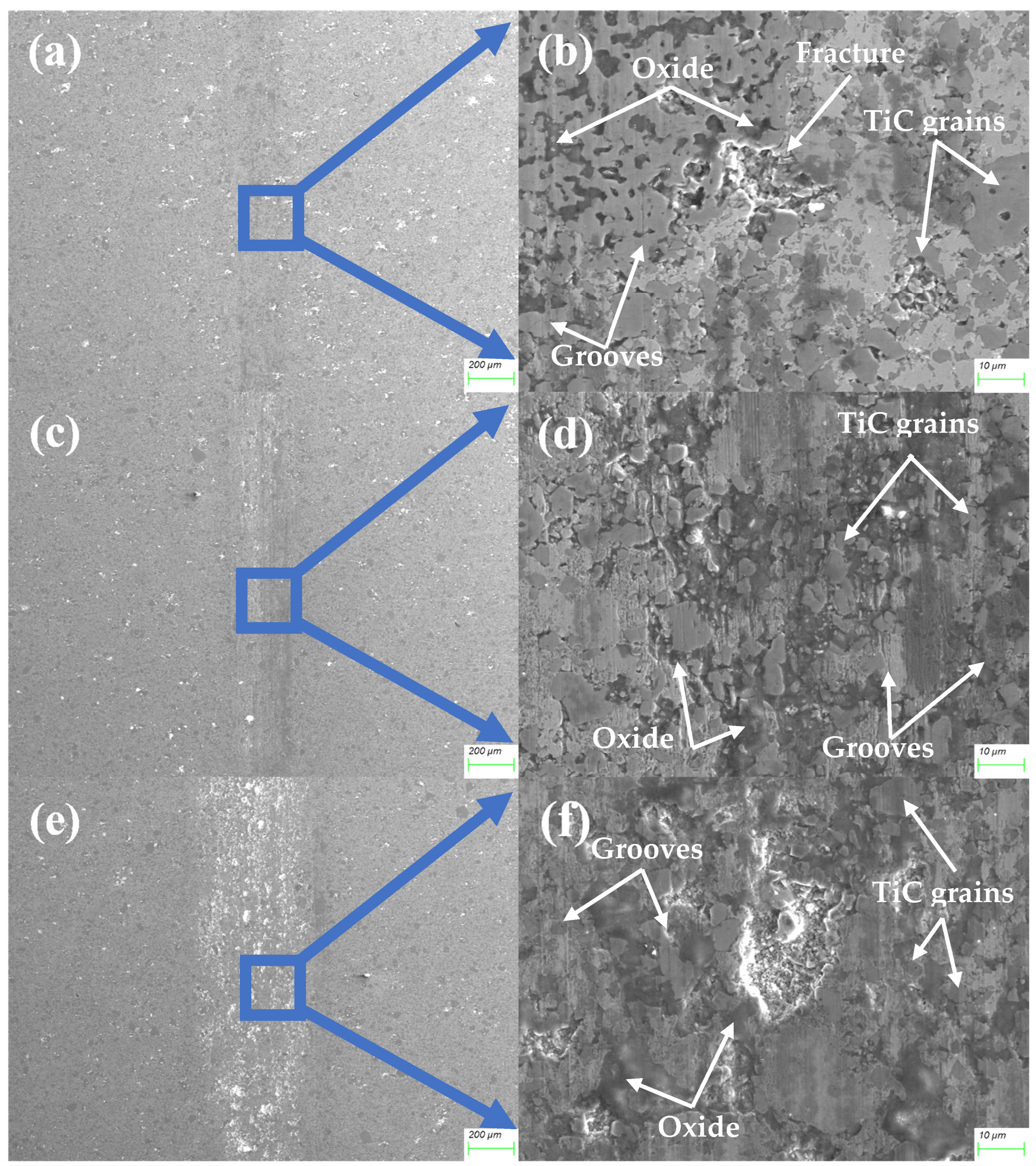
- The primary wear mechanisms for the basic alloy are adhesive wear and oxidative wear. Due to the lower hardness, significant plastic deformation and microcracks occur during friction. As the TiC content increases, the wear mechanism gradually changes to abrasive wear. A strong protective layer forms, particularly for high-TiC-content alloys, effectively reducing wear. The alloy with the highest TiC content (40% TiC) exhibits mild abrasive wear, significantly reducing wear volume and wear rate.
Author Contributions
Funding
Data Availability Statement
Conflicts of Interest
References
- Yeh, J.W.; Chen, S.K.; Lin, S.J.; Gan, J.Y.; Chin, T.S.; Shun, T.T.; Tsau, C.H.; Chang, S.Y. Nanostructured high-entropy alloys with multiple principal elements: Novel alloy design concepts and outcomes. Adv. Eng. Mater. 2004, 6, 299–303. [Google Scholar] [CrossRef]
- Cantor, B.; Chang, I.T.H.; Knight, P.; Vincent, A.J.B. Microstructural development in equiatomic multicomponent alloys. Mat. Sci. Eng. A—Struct. 2004, 375, 213–218. [Google Scholar] [CrossRef]
- Senkov, O.N.; Miller, J.D.; Miracle, D.B.; Woodward, C. Accelerated exploration of multi-principal element alloys for structural applications. Calphad 2015, 50, 32–48. [Google Scholar] [CrossRef]
- Miracle, D.B.; Senkov, O.N. A critical review of high entropy alloys and related concepts. Acta Mater. 2017, 122, 448–511. [Google Scholar] [CrossRef]
- Meghwal, A.; Anupam, A.; Schulz, C.; Hall, C.; Murty, B.S.; Kottada, R.S.; Vijay, R.; Munroe, P.; Berndt, C.C.; Ang, A.S.M. Tribological and corrosion performance of an atmospheric plasma sprayed AlCoCr0.5Ni high-entropy alloy coating. Wear 2022, 506, 204443. [Google Scholar] [CrossRef]
- Xin, S.W.; Shen, X.; Du, C.C.; Zhao, J.; Sun, B.R.; Xue, H.X.; Yang, T.T.; Cai, X.C.; Shen, T.D. Bulk nanocrystalline boron-doped VNbMoTaW high entropy alloys with ultrahigh strength, hardness, and resistivity. J. Alloys Compd. 2021, 853, 155995. [Google Scholar] [CrossRef]
- Nong, Z.-S.; Lei, Y.-N.; Zhu, J.-C. Wear and oxidation resistances of AlCrFeNiTi-based high entropy alloys. Intermetallics 2018, 101, 144–151. [Google Scholar] [CrossRef]
- Onate Soto, A.; Salas Salgado, A.; Berrio Nino, E. Thermodynamic analysis of high entropy alloys and their mechanical behavior in high and low-temperature conditions with a microstructural approach—A review. Intermetallics 2020, 124, 106850. [Google Scholar] [CrossRef]
- Xin, B.; Zhang, A.; Han, J.; Meng, J. The tribological properties of carbon doped Al0.2Co1.5CrFeNi1.5Ti0.5 high entropy alloys. Wear 2021, 484, 204045. [Google Scholar] [CrossRef]
- Zhang, M.; Jiang, Z.; Niu, M.; Sun, Y.; Zhang, X. Tribological behavior of CoCrFeNiMn high-entropy alloy against 304, Al2O3 and Si3N4 counterparts. Wear 2022, 508, 204471. [Google Scholar] [CrossRef]
- Wang, X.; Zhang, Y. Microstructures and corrosion resistance properties of as-cast and homogenized AlFeNiCuCr high entropy alloy. Mater. Chem. Phys. 2020, 254, 123440. [Google Scholar] [CrossRef]
- Kong, D.; Wang, W.; Zhang, T.; Guo, J. Effect of superheating on microstructure and wear resistance of Al1.8CrCuFeNi2 high-entropy alloy. Mater. Lett. 2022, 311, 131613. [Google Scholar] [CrossRef]
- Hsu, C.Y.; Yeh, J.W.; Chen, S.K.; Shun, T.T. Wear resistance and high-temperature compression strength of Fcc CuCoNiCrAl0.5Fe alloy with boron addition. Metall. Mater. Trans. A 2004, 35A, 1465–1469. [Google Scholar] [CrossRef]
- Khorshid, M.T.; Jahromi, S.A.J.; Moshksar, M.M. Mechanical properties of tri-modal Al matrix composites reinforced by nano- and submicron-sized Al2O3 particulates developed by wet attrition milling and hot extrusion. Mater. Des. 2010, 31, 3880–3884. [Google Scholar] [CrossRef]
- Casati, R.; Vedani, M. Metal Matrix Composites Reinforced by Nano-Particles—A Review. Metals 2014, 4, 65–83. [Google Scholar] [CrossRef]
- Chen, C.-S.; Yang, C.-C.; Chai, H.-Y.; Yeh, J.-W.; Chau, J.L.H. Novel cermet material of WC/multi-element alloy. Int. J. Refract. Met. Hard Mater. 2014, 43, 200–204. [Google Scholar] [CrossRef]
- Zhu, G.; Liu, Y.; Ye, J. Early high-temperature oxidation behavior of Ti(C,N)-based cermets with multi-component AlCoCrFeNi high-entropy alloy binder. Int. J. Refract. Met. Hard Mater. 2014, 44, 35–41. [Google Scholar] [CrossRef]
- Rogal, L.; Kalita, D.; Litynska-Dobrzynska, L. CoCrFeMnNi high entropy alloy matrix nanocomposite with addition of Al2O3. Intermetallics 2017, 86, 104–109. [Google Scholar] [CrossRef]
- Shen, Q.; Kong, X.; Chen, X.; Yao, X.; Deev, V.B.; Prusov, E.S. Powder plasma arc additive manufactured CoCrFeNi(SiC)x high-entropy alloys: Microstructure and mechanical properties. Mater. Lett. 2021, 282, 128736. [Google Scholar] [CrossRef]
- Cai, Y.; Zhu, L.; Cui, Y.; Shan, M.; Li, H.; Xin, Y.; Han, J. Fracture and wear mechanisms of FeMnCrNiCo plus x(TiC) composite high-entropy alloy cladding layers. Appl. Surf. Sci. 2021, 543, 148794. [Google Scholar] [CrossRef]
- Zhang, J.; Yu, Y.; Tang, J.; Wang, Y.; Sun, H.; Song, K.; Gong, J.; Liu, P.; Liu, X.; Hu, L.; et al. Unveiling microstructural evolution and enhanced wear resistance of Co37Cr28Ni31Al2Ti2 multicomponent alloy via high-carbon addition. Wear 2024, 536, 205144. [Google Scholar] [CrossRef]
- Shen, L.; Zhao, Y.; Li, Y.; Wu, H.; Zhu, H.; Xie, Z. Synergistic strengthening of FeCrNiCo high entropy alloys via micro-TiC and nano-SiC particles. Mater. Today Commun. 2021, 26, 101729. [Google Scholar] [CrossRef]
- Shepelev, D.; Klempf, J.; Bamberger, M.; Katsman, A. Grain refinement and mechanical properties enhancement of AZ91E alloy by addition of ceramic particles. J. Mater. Sci. 2011, 46, 5798–5806. [Google Scholar] [CrossRef]
- Cheng, J.; Liu, D.; Liang, X.; Chen, Y. Evolution of microstructure and mechanical properties of in situ synthesized TiC-TiB2/CoCrCuFeNi high entropy alloy coatings. Surf. Coat. Technol. 2015, 281, 109–116. [Google Scholar] [CrossRef]
- Sun, X.; Zhu, H.; Li, J.; Huang, J.; Xie, Z. High entropy alloy FeCoNiCu matrix composites reinforced with in-situ TiC particles and graphite whiskers. Mater. Chem. Phys. 2018, 220, 449–459. [Google Scholar] [CrossRef]
- Wang, H.W.; Qi, J.Q.; Zou, C.M.; Zhu, D.D.; Wei, Z.J. High-temperature tensile strengths of in situ synthesized TiC/Ti-alloy composites. Mat. Sci. Eng. A—Struct. 2012, 545, 209–213. [Google Scholar] [CrossRef]
- Fan, Q.C.; Li, B.S.; Zhang, Y. The microstructure and properties of (FeCrNiCo)AlxCuy high-entropy alloys and their TiC-reinforced composites. Mat. Sci. Eng. A—Struct. 2014, 598, 244–250. [Google Scholar] [CrossRef]
- Fu, Z.; Koc, R. TiNiFeCrCoAl high-entropy alloys as novel metallic binders for TiB2-TiC based composites. Mat. Sci. Eng. A—Struct. 2018, 735, 302–309. [Google Scholar] [CrossRef]
- He, L.; Tan, Y.-F.; Tan, H.; Zhou, C.-H.; Gao, L. Tribological properties of nanostructured Al2O3-40%TiO2 multiphase ceramic particles reinforced Ni-based alloy composite coatings. Trans. Nonferr. Met. Soc. China 2013, 23, 2618–2627. [Google Scholar] [CrossRef]
- Chen, J.; Huang, L.; Luo, L.; Zan, X.; Wu, Y. Influence of TiC Content on Microstructure and Properties of W-30Cu/TIC Composites. Rare Metal Mat. Eng. 2018, 47, 447–451. [Google Scholar]
- Wang, J.-y.; Fang, J.-h.; Yang, H.-l.; Liu, Z.-l.; Li, R.-d.; Ji, S.-x.; Wang, Y.; Ruan, J.-m. Mechanical properties and wear resistance of medium entropy Fe40Mn40Cr10Co10/TiC composites. Trans. Nonferr. Met. Soc. China 2019, 29, 1484–1494. [Google Scholar] [CrossRef]
- Tong, Y.-g.; Cai, Y.-l.; Hu, Y.-l.; Huang, H.-f.; Zhang, X.-c.; Zhang, H. TiC strengthened CoCrNi medium entropy alloy: Dissolution and precipitation of TiC and its effect on microstructure and performance. Trans. Nonferr. Met. Soc. China 2022, 32, 2266–2275. [Google Scholar] [CrossRef]
- Zhang, X.; Cui, X.; Qi, M.; Zhang, Q.; Qi, Y.; Jin, G. Corrosion and passivation behavior of in-situ TiC reinforced Al0.1CrNbSi0.1TaTiV refractory high entropy alloy coatings via doping C. Corros. Sci. 2024, 227, 111736. [Google Scholar] [CrossRef]
- Zhang, Z.; Zhang, B.; Zhu, S.; Yu, Y.; Wang, Z.; Zhang, X.; Bin, L. Microstructural characteristics and enhanced wear resistance of nanoscale Al2O3/13 wt%TiO2-reinforced CoCrFeMnNi high entropy coatings. Surf. Coat. Technol. 2021, 412, 127019. [Google Scholar] [CrossRef]
- Yadav, S.; Aggrawal, A.; Kumar, A.; Biswas, K. Effect of TiB2 addition on wear behavior of (AlCrFeMnV)90Bi10 high entropy alloy composite. Tribol. Int. 2019, 132, 62–74. [Google Scholar] [CrossRef]
- Jiang, P.F.; Zhang, C.H.; Zhang, S.; Zhang, J.B.; Chen, J.; Liu, Y. Fabrication and wear behavior of TiC reinforced FeCoCrAlCu-based high entropy alloy coatings by laser surface alloying. Mater. Chem. Phys. 2020, 255, 123571. [Google Scholar] [CrossRef]
- Ye, F.; Yang, Y.; Lou, Z.; Feng, L.; Guo, L.; Yu, J. Microstructure and wear resistance of TiC reinforced AlCoCrFeNi2.1 eutectic high entropy alloy layer fabricated by micro-plasma cladding. Mater. Lett. 2021, 284, 128859. [Google Scholar] [CrossRef]
- Jiang, W.; Yuan, S.; Cao, Y.; Zhang, Y.; Zhao, Y. Mechanical properties and deformation mechanisms of a Ni2Co1Fe1V0.5Mo0.2 medium-entropy alloy at elevated temperatures. Acta Mater. 2021, 213, 116982. [Google Scholar] [CrossRef]
- Shichalin, O.O.; Belov, A.A.; Zavyalov, A.P.; Papynov, E.K.; Azon, S.A.; Fedorets, A.N.; Buravlev, I.Y.; Balanov, M.I.; Tananaev, I.G.; Shi, Y.; et al. Reaction synthesis of SrTiO3 mineral-like ceramics for strontium-90 immobilization via additional in-situ synchrotron studies. Ceram. Int. 2022, 48, 19597–19605. [Google Scholar] [CrossRef]
- Xiao, J.-K.; Tan, H.; Chen, J.; Martini, A.; Zhang, C. Effect of carbon content on microstructure, hardness and wear resistance of CoCrFeMnNiCx high-entropy alloys. J. Alloys Compd. 2020, 847, 156533. [Google Scholar] [CrossRef]
- Colaço, R. From nano and microcontacts to wear of materials. In Fundamentals of Friction and Wear on the Nanoscale; Springer: Berlin/Heidelberg, Germany, 2014; pp. 517–543. [Google Scholar]
- Gahr, K.H.Z. Microstructure and Wear of Materials; Elsevier: Amsterdam, The Netherlands, 1987. [Google Scholar]
- Çetinkaya, C. An investigation of the wear behaviours of white cast irons under different compositions. Mater. Des. 2006, 27, 437–445. [Google Scholar] [CrossRef]
- Berns, H. Comparison of wear resistant MMC and white cast iron. Wear 2003, 254, 47–54. [Google Scholar] [CrossRef]
- Zum Gahr, K.H. Wear by hard particles. Tribol. Int. 1998, 31, 587–596. [Google Scholar] [CrossRef]
- Zum Gahr, K.H.; Eldis, G.T. Abrasive wear of white cast irons. Wear 1980, 64, 175–194. [Google Scholar] [CrossRef]
- Hou, J.; Zhang, M.; Yang, H.; Qiao, J.; Wu, Y. Surface strengthening in Al0.25CoCrFeNi high-entropy alloy by boronizing. Mater. Lett. 2019, 238, 258–260. [Google Scholar] [CrossRef]
- Geng, Y.; Chen, J.; Tan, H.; Cheng, J.; Zhu, S.; Yang, J. Tribological performances of CoCrFeNiAl high entropy alloy matrix solid-lubricating composites over a wide temperature range. Tribol. Int. 2021, 157, 106912. [Google Scholar] [CrossRef]
- Wei, M.X.; Chen, K.M.; Wang, S.Q.; Cui, X.H. Analysis for Wear Behaviors of Oxidative Wear. Tribol. Lett. 2011, 42, 1–7. [Google Scholar] [CrossRef]
- Deng, G.; Tieu, A.K.; Su, L.; Wang, P.; Wang, L.; Lan, X.; Cui, S.; Zhu, H. Investigation into reciprocating dry sliding friction and wear properties of bulk CoCrFeNiMo high entropy alloys fabricated by spark plasma sintering and subsequent cold rolling processes: Role of Mo element concentration. Wear 2020, 460, 203440. [Google Scholar] [CrossRef]
- Liu, Y.; Zhang, F.; Huang, Z.; Zhou, Q.; Ren, Y.; Du, Y.; Wang, H. Mechanical and dry sliding tribological properties of CoCrNiNbx medium-entropy alloys at room temperature. Tribol. Int. 2021, 163, 107160. [Google Scholar] [CrossRef]
- Bhardwaj, V.; Zhou, Q.; Zhang, F.; Han, W.; Du, Y.; Hua, K.; Wang, H. Effect of Al addition on the microstructure, mechanical and wear properties of TiZrNbHf refractory high entropy alloys. Tribol. Int. 2021, 160, 107031. [Google Scholar] [CrossRef]
- Du, Y.; Pei, X.; Tang, Z.; Zhang, F.; Zhou, Q.; Wang, H.; Liu, W. Mechanical and tribological performance of CoCrNiHfx eutectic medium-entropy alloys. J. Mater. Sci. Technol. 2021, 90, 194–204. [Google Scholar] [CrossRef]
- Wu, Y.H.; Yang, H.J.; Guo, R.P.; Wang, X.J.; Shi, X.H.; Liaw, P.K.; Qiao, J.W. Tribological behavior of boronized Al0.1CoCrFeNi high-entropy alloys under dry and lubricated conditions. Wear 2020, 460, 203452. [Google Scholar] [CrossRef]
- Cherepova, T.S.; Dmytrieva, H.P.; Dukhota, O.I.; Kindrachuk, M.V. Properties of nickel powder alloys hardened with titanium carbide. J. Mater. 2016, 52, 173–179. [Google Scholar] [CrossRef]
- Kindrachuk, V.; Wanderka, N.; Banhart, J.; Mukherji, D.; Del Genovese, D.; Rösler, J. Effect of rhenium addition on the microstructure of the superalloy Inconel 706. Acta Mater. 2008, 56, 1609–1618. [Google Scholar] [CrossRef]
- Kindrachuk, V.; Fedelich, B.; Rehmer, B.; Peter, F. Computational Methods for Lifetime Prediction of Metallic Components under High-Temperature Fatigue. Metals 2019, 9, 390. [Google Scholar] [CrossRef]
- Pashechko, M.; Vasyliv, C. Solubility of metals in low-melting melts. Int. J. Mater. Res. 1997, 88, 484–488. [Google Scholar]
- Kindrachuk, V.M.; Kamachali, R.D. Mean-field modeling and Phase-field simulation of Grain Growth under Directional driving forces. Materialia 2024, 33, 101989. [Google Scholar] [CrossRef]
- Holubets, V.M.; Pashechko, M.I.; Dzedzic, K.; Borc, J.; Tisov, A.V. Frictional Strength of Electric Spark Coatings from Powder Wires under Friction without Lubrication. J. Frict. Wear 2020, 41, 443–446. [Google Scholar] [CrossRef]
- Kindrachuk, M.V.; Dushek, Y.Y.; Luchka, M.V.; Gladchenko, A.N. Evolution of the structure and properties of eutectic coatings during friction. Powder Metall. Met. Ceram. 1995, 34, 321–326. [Google Scholar] [CrossRef]


| Alloy No. | Elemental Composition, wt.% | |||||
|---|---|---|---|---|---|---|
| Co | Cr | Ni | Al | Ti | TiC | |
| 1 | 38.87 | 25.98 | 32.48 | 0.96 | 1.71 | 0.00 |
| 2 | 34.99 | 23.38 | 29.23 | 0.86 | 1.54 | 10.00 |
| 3 | 31.10 | 20.79 | 25.98 | 0.76 | 1.37 | 20.00 |
| 4 | 23.32 | 15.59 | 19.49 | 0.57 | 1.03 | 40.00 |
| Sample | Elemental Composition, wt.% | |||||
|---|---|---|---|---|---|---|
| Co | Cr | Ni | Al | Ti | C | |
| Alloy 1 | 43.50 | 22.65 | 27.28 | 1.08 | 1.90 | 3.59 |
| Alloy 2 | 33.21 | 16.97 | 28.60 | 1.01 | 11.80 | 8.41 |
| Alloy 3 | 28.04 | 15.85 | 22.40 | 0.80 | 20.99 | 11.56 |
| Alloy 4 | 17.54 | 11.21 | 14.20 | 0.55 | 39.05 | 17.44 |
| Value | Sample | |||
|---|---|---|---|---|
| Alloy 1 | Alloy 2 | Alloy 3 | Alloy 4 | |
| Dry weight, g. | 20.724 | 22.092 | 25.276 | 20.52 |
| Floating weight, g. | 2.740 | 3.121 | 3.736 | 3.675 |
| Wet weight, g. | 20.730 | 22.218 | 25.429 | 21.194 |
| Porosity, % | 0.33 | 0.56 | 0.71 | 3.84 |
| Sample | Theoretical TiC Fraction, vol. % | Calculated Area Fraction of TiC, % | Maximum Size of TiC, μm. | Average Size of TiC, μm. |
|---|---|---|---|---|
| Alloy 2 | 13.83 | 14.79 | 11.53 | 2.52 |
| Alloy 3 | 27.69 | 25.43 | 18.88 | 2.71 |
| Alloy 4 | 48.28 | 44.59 | 28.26 | 3.01 |
| Normal Force, N | Alloy 1 | Alloy 2 | Alloy 3 | Alloy 4 |
|---|---|---|---|---|
| 2 | 0.5035 | 0.5654 | 0.5424 | 0.2251 |
| 5 | 0.5090 | 0.5804 | 0.5596 | 0.2137 |
| 10 | 0.4957 | 0.6203 | 0.6109 | 0.5730 |
| Normal Force, N | Depth, μm | |||
|---|---|---|---|---|
| Alloy 1 | Alloy 2 | Alloy 3 | Alloy 4 | |
| 2 | 17.498 | 4.683 | 4.046 | 0.378 |
| 5 | 21.925 | 20.679 | 10.729 | 0.395 |
| 10 | 39.544 | 39.053 | 19.811 | 1.299 |
| Normal Force, N | Width, mm | |||
|---|---|---|---|---|
| Alloy 1 | Alloy 2 | Alloy 3 | Alloy 4 | |
| 2 | 0.687 | 0.419 | 0.315 | 0.110 |
| 5 | 0.740 | 0.679 | 0.668 | 0.146 |
| 10 | 1.010 | 0.991 | 0.854 | 0.474 |
Disclaimer/Publisher’s Note: The statements, opinions and data contained in all publications are solely those of the individual author(s) and contributor(s) and not of MDPI and/or the editor(s). MDPI and/or the editor(s) disclaim responsibility for any injury to people or property resulting from any ideas, methods, instructions or products referred to in the content. |
© 2025 by the authors. Licensee MDPI, Basel, Switzerland. This article is an open access article distributed under the terms and conditions of the Creative Commons Attribution (CC BY) license (https://creativecommons.org/licenses/by/4.0/).
Share and Cite
Zhao, Y.; Ma, W.; Tisov, O. Enhancing Reciprocating Wear Resistance of Co37Cr28Ni31Al2Ti2 Spark Plasma Sintered Medium-Entropy Alloy via TiC Addition. Materials 2025, 18, 442. https://doi.org/10.3390/ma18020442
Zhao Y, Ma W, Tisov O. Enhancing Reciprocating Wear Resistance of Co37Cr28Ni31Al2Ti2 Spark Plasma Sintered Medium-Entropy Alloy via TiC Addition. Materials. 2025; 18(2):442. https://doi.org/10.3390/ma18020442
Chicago/Turabian StyleZhao, Yubo, Wenbo Ma, and Oleksandr Tisov. 2025. "Enhancing Reciprocating Wear Resistance of Co37Cr28Ni31Al2Ti2 Spark Plasma Sintered Medium-Entropy Alloy via TiC Addition" Materials 18, no. 2: 442. https://doi.org/10.3390/ma18020442
APA StyleZhao, Y., Ma, W., & Tisov, O. (2025). Enhancing Reciprocating Wear Resistance of Co37Cr28Ni31Al2Ti2 Spark Plasma Sintered Medium-Entropy Alloy via TiC Addition. Materials, 18(2), 442. https://doi.org/10.3390/ma18020442