
Surface Modification by Plasma Electrolytic Oxidation of Friction Surfacing 4043 Aluminum-Based Alloys Deposited onto Structural S235 Steel Substrate


Highlights
- Friction surfacing enables the deposition of solid-state aluminum-based coatings on S235 steel, offering a clean, defect-free bond without melting the materials.
- Plasma electrolytic oxidation is an effective surface treatment, particularly for corrosion resistance enhancement in chloride-rich environments.
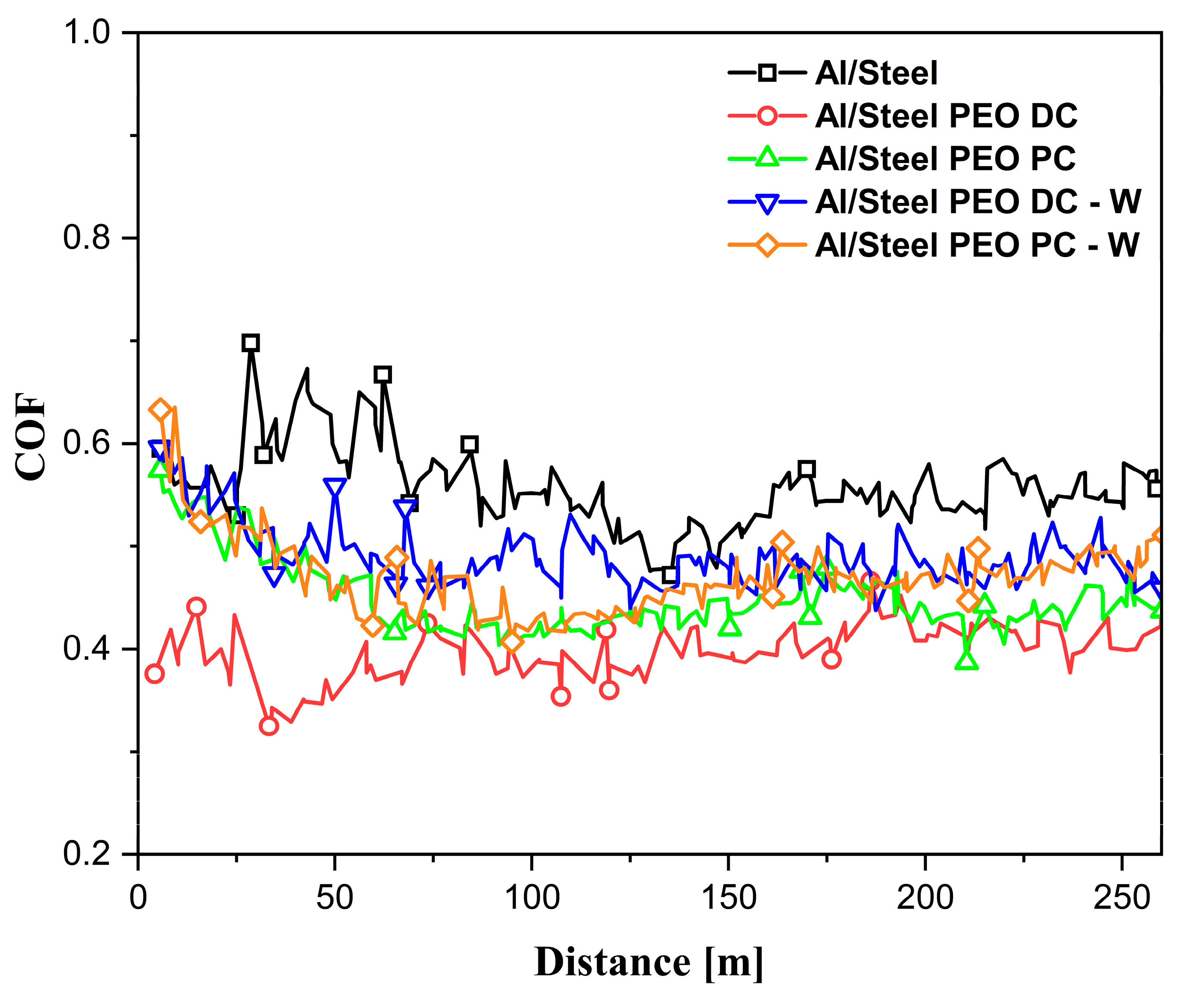
- PEO-treated samples showed improvements in wear resistance by lowering the coefficient of friction.
Abstract
1. Introduction
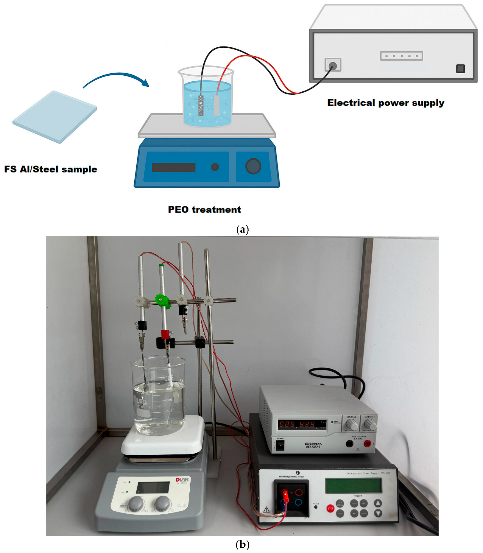
2. Materials and Methods
3. Results and Discussion
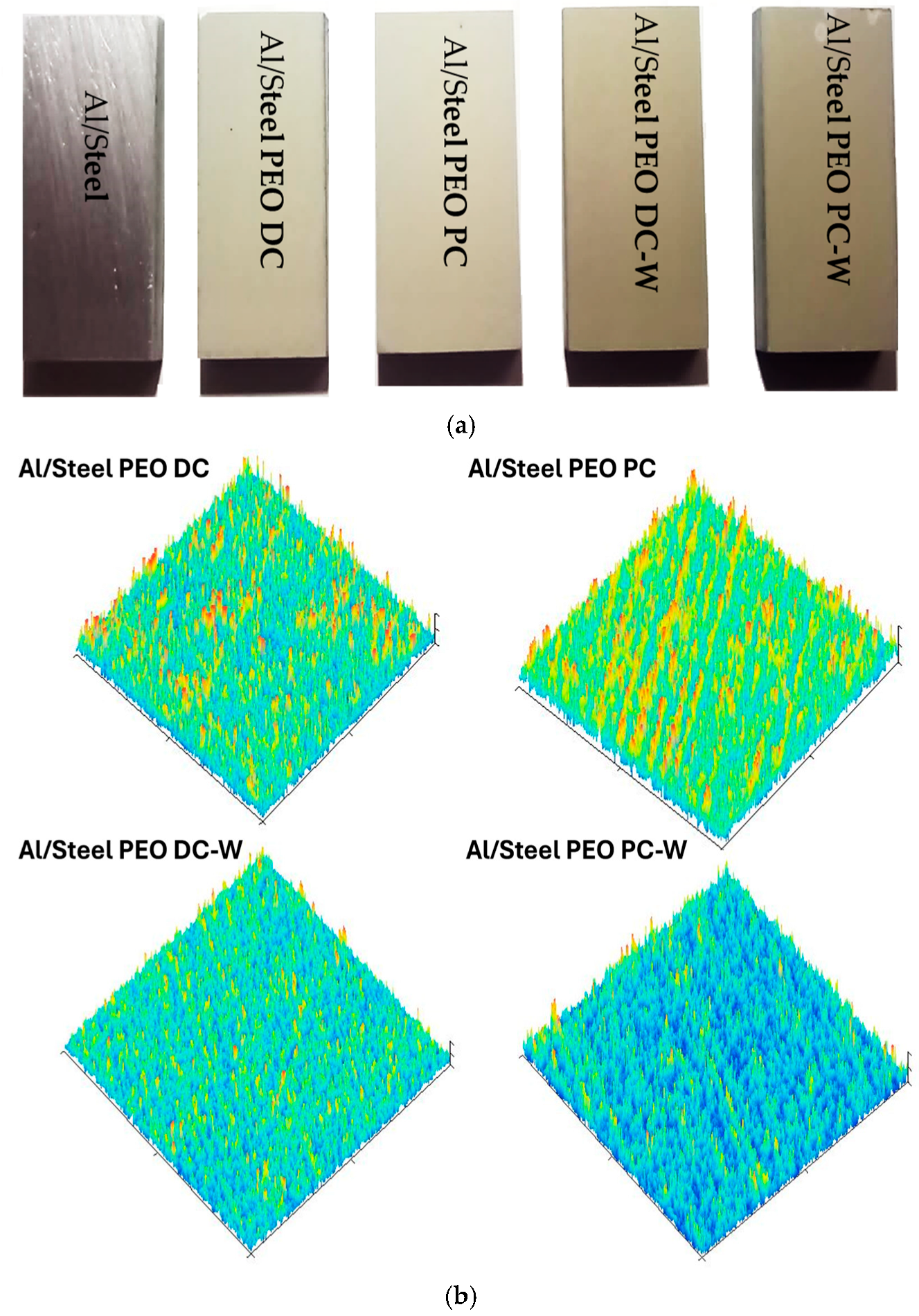
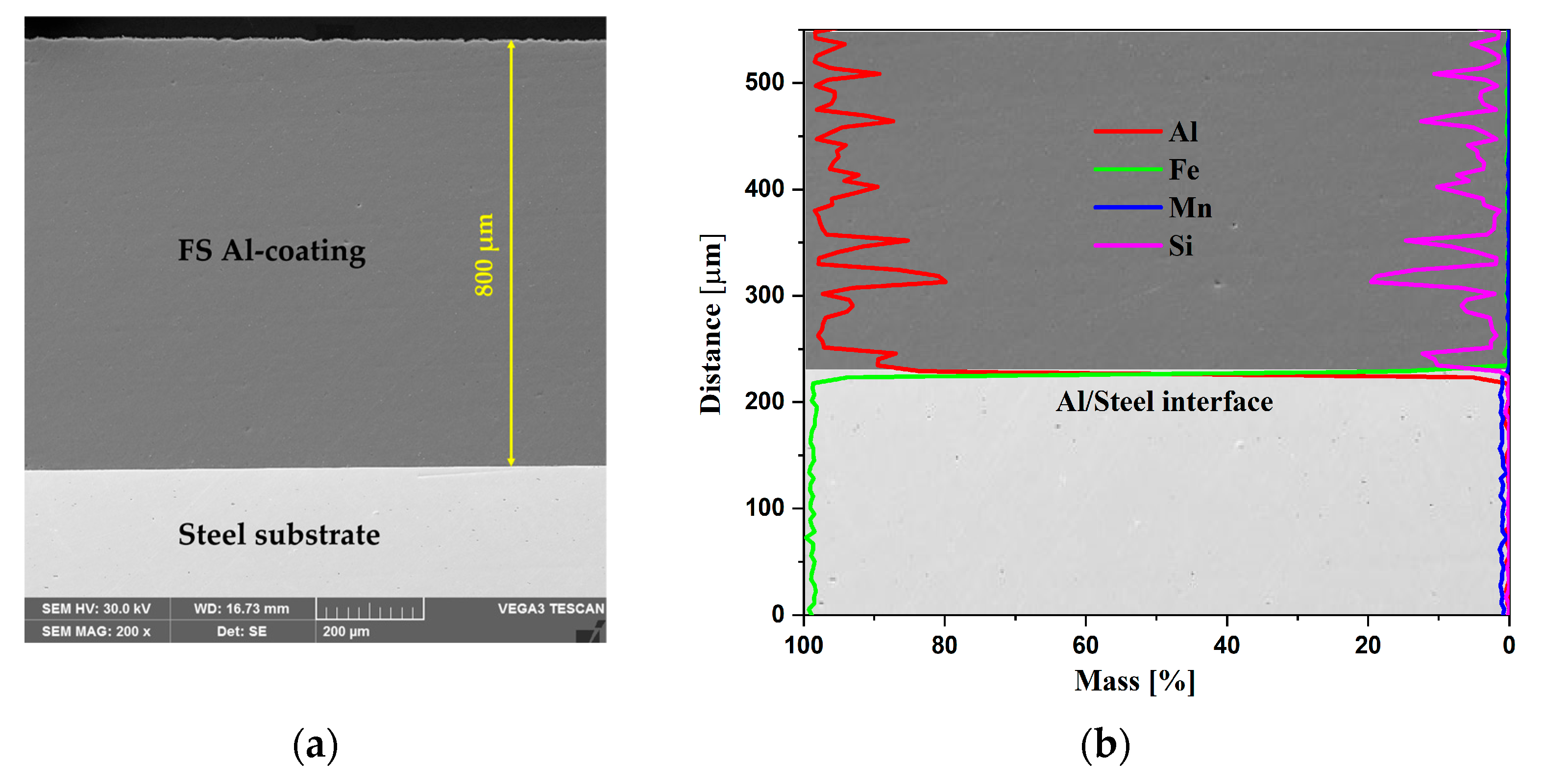
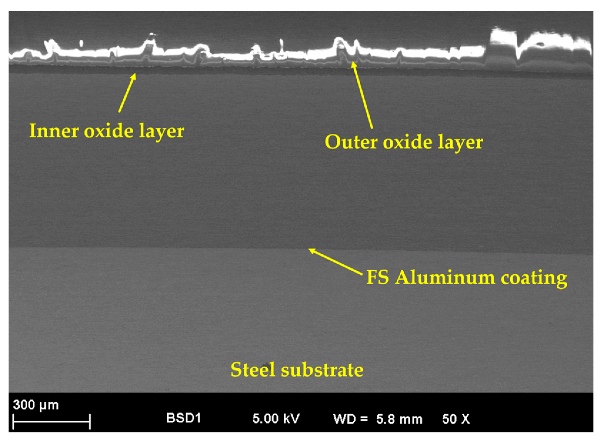
3.1. Morphological, Chemical, and Phase Composition of the FS Al-Based and PEO-Treated Coatings
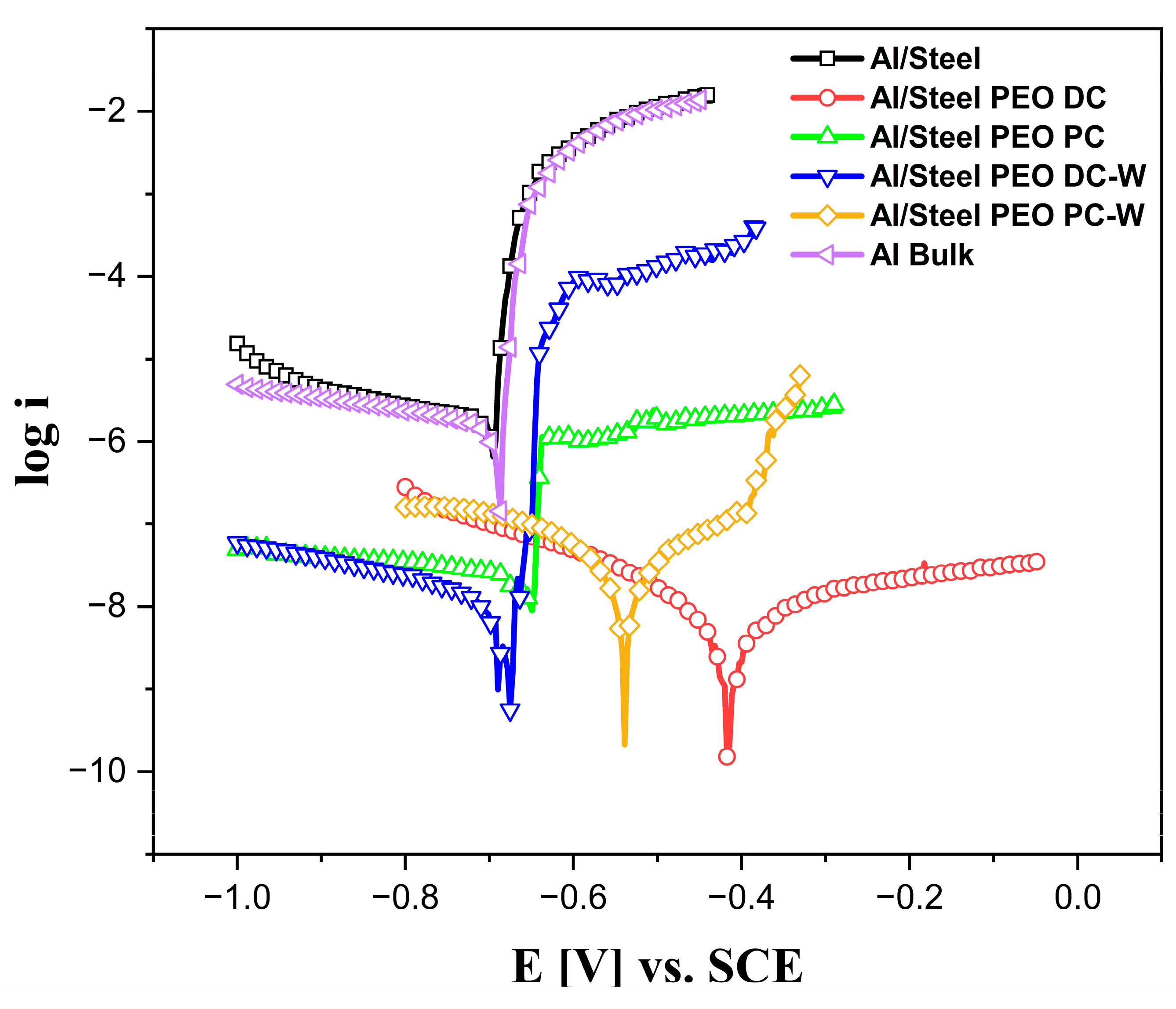
3.2. Corrosion Resistance of the FS Al-Based and PEO-Treated Coatings
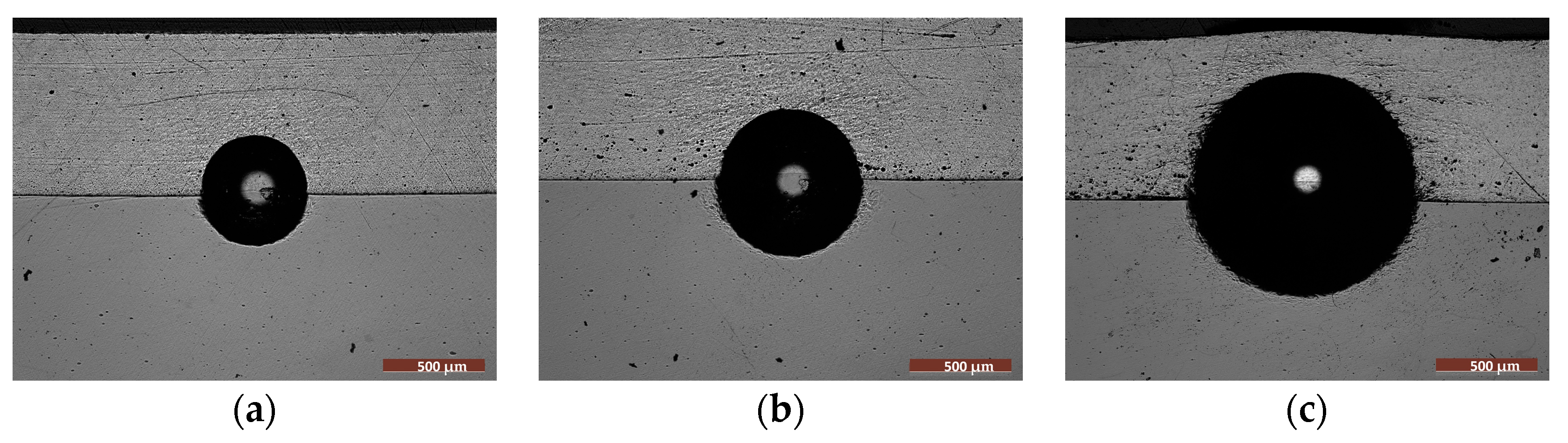
3.3. Wear Behavior of the FS Al-Based and PEO-Treated Coatings
4. Conclusions
- The FS Al-based coatings presented good adhesion to the steel substrate, showing a clean interface with no gaps, cracks, or pores in the SEM cross-section micrographs.
- The PEO process was applied successfully to the aluminum surface from two different electrolytes, and the results showed that the PEO is an effective surface treatment, particularly for corrosion resistance enhancement in chloride-rich environments.
- The improvements were associated with the ability of aluminum to form a thick, adherent, and protective oxide layer during the plasma treatment, which minimized the electrochemical degradation.
- The PEO treatments shifted the corrosion potential of the aluminum surface to more noble values and drastically reduced corrosion current density, indicating lower corrosion rates and improved long-term performance.
- The Al2O3 layer formed during the PEO treatment brought additional benefits in terms of wear resistance.
- The Al/Steel PEO DC sample performed the best, in terms of corrosion and wear resistance, providing the lowest corrosion current densities and the most stable behavior, attributed to the dense and hard Al2O3 layer.
- The improvements in the wear resistance were evidenced by the lower and more stable coefficient of friction across all the PEO-treated samples.
Author Contributions
Funding
Institutional Review Board Statement
Informed Consent Statement
Data Availability Statement
Acknowledgments
Conflicts of Interest
References
- Aminzadegan, S.; Shahriari, M.; Mehranfar, F.; Abramovic, B. Factors affecting the emission of pollutants in different types of transportation: A literature review. Energy Rep. 2022, 8, 2508–2529. [Google Scholar] [CrossRef]
- Aliasghari, S.; Ghorbani, M.; Skedon, P.; Karami, H.; Movahedi, M. Effect of plasma electrolytic oxidation on joining of AA 5052 aluminium alloy to polypropylene using friction stir spot welding. Surf. Coat. Technol. 2017, 313, 274–281. [Google Scholar] [CrossRef]
- Dzhurinskiy, D.; Dautov, S.; Shornikov, P.; Akhatov, I. Surface Modification of Aluminum 6061-O Alloy by Plasma Electrolytic Oxidation to Improve Corrosion Resistance Properties. Coatings 2021, 11, 4. [Google Scholar] [CrossRef]
- Wang, Y.; Paidar, M.; Eslami-Farsani, R.; Ashtiani, H.A.-D.; Salman, S.; Mehrez, S.; Zhang, H. Friction surfacing of AA6061 on AA5083 aluminum alloy with adding 316 stainless steel powders: Effect of volume fraction of reinforcements. J. Mater. Res. Technol. 2024, 30, 1800–1805. [Google Scholar] [CrossRef]
- Bailo, C.; Modi, S.; Schultz, M.; Fiorelli, T.; Smith, B.; Snell, N. Vehicle Mass Reduction Roadmap Study 2025–2035; Center for Automotive Research: Ann Arbor, MI, USA, 2020. [Google Scholar]
- Zhang, W.; Xu, J. Advanced lightweight materials for Automobiles: A review. Mater. Des. 2022, 221, 110994. [Google Scholar] [CrossRef]
- Badheka, K.; Badheka, V. Friction Surfacing Of Aluminium on Steel: An Experimental Approach. Mater. Today Proc. 2017, 4, 9937–9941. [Google Scholar] [CrossRef]
- Klopstock, H.; Neelands, A. GB572789; An Improved Method of Joining or Welding Metals. UK Pat: Leeds, UK, 1941.
- Seidi, E.; Miller, S. A Novel Approach to Friction Surfacing: Experimental Analysis of Deposition from Radial Surface of a Consumable Tool. Coatings 2020, 10, 1016. [Google Scholar] [CrossRef]
- Martins, N.; Silva, A.; Silva, G.D.; Santos, I.D.; Santos, C.D.; Troysi, F.; Brito, P. Characterization of Iron Aluminide Diffusion Coatings Obtained after Friction Surfacing. Metals 2023, 13, 461. [Google Scholar] [CrossRef]
- Vale, N.D.; Fitseva, V.; Hanke, S.; Filho, S.; Santos, J.D. Influence of Rotational Speed in the Friction Surfacing of Titanium Grade 1 on Ti-6Al-4V. Mater. Res. 2017, 20, 830–835. [Google Scholar] [CrossRef]
- Li, H.; Qin, W.; Galloway, A.; Toumpis, A. Friction Surfacing of Aluminium Alloy 5083 on DH36 Steel Plate. Metals 2019, 9, 479. [Google Scholar] [CrossRef]
- Ozcan, M. The influence of parameters on the evolution of the friction surfacing method—a review. J. Mech. Sci. Technol. 2022, 36, 723–730. [Google Scholar] [CrossRef]
- Seidi, E.; Miller, S. Lateral friction surfacing: Experimental and metallurgical analysis of different aluminum alloy depositions. J. Mater. Res. Technol. 2021, 15, 5948–5967. [Google Scholar] [CrossRef]
- Chandrasekaran, M.; Batchelor, A.W.; Jana, S. Friction surfacing of metal coatings on steel and aluminum substrate. J. Mater. Process. Technol. 1997, 72, 446–452. [Google Scholar] [CrossRef]
- Abdelall, E.; Al-Dwairi, A.; Al-Raba’a, S.; Eldakroury, M. Printing functional metallic 3D parts using a hybrid friction surfacing additive manufacturing process. Prog. Addit. Manuf. 2021, 6, 589–590. [Google Scholar] [CrossRef]
- Karar, G.C.; Kumar, R.; Chattopadhyaya, S.; Dewangan, S. Comparative study of AA6061 and AA6063 aluminum alloy coating on mild steel using friction surfacing. Sci. Rep. 2025, 17, 17693. [Google Scholar] [CrossRef]
- Kallien, Z.; Roos, A.; Knothe-Horstmann, C.; Klusemann, B. Temperature-dependent mechanical behavior of aluminum AM structures generated via multi-layer friction surfacing. Mater. Sci. Eng. A 2023, 871, 144872. [Google Scholar] [CrossRef]
- Kallien, Z.; Rath, L.; Roos, A.; Klusemann, B. Experimentally established correlation of friction surfacing process temperature and deposit geometry. Surf. Coat. Technol. 2020, 397, 126040. [Google Scholar] [CrossRef]
- Sugandhi, V. Optimization of Friction Surfacing Process Parameters for AA1100 Aluminum Alloy Coating with Mild Steel Substrate Using Response Surface Methodology (RSM) Technique. Mod. Appl. Sci. 2012, 6, 69–80. [Google Scholar] [CrossRef]
- Rethnam, G.; Manivel, S.; Sharma, V.; Srinivas, C.; Afzal, A.; Razak, A.; Alamri, S.; Saleel, C. Parameter Study on Friction Surfacing of AISI316Ti Stainless Steel over EN8 Carbon Steel and Its Effect on Coating Dimensions and Bond Strength. Materials 2021, 14, 4967. [Google Scholar] [CrossRef]
- Janakiraman, S.; Bhat, K. Formation of Composite Surface during Friction Surfacing of Steel with Aluminium. Adv. Tribol. 2012, 2012, 614278. [Google Scholar] [CrossRef]
- Famiyeh, L.; Huang, X. Plasma Electrolytic Oxidation Coatings on Aluminum Alloys: Microstructures, Properties, and Applications. Mod. Concepts Mater. Sci. 2019, 2, 000526. [Google Scholar] [CrossRef]
- Zhu, L.; Ke, X.; Li, J.; Zhang, Y.; Zhang, Z.; Sui, M. Growth mechanisms for initial stages of plasma electrolytic oxidation coating on Al. Surf. Interfaces 2021, 25, 101186. [Google Scholar] [CrossRef]
- Kasalica, B.; Petkovic-Benazzouz, M.; Sarvan, M.; Belca, I.; Maksimovic, B.; Misailovic, B.; Popovic, Z. Mechanisms of plasma electrolytic oxidation of aluminum at the multi-hour timescales. Surf. Coat. Technol. 2020, 390, 125681. [Google Scholar] [CrossRef]
- Mojsilovic, K.; Tadic, N.; Lacnjevac, U.; Stojadinovic, S.; Vasilic, R. Characterization of Al–W oxide coatings on aluminum formed by pulsed direct current plasma electrolytic oxidation at ultra-low duty cycles. Surf. Coat. Technol. 2021, 411, 126982. [Google Scholar] [CrossRef]
- Muntean, R.; Brîndușoiu, M.; Buzdugan, D.; Nemeș, N.; Kellenberger, A.; Uțu, I. Characteristics of Hydroxyapatite-Modified Coatings Based on TiO2 Obtained by Plasma Electrolytic Oxidation and Electrophoretic Deposition. Materials 2023, 16, 1410. [Google Scholar] [CrossRef]
- Rafi, H.K.; Ram, G.; Phanikumar, G.; Rao, K. Friction surfaced tool steel (H13) coatings on low carbon steel: A study on the effects of process parameters on coating characteristics and integrity. Surf. Coat. Technol. 2010, 205, 232–242. [Google Scholar] [CrossRef]
- ASTM E3-11; Standard Guide for Preparation of Metallographic Specimens. ASTM International: West Conshohocken, PA, USA, 2017.
- ASTM G99-17; Standard Test Method for Wear Testing with a Pin-On-Disk Apparatus. ASTM International: West Conshohocken, PA, USA, 2017.
- Roos, A.; Metternich, F.; Kallien, Z.; Baumann, J.; Ehrich, J.; Kipp, M.; Hanke, S.; Biermann, D.; Klusemann, B. Friction surfacing of aluminum to steel: Influence of different substrate surface topographies. Mater. Des. 2023, 235, 112390. [Google Scholar] [CrossRef]
- Fernández-López, P.; Alves, S.A.; San-Jose, J.T.; Gutierrez-Berasategui, E.; Bayón, R. Plasma Electrolytic Oxidation (PEO) as a Promising Technology for the Development of High-Performance Coatings on Cast Al-Si Alloys: A Review. Coatings 2024, 14, 217. [Google Scholar] [CrossRef]
- Mengesha, G.A.; Chu, J.P.; Lou, B.-S.; Lee, J.-W. Effects of Processing Parameters on the Corrosion Performance of Plasma Electrolytic Oxidation Grown Oxide on Commercially Pure Aluminum. Metals 2020, 10, 394. [Google Scholar] [CrossRef]
- Gandra, J.; Miranda, R.; Vilaca, P. Performance analysis of friction surfacing. J. Mater. Process. Technol. 2012, 212, 1676–1686. [Google Scholar] [CrossRef]
- Lucas, R.R.; Silva, E.R.R.; Marques, L.F.B.; da Silva, F.J.G.; Abrahão, A.B.R.M.; Vieira, M.d.O.L.; Hein, L.R.d.O.; Botelho, E.C.; Mota, R.P.; Sales-Contini, R.d.C.M. Analysis of Plasma Electrolytic Oxidation Process Parameters for Optimizing Adhesion in Aluminum–Composite Hybrid Structures. Appl. Sci. 2024, 14, 7972. [Google Scholar] [CrossRef]


| Material | Chemical Composition (wt.%) | ||||||||
|---|---|---|---|---|---|---|---|---|---|
| S235 steel | C | Mn | P | S | N | Cu | Fe | ||
| 0.16 ± 0.005 | 1.23 ± 0.01 | 0.014 ± 0.001 | 0.008 ± 0.001 | 0.01 ± 0.002 | 0.5 ± 0.05 | Bal. | |||
| 4043 aluminum-based alloy | Si | Fe | Cu | Mn | Mg | Zn | Others | Al | |
| 4.5 ± 1 | 0.35 ± 0.05 | 0.03 ± 0.02 | 0.03 ± 0.02 | 0.03 ± 0.02 | 0.007 ± 0.003 | 0.12 ± 0.03 | Bal. | ||
| Sample | Treatment Conditions | |||
|---|---|---|---|---|
| Current Density [mA cm−2] /Voltage [V] | Total Time [s] | d.c. [%] | Electrolyte | |
| Al/Steel PEO DC | 30 mA cm−2 /max 370 V | 1800 | - | 4 g L−1 KOH + 20 g L−1 Na2SiO3 |
| Al/Steel PEO PC | 7200 | 20 | ||
| Al/Steel PEO DC-W | 1800 | - | 4 g L−1 KOH + 3 g L−1 Na2WO4·2H2O | |
| Al/Steel PEO PC-W | 7200 | 20 | ||
| Scheme 106 | OCP [V] | icorr·106 [A cm−2] | Ecorr [V] | Corr Rate 103 [mm per year] |
|---|---|---|---|---|
| Al/Steel | −0.68 ± 0.05 | 1.66 | −0.69 | 19 |
| Al/Steel PEO DC | −0.43 ± 0.02 | 0.0075 | −0.41 | 0.086 |
| Al/Steel PEO PC | −0.64 ± 0.07 | 0.0265 | −0.66 | 0.31 |
| Al/Steel PEO DC-W | −0.66 ± 0.08 | 0.0115 | −0.68 | 0.13 |
| Al/Steel PEO PC-W | −0.55 ± 0.03 | 0.0204 | −0.53 | 0.23 |
| Al Bulk | −0.68 ± 0.05 | 1.57 | −0.69 | 18 |
| Sample | μmin | μaverage | μmax |
|---|---|---|---|
| Al/Steel | 0.462 | 0.560 | 0.938 |
| Al/Steel PEO DC | 0.324 | 0.394 | 0.466 |
| Al/Steel PEO PC | 0.387 | 0.452 | 0.758 |
| Al/Steel PEO DC-W | 0.437 | 0.493 | 0.673 |
| Al/Steel PEO PC-W | 0.404 | 0.471 | 0.705 |
Disclaimer/Publisher’s Note: The statements, opinions and data contained in all publications are solely those of the individual author(s) and contributor(s) and not of MDPI and/or the editor(s). MDPI and/or the editor(s) disclaim responsibility for any injury to people or property resulting from any ideas, methods, instructions or products referred to in the content. |
© 2025 by the authors. Licensee MDPI, Basel, Switzerland. This article is an open access article distributed under the terms and conditions of the Creative Commons Attribution (CC BY) license (https://creativecommons.org/licenses/by/4.0/).
Share and Cite
Muntean, R.; Uțu, I.-D. Surface Modification by Plasma Electrolytic Oxidation of Friction Surfacing 4043 Aluminum-Based Alloys Deposited onto Structural S235 Steel Substrate. Materials 2025, 18, 3302. https://doi.org/10.3390/ma18143302
Muntean R, Uțu I-D. Surface Modification by Plasma Electrolytic Oxidation of Friction Surfacing 4043 Aluminum-Based Alloys Deposited onto Structural S235 Steel Substrate. Materials. 2025; 18(14):3302. https://doi.org/10.3390/ma18143302
Chicago/Turabian StyleMuntean, Roxana, and Ion-Dragoș Uțu. 2025. "Surface Modification by Plasma Electrolytic Oxidation of Friction Surfacing 4043 Aluminum-Based Alloys Deposited onto Structural S235 Steel Substrate" Materials 18, no. 14: 3302. https://doi.org/10.3390/ma18143302
APA StyleMuntean, R., & Uțu, I.-D. (2025). Surface Modification by Plasma Electrolytic Oxidation of Friction Surfacing 4043 Aluminum-Based Alloys Deposited onto Structural S235 Steel Substrate. Materials, 18(14), 3302. https://doi.org/10.3390/ma18143302