
Effect of Heat Treatment on Microstructure and Properties of 304/Q235 Composite Round Steel


Abstract
1. Introduction
2. Experimental Procedure
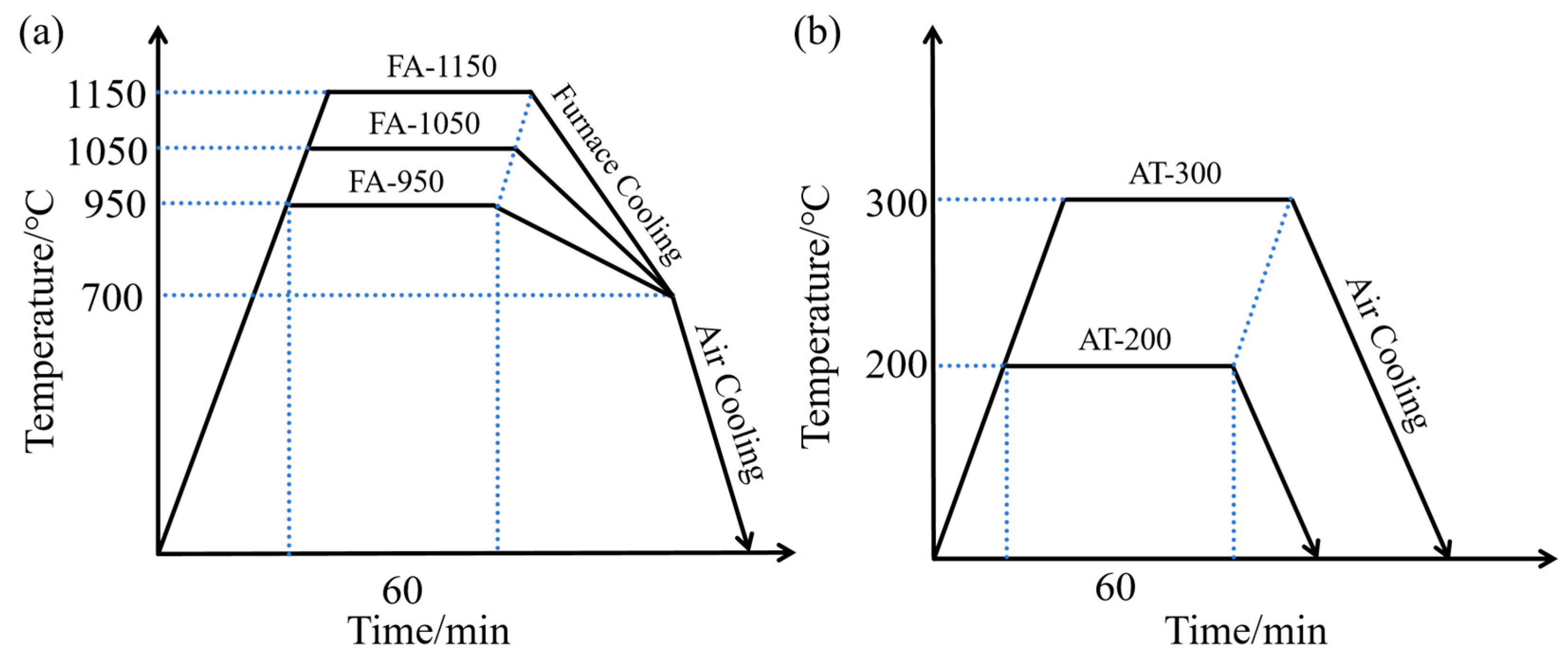
2.1. Preparation and Heat Treatment
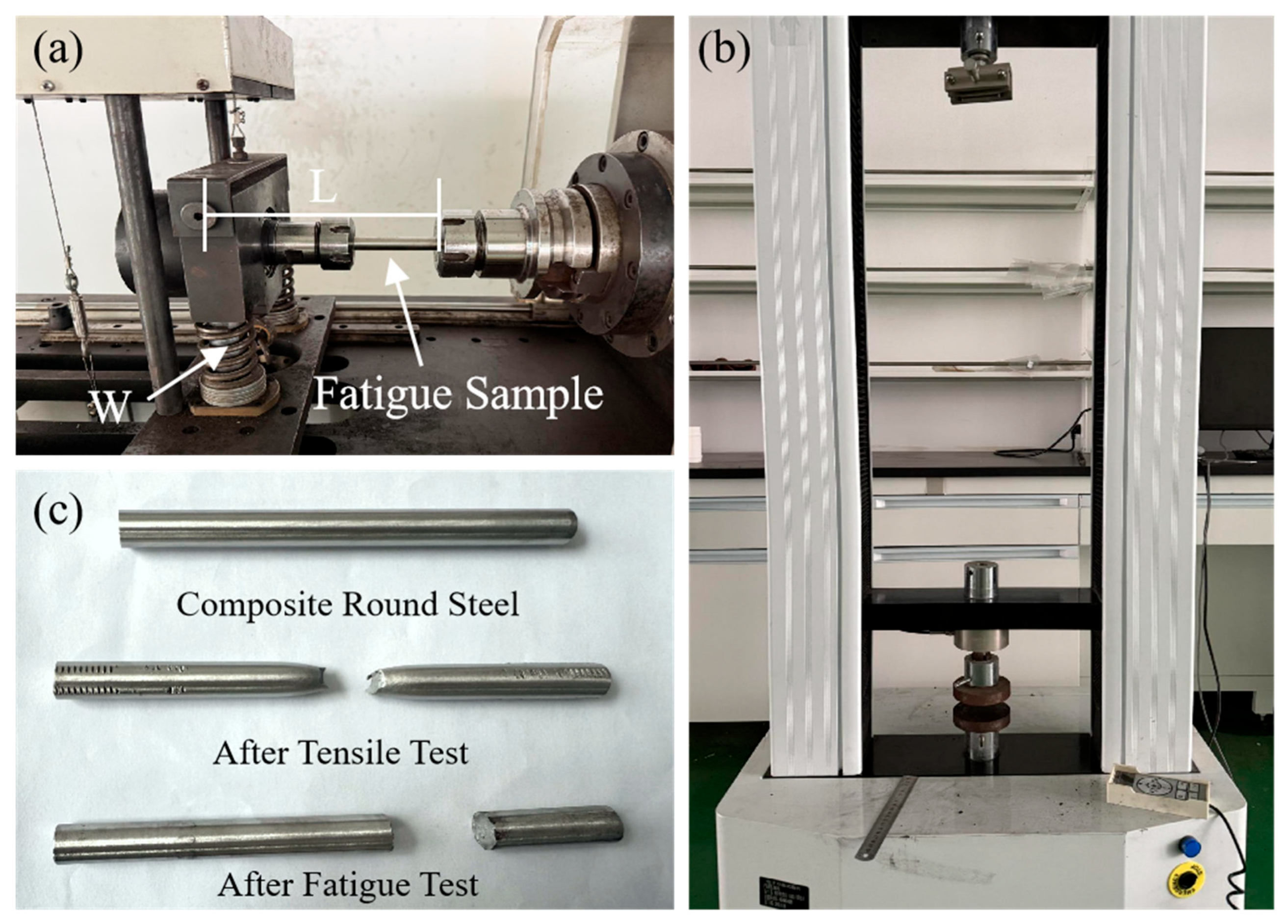
2.2. Characterization of Microstructure and Properties of Composites
3. Results and Discussion
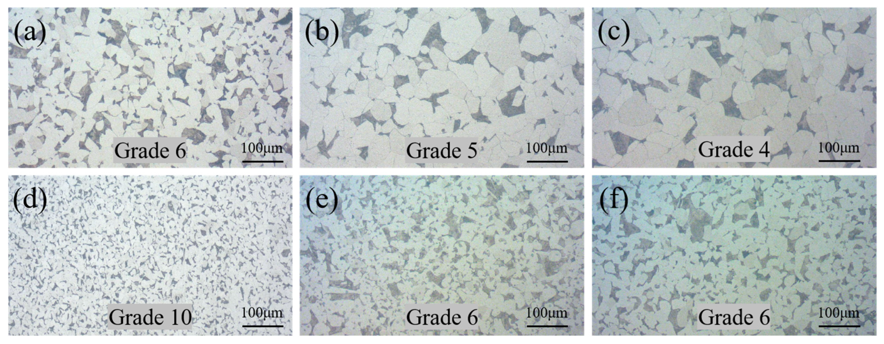
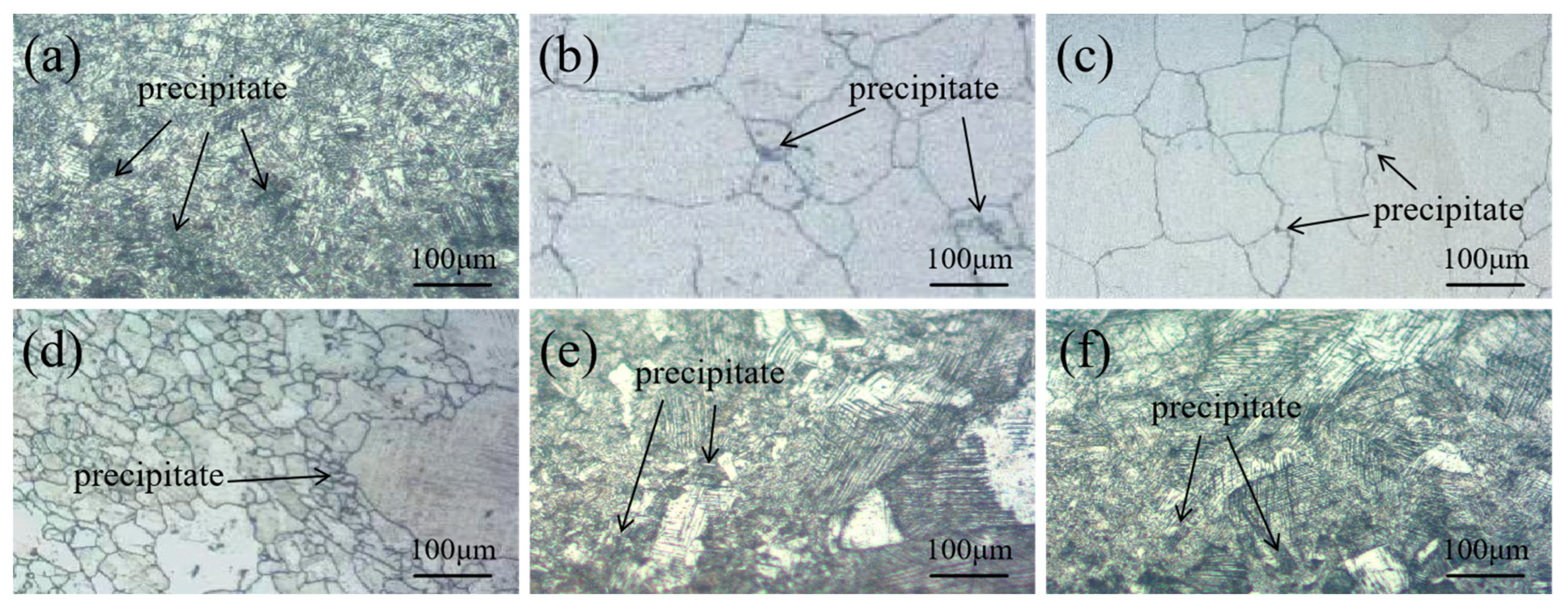
3.1. Microstructure and Mechanical Properties
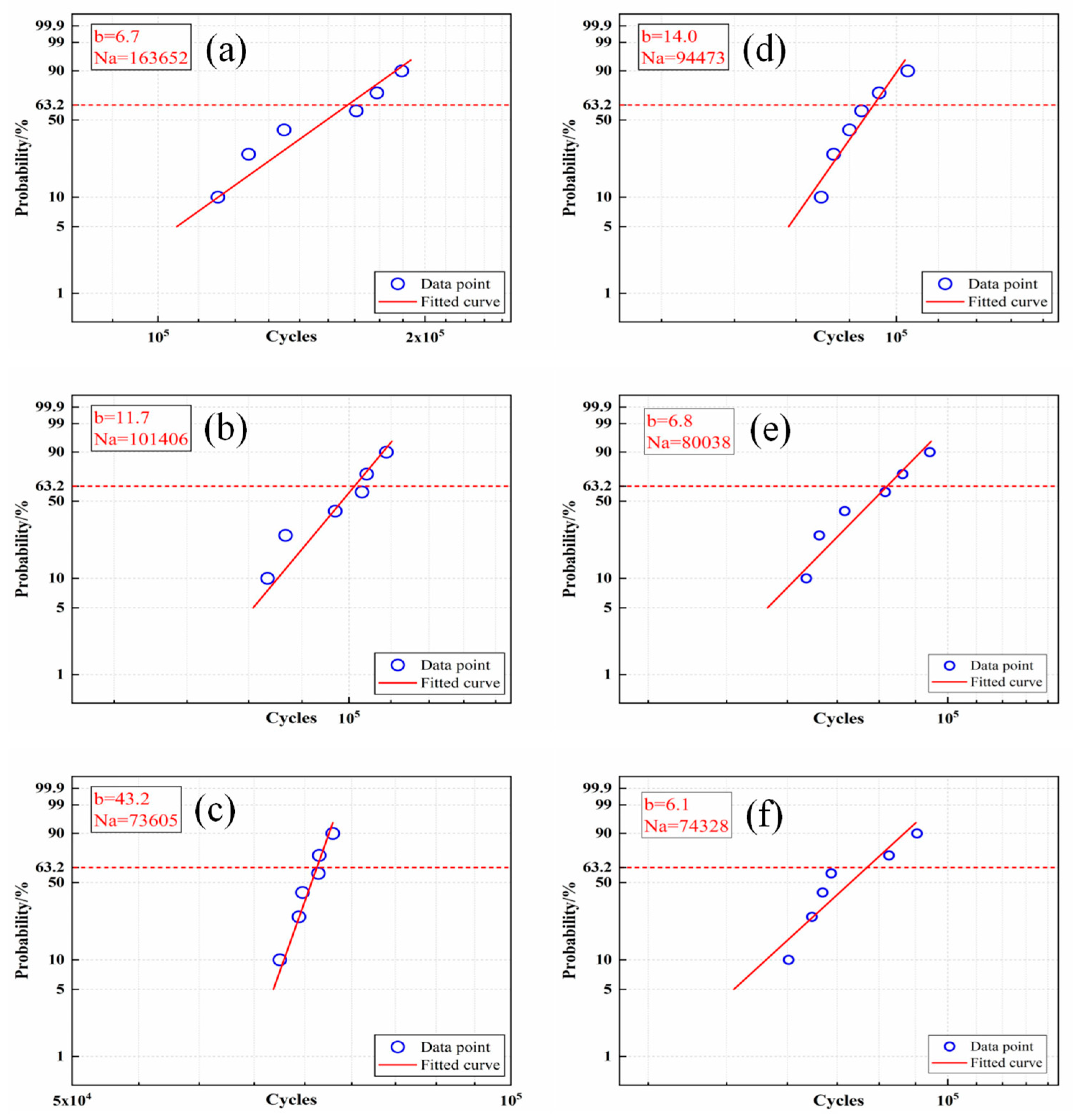
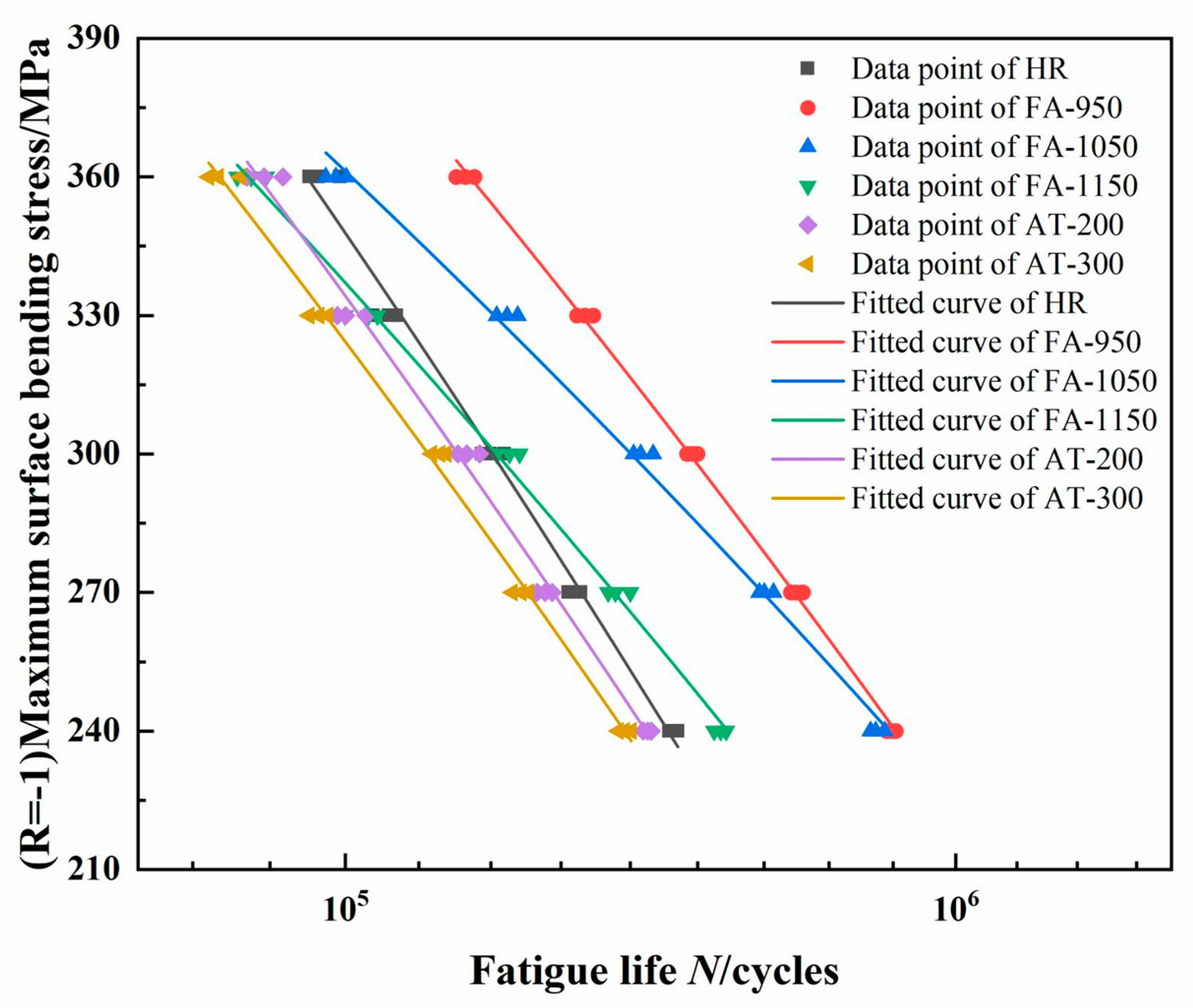
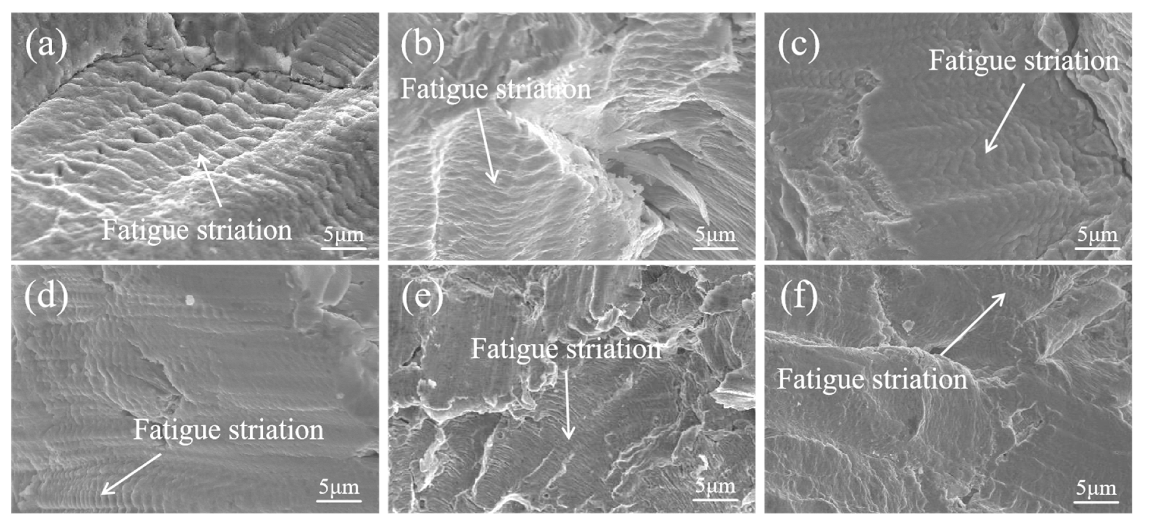
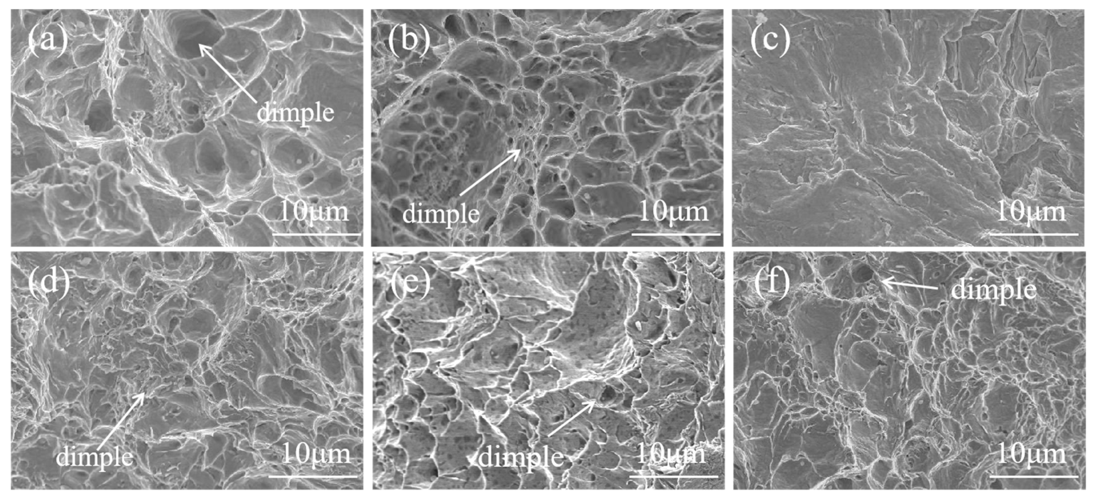
3.2. Fatigue Properties
3.3. Corrosion Resistance
4. Conclusions
Author Contributions
Funding
Institutional Review Board Statement
Informed Consent Statement
Data Availability Statement
Conflicts of Interest
References
- Mutlu, I.H.; Emre, M.C.; Kaya, A.O. A comparison of the corrosion resistance of galvanized low steel with solgel method coated ZrO2, ZrO2+Polymer coating. Kuwait J. Sci. 2023, 50, 524–538. [Google Scholar] [CrossRef]
- Lu, J.Z.; Deng, W.W.; Luo, K.Y.; Wu, L.J.; Lu, H.F. Surface EBSD analysis and strengthening mechanism of AISI304 stainless steel subjected to massive LSP treatment with different pulse energies. Mater. Charact. 2017, 125, 99–107. [Google Scholar] [CrossRef]
- Xu, W.; Yang, Y.; Dai, C.; Xie, J. Optimization of spinning parameters of 20/316L bimetal composite tube based on orthogonal test. Sci. Eng. Compos. Mater. 2020, 27, 272–279. [Google Scholar] [CrossRef]
- Wang, S.; Zhao, G.; Li, Y.; Li, J.; Song, Y. Composite Plate Rolling Technology of 304/Q345R Based on a Corrugated Interface. Materials 2019, 12, 3866. [Google Scholar] [CrossRef]
- Wang, J.; Zhao, F.; Xie, G.; Hou, Y.; Wang, R.; Liu, X. Rolling deformation behaviour and interface evaluation of Cu-Al bimetallic composite plates fabricated by horizontal continuous composite casting. J. Mater. Process. Technol. 2021, 298, 117296. [Google Scholar] [CrossRef]
- Jiang, W.; Fan, Z.; Li, G.; Li, C. Effects of zinc coating on interfacial microstructures and mechanical properties of aluminum/steel bimetallic composites. J. Alloys Compd. 2016, 678, 249–257. [Google Scholar] [CrossRef]
- Abdelkader, W.B.; Bahloul, R.; Arfa, H. Numerical investigation of the influence of some parameters in SPIF process on the forming forces and thickness distributions of a bimetallic sheet CP-titanium/low-carbon steel compared to an individual layer. Procedia Manuf. 2020, 47, 1319–1327. [Google Scholar] [CrossRef]
- Li, Z.; Xie, H.; Jia, F.; Lu, Y.; Yuan, X.; Jiao, S.; Jiang, Z. Study on Deformation Characteristics and Microstructure Evolution of 2205/AH36 Bimetal Composite in a Novel Hot Forming Process. Metals 2020, 10, 1375. [Google Scholar] [CrossRef]
- Li, H.; Zhang, L.; Zhang, B.; Zhang, Q. Effect of heat treatment on the microstructure and corrosion resistance of stainless/carbon steel bimetal plate. Adv. Mater. Sci. Eng. 2020, 2020, 1280761. [Google Scholar] [CrossRef]
- Huang, Q.; Yang, X.; Ma, L.; Zhou, C.; Guang, M.; Li, H. Interface-correlated characteristics of stainless steel/carbon steel plate fabricated by AAWIV and hot rolling. J. Iron Steel Res. Int. 2014, 21, 931–937. [Google Scholar] [CrossRef]
- Kaya, Y.; Kahraman, N.; Durgutlu, A.; Gülenç, B. Investigation of the microstructural, mechanical and corrosion properties of grade a ship steel-duplex stainless steel composites produced via explosive welding. Metall. Mater. Trans. A 2017, 48, 3721–3733. [Google Scholar] [CrossRef]
- Su, H.; Luo, X.; Chai, F.; Shen, J.; Sun, X.; Lu, F. Manufacturing technology and application trends of titanium clad steel plates. J. Iron Steel Res. Int. 2015, 22, 977–982. [Google Scholar] [CrossRef]
- Tan, J.; Gao, Z.; Ren, S.; Xu, Q.; Wang, K.; Zeng, Q. Improving the microstructures and mechanical properties of U71Mn rail steel liner friction welded joint by normalizing treatment. Mater. Today Commun. 2024, 38, 107736. [Google Scholar] [CrossRef]
- Sarkar, A.; Modak, P.; Mandal, A.; Chakrabarti, D.; Karmakar, A. Correlation between microstructure and tensile properties of low-carbon steel processed via different thermomechanical routes. J. Mater. Eng. Perform. 2024, 33, 7975–7989. [Google Scholar] [CrossRef]
- Wang, H.; Wang, A.; Li, C.; Yu, X.; Xie, J.; Liu, C. Effect of secondary-phase precipitation on mechanical properties and corrosion resistance of 00cr27ni7mo5n hyper-duplex stainless steel during solution treatment. Materials 2022, 15, 7533. [Google Scholar] [CrossRef]
- Wang, J.; Shi, W.; Xiang, S.; Ballinger, R.G. Study of the corrosion behaviour of sensitized 904L austenitic stainless steel in Cl-solution. Corros. Sci. 2021, 181, 109234. [Google Scholar] [CrossRef]
- Ding, B.; Zhao, Y.; Huang, Z.; Cai, L.; Wang, N. Tensile bearing capacity for bolted spherical joints with different screwing depths of high-strength bolts. Eng. Struct. 2020, 225, 111255. [Google Scholar] [CrossRef]
- Dhib, Z.; Guermazi, N.; Gaspérini, M.; Haddar, N. Cladding of low-carbon steel to austenitic stainless steel by hot-roll bonding: Microstructure and mechanical properties before and after welding. Mater. Sci. Eng. A 2016, 656, 130–141. [Google Scholar] [CrossRef]
- Yang, L.; Wang, Y.; Guan, J.; Zhang, Y.; Shi, Y. Bearing strength of stainless steel bolted connections. Adv. Struct. Eng. 2015, 18, 1051–1062. [Google Scholar] [CrossRef]
- Salman, O.O.; Gammer, C.; Chaubey, A.K.; Eckert, J.; Scudino, S. Effect of heat treatment on microstructure and mechanical properties of 316L steel synthesized by selective laser melting. Mater. Sci. Eng. A 2019, 748, 205–212. [Google Scholar] [CrossRef]
- Zhao, B.; Xie, L.; Song, J.; Ren, J.; Wang, B.; Zhang, S. Fatigue life prediction of aero-engine compressor disk based on a new stress field intensity approach. Int. J. Mech. Sci. 2020, 165, 105190. [Google Scholar] [CrossRef]
- Li, G.; Wang, S.; He, J.; Wu, K.; Zhou, C. Compilation of load spectrum of machining center spindle and application in fatigue life prediction. J. Mech. Sci. Technol. 2019, 33, 1603–1613. [Google Scholar] [CrossRef]
- Yang, Y.; Jiang, Z.; Chen, Y.; Liu, X.; Sun, J.; Wang, W. Interfacial microstructure and strengthening mechanism of stainless steel/carbon steel laminated composite fabricated by liquid-solid bonding and hot rolling. Mater. Charact. 2022, 191, 112122. [Google Scholar] [CrossRef]
- Qi, X.; Huan, P.; Wang, X.; Shen, X.; Liu, Z.; Di, H. Effect of microstructure homogeneity on the impact fracture mechanism of X100 pipeline steel laser–MAG hybrid welds with an alternating magnetic field. Mater. Sci. Eng. A 2022, 851, 143656. [Google Scholar] [CrossRef]
- Wu, B.; Guo, K.; Yang, X.; Gao, Y.; Jin, Y.; Gao, Y.; Wang, Q.; Zhang, F. Effect of carbon content of substrate on the microstructure changes and tensile behavior of clad layer of stainless steel composites. Mater. Sci. Eng. A 2022, 831, 142201. [Google Scholar] [CrossRef]
- Huang, X.; Wang, D.; Yang, Y. Effect of precipitation on intergranular corrosion resistance of 430 ferritic stainless steel. J. Iron Steel Res. Int. 2015, 22, 1062–1068. [Google Scholar] [CrossRef]
- Zhou, Z.; Ding, Y. A study on the fatigue performance and corrosion resistance of 304/45 bimetallic composite bolts. Materials 2023, 16, 4454. [Google Scholar] [CrossRef]
- Kina, A.Y.; Souza, V.M.D.; Tavares, S.S.M.; Souza, J.A.D.; de Abreu, H.F.G. Influence of heat treatments on the intergranular corrosion resistance of the AISI 347 cast and weld metal for high temperature services. J. Mater. Process. Technol. 2008, 199, 391–395. [Google Scholar] [CrossRef]
- Kaneko, K.; Fukunaga, T.; Yamada, K.; Nakada, N.; Kikuchi, M.; Saghi, Z.; Barnard, J.S.; Midgley, P.A. Formation of M23C6-type precipitates and chromium-depleted zones in austenite stainless steel. Scr. Mater. 2011, 65, 509–512. [Google Scholar] [CrossRef]
- Mohammadi, F.; Nickchi, T.; Attar, M.M.; Alfantazi, A. EIS study of potentiostatically formed passive film on 304 stainless steel. Electrochim. Acta 2011, 56, 8727–8733. [Google Scholar] [CrossRef]
- Hang, P.; Zhao, B.; Zhou, J.; Ding, Y. Effect of Heat Treatment on Crevice Corrosion Behavior of 304 Stainless Steel Clad Plate in Seawater Environment. Materials 2023, 16, 3952. [Google Scholar] [CrossRef] [PubMed]
- Li, L.; Zhao, B.; Chen, Y.; Ding, Y. Effect of Heat Treatment on Microstructure and Properties Evolution of Stainless Steel Cladding Plate. Materials 2023, 16, 4809. [Google Scholar] [CrossRef] [PubMed]

| Materials | Cr | Ni | C | Mn | Si | P | S | Fe |
|---|---|---|---|---|---|---|---|---|
| Q235 carbon steel | - | - | 0.22 | 1.4 | 0.35 | 0.045 | 0.045 | balance |
| 304 stainless steel | 18.18 | 8.18 | 0.057 | 0.73 | 0.39 | 0.026 | 0.006 | balance |
| Spectrogram | Fe | C | Cr | Ni |
|---|---|---|---|---|
| 1 | 41.32 | 12.89 | 40.89 | 4.90 |
| 2 | 63.49 | 9.00 | 15.96 | 11.55 |
| 3 | 58.03 | 10.68 | 22.17 | 9.12 |
| Samples | 1# | 2# | 3# | 4# | 5# | 6# | Average |
|---|---|---|---|---|---|---|---|
| FA-950 | 116,825 | 138,762 | 188,356 | 126,546 | 167,347 | 176,548 | 152,397 |
| FA-1050 | 103,321 | 104,542 | 109,843 | 85,321 | 81,569 | 96,626 | 96,870 |
| FA-1150 | 73,780 | 71,543 | 69,423 | 75,483 | 73,875 | 71,952 | 72,676 |
| HR | 85,467 | 95,782 | 102,895 | 88,935 | 91,654 | 82,856 | 91,265 |
| AT-200 | 62,434 | 75,943 | 93,654 | 71,764 | 68,534 | 80,930 | 75,543 |
| AT-300 | 59,789 | 66,198 | 89,351 | 63,764 | 65,234 | 70,223 | 69,093 |
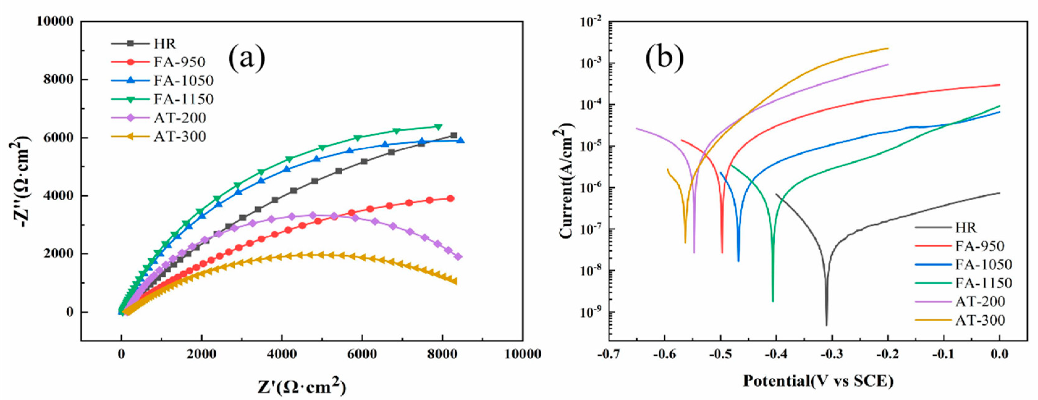
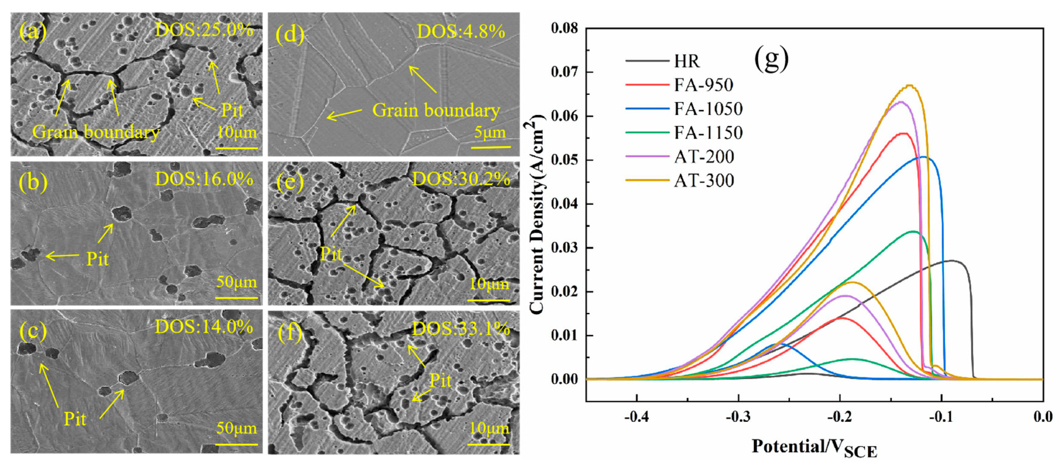
| Sample | FA-950 | F5-1050 | FA-1150 | HR | AT-200 | AT-300 |
|---|---|---|---|---|---|---|
| Ecorr(V) | −0.50 | −0.47 | −0.41 | −0.31 | −0.55 | −0.56 |
| Icorr(A/cm2) | 8.2 × 10⁻⁶ | 1.2 × 10⁻⁶ | 7.4 × 10⁻⁷ | 5.4 × 10⁻⁸ | 8.4 × 10⁻⁶ | 7.2 × 10⁻⁶ |
| Rf(Ω·cm2) | 1.5 × 10⁴ | 1.6 × 10⁴ | 1.7 × 10⁴ | 2.6 × 10⁴ | 1.3 × 10⁴ | 9.6 × 10³ |
| Ir(mA/cm2) | 14.0 | 8.1 | 4.7 | 1.3 | 19.1 | 22.2 |
| Ia(mA/cm2) | 56.1 | 50.7 | 33.7 | 27.1 | 63.2 | 67.0 |
| DOS(Ir/Ia) × 100% | 25.0 | 16.0 | 14.0 | 4.8 | 30.2 | 33.1 |
Disclaimer/Publisher’s Note: The statements, opinions and data contained in all publications are solely those of the individual author(s) and contributor(s) and not of MDPI and/or the editor(s). MDPI and/or the editor(s) disclaim responsibility for any injury to people or property resulting from any ideas, methods, instructions or products referred to in the content. |
© 2025 by the authors. Licensee MDPI, Basel, Switzerland. This article is an open access article distributed under the terms and conditions of the Creative Commons Attribution (CC BY) license (https://creativecommons.org/licenses/by/4.0/).
Share and Cite
Zheng, X.; Ding, Y. Effect of Heat Treatment on Microstructure and Properties of 304/Q235 Composite Round Steel. Materials 2025, 18, 2497. https://doi.org/10.3390/ma18112497
Zheng X, Ding Y. Effect of Heat Treatment on Microstructure and Properties of 304/Q235 Composite Round Steel. Materials. 2025; 18(11):2497. https://doi.org/10.3390/ma18112497
Chicago/Turabian StyleZheng, Xiexin, and Yi Ding. 2025. "Effect of Heat Treatment on Microstructure and Properties of 304/Q235 Composite Round Steel" Materials 18, no. 11: 2497. https://doi.org/10.3390/ma18112497
APA StyleZheng, X., & Ding, Y. (2025). Effect of Heat Treatment on Microstructure and Properties of 304/Q235 Composite Round Steel. Materials, 18(11), 2497. https://doi.org/10.3390/ma18112497