
Effect of Si Addition on Structure and Corrosion Resistance of FeCoNiCr High-Entropy Alloy Coating

Highlights
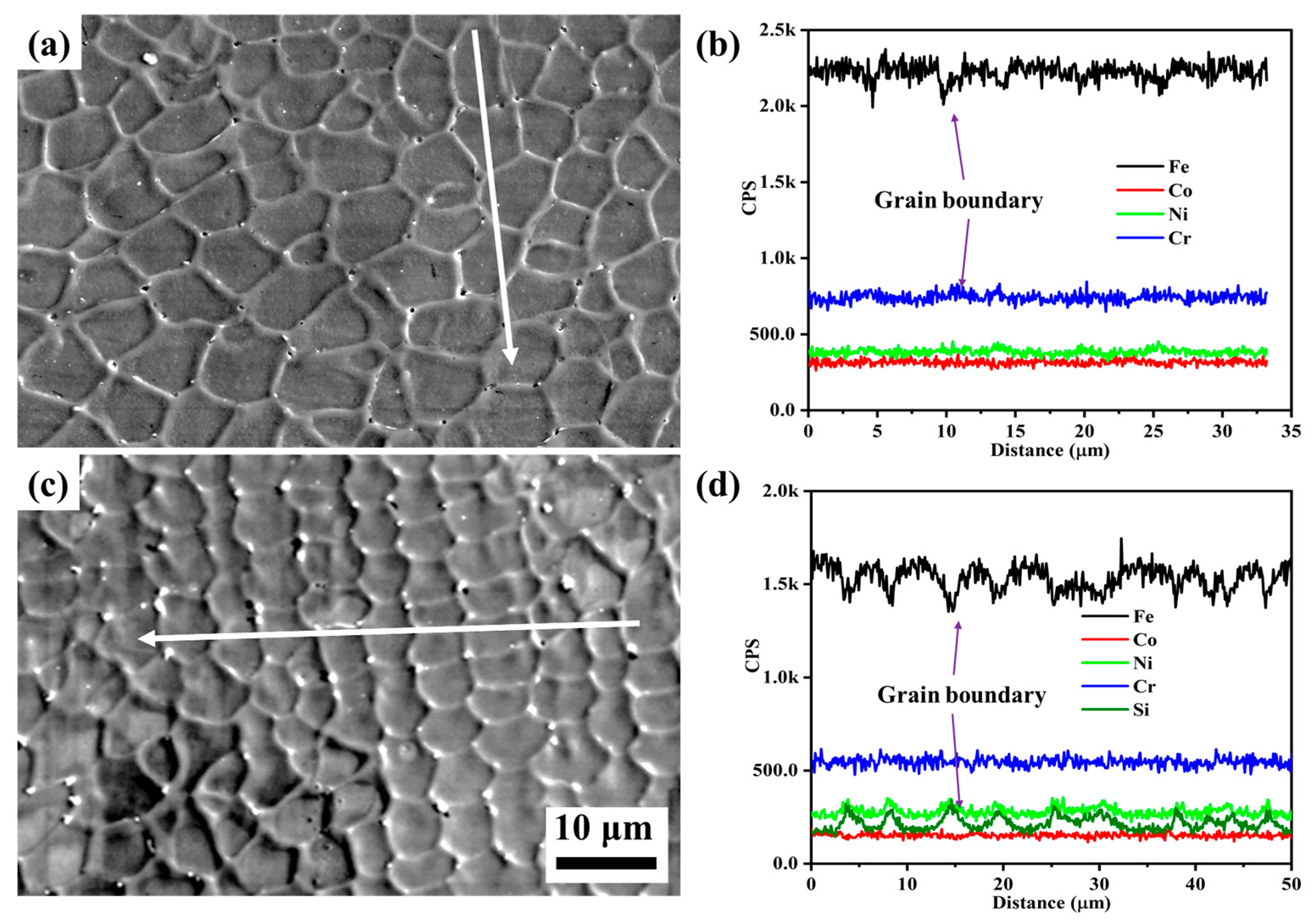
- The addition of Si results in its concentration at the grain boundaries, effectively impeding grain growth and refining the grain size of the coating.
- As the Si content increases, a transition occurs from an FCC structure to an FCC+BCC structure.
- The Si4 coating exhibits exceptional corrosion resistance, while maintaining low production costs.
Abstract
1. Introduction
2. Experimental Section
2.1. Sample Preparation
2.2. Analysis and Characterization Methods
3. Results and Discussion
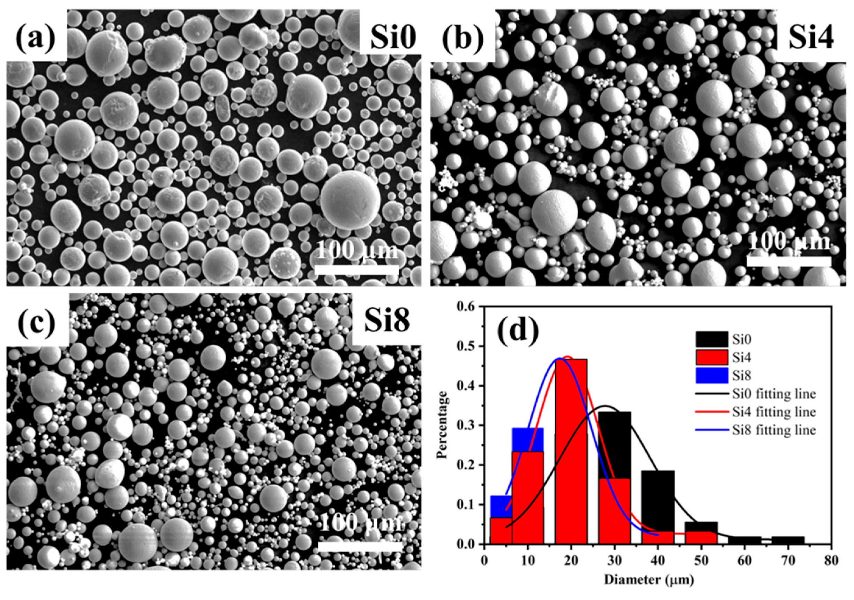
3.1. Microstructure and Phase Analysis of the Powder
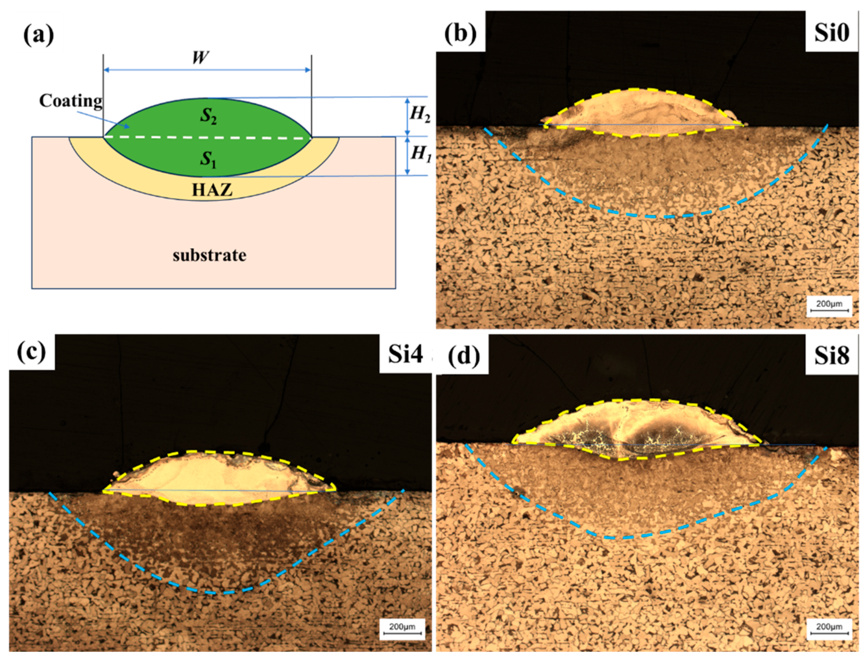
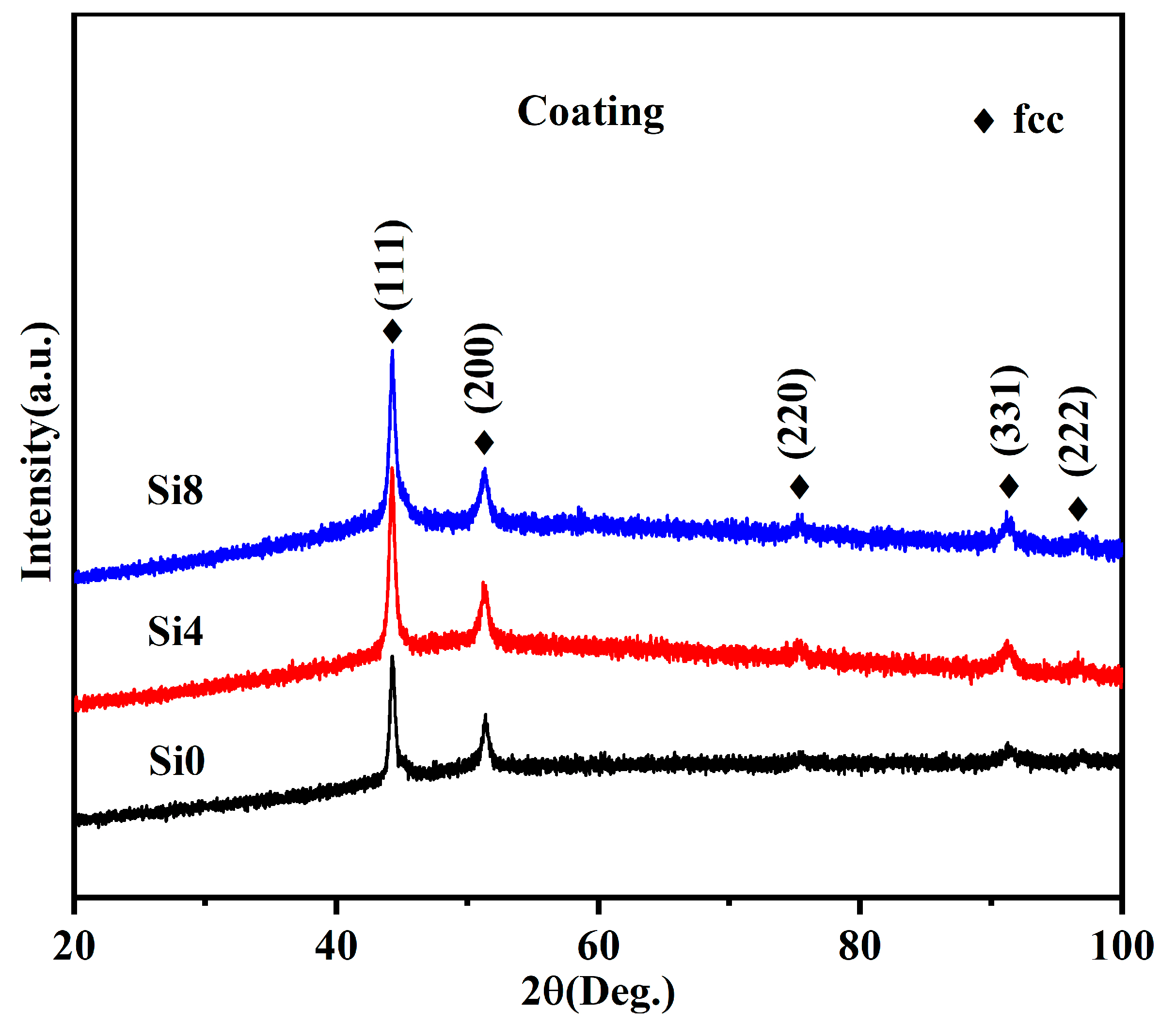
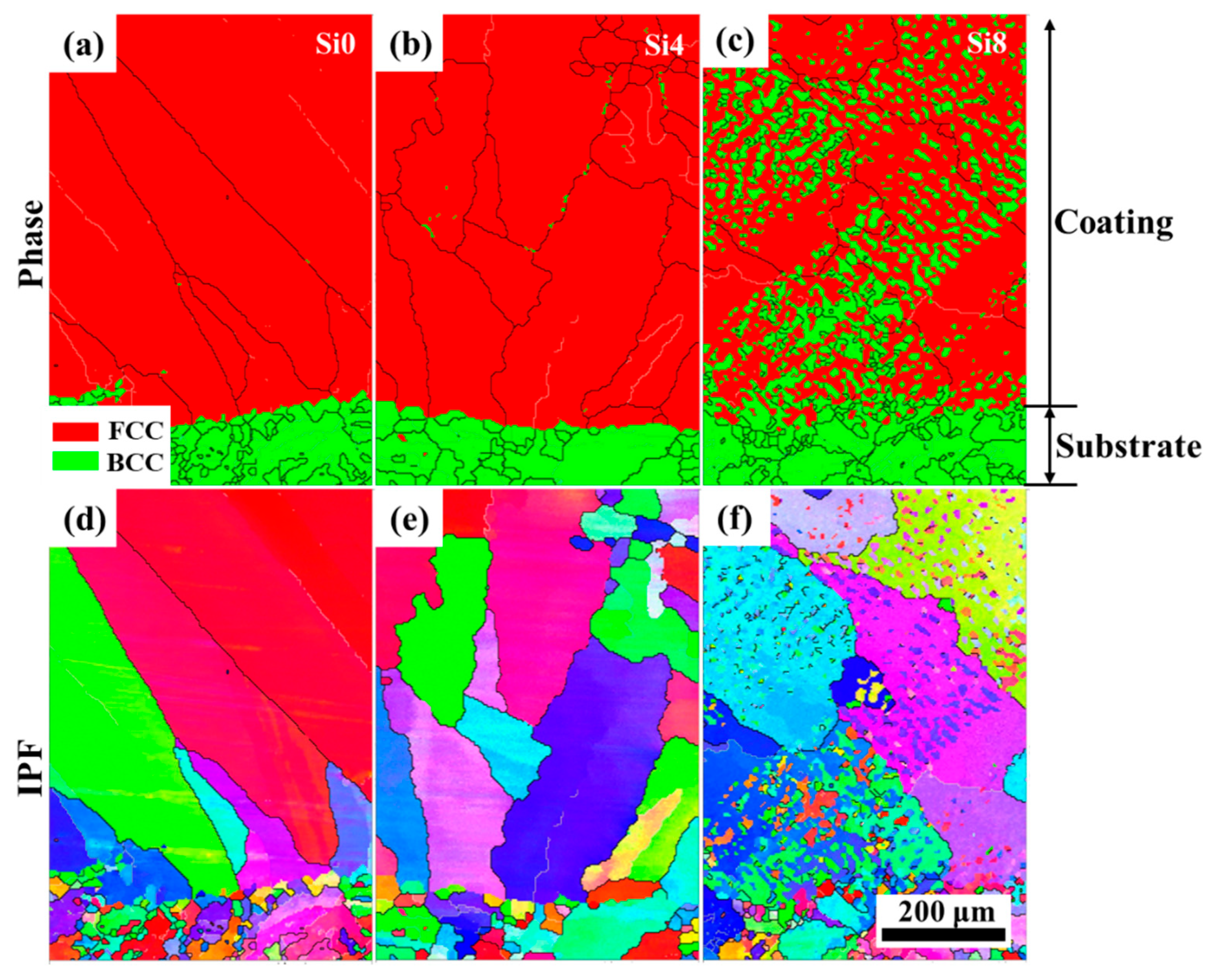
3.2. Microstructure and Structural Analysis of the Coating
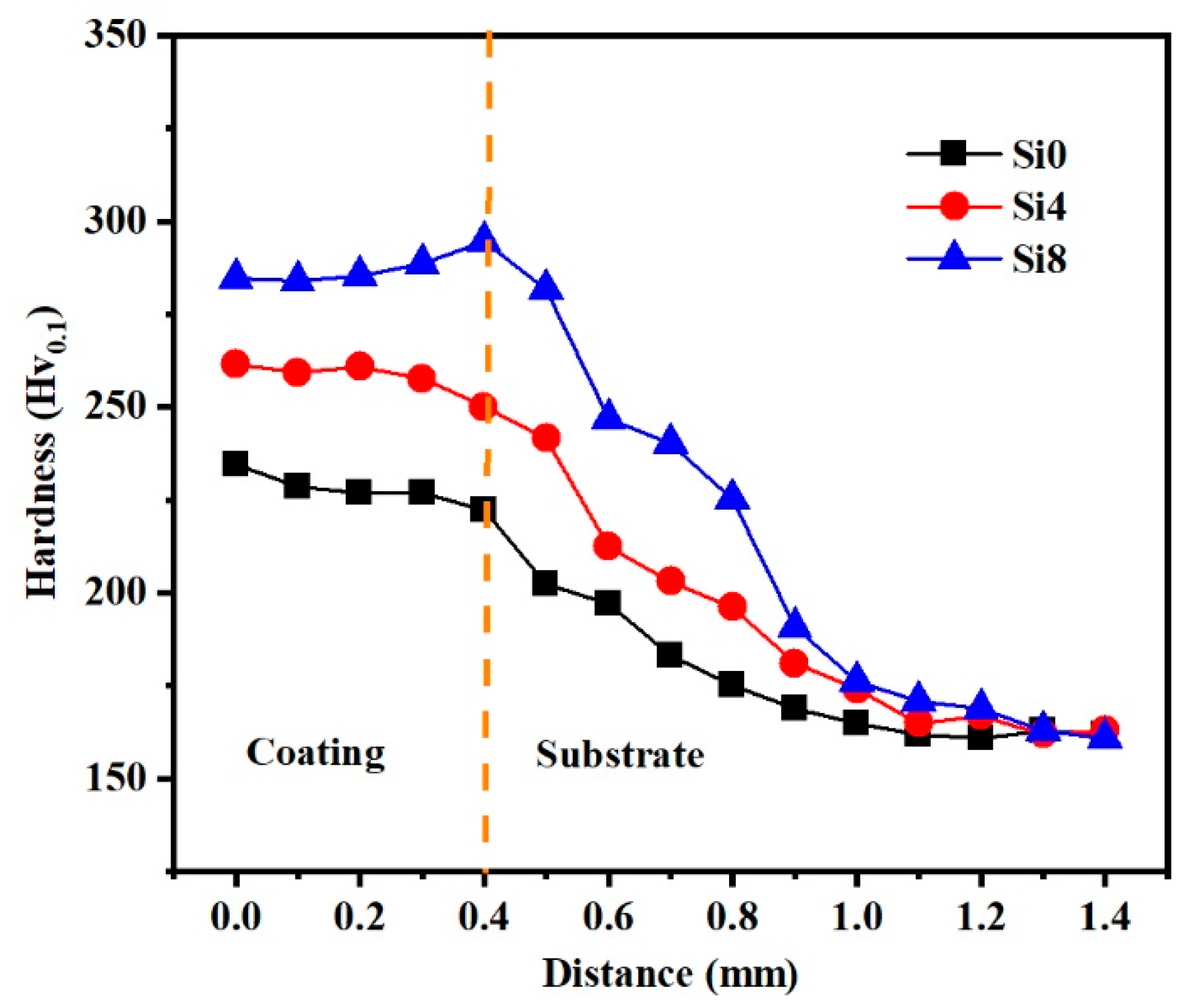
3.3. Microhardness
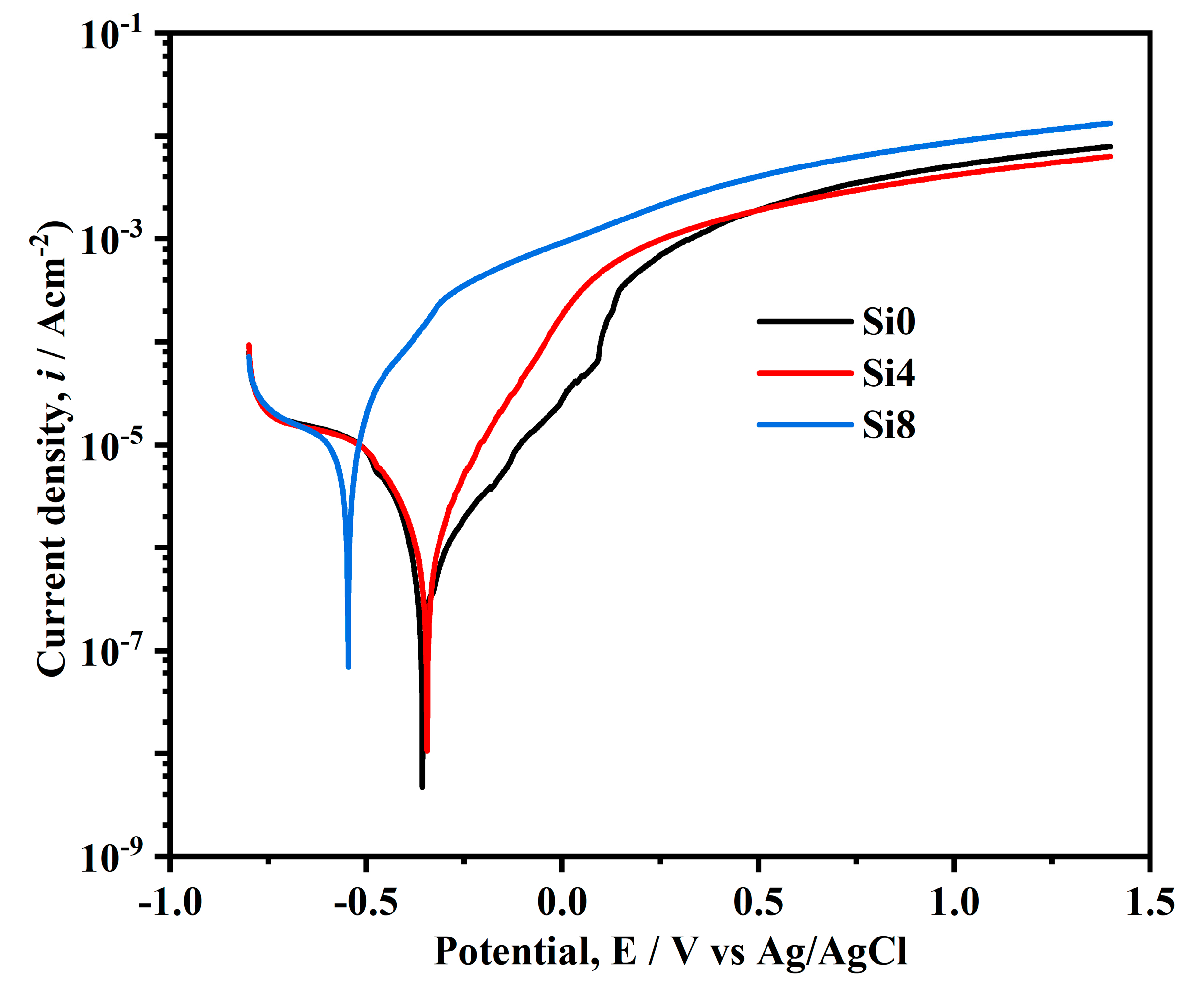
3.4. Corrosion Behaviors
4. Conclusions
- Si addition enhances the powder’s fluidity during melting, leading to improved bonding with the substrate.
- Si addition leads to its enrichment at grain boundaries, hindering grain growth and refining the grain size of the coating.
- For the studied coatings, all samples exhibit an FCC structure, with only minor BCC phases at grain boundaries. At the coating–substrate interface, increasing Si content results in a transition from a single-phase FCC to an FCC + BCC structure.
- The Si4 coating demonstrates superior corrosion resistance, attributed to the Si-enhanced enrichment of corrosion-resistant elements at grain boundaries. This enrichment stabilizes the passivation film, effectively improving corrosion resistance while maintaining low production costs.
Author Contributions
Funding
Institutional Review Board Statement
Informed Consent Statement
Data Availability Statement
Acknowledgments
Conflicts of Interest
References
- George, E.P.; Raabe, D.; Ritchie, R.O. High-entropy alloys. Nat. Rev. Mater. 2019, 4, 515–534. [Google Scholar] [CrossRef]
- Li, W.D.; Xie, D.; Li, D.Y.; Zhang, Y.; Gao, Y.F.; Liaw, P.K. Mechanical behavior of high-entropy alloys. Prog. Mater. Sci. 2021, 118, 100777. [Google Scholar] [CrossRef]
- Liu, C.; Gao, Y.; Chong, K.; Guo, F.Q.; Wu, D.T.; Zou, Y. Effect of Nb content on the microstructure and corrosion resistance of FeCoCrNiNbx high-entropy alloys in chloride ion environment. J. Alloys Compd. 2023, 935, 168013. [Google Scholar] [CrossRef]
- Yin, B.L.; Maresca, F.; Curtin, W.A. Vanadium is an optimal element for strengthening in both fcc and bcc high-entropy alloys. Acta Mater. 2020, 188, 486–491. [Google Scholar] [CrossRef]
- Xiao, D.H.; Zhou, P.F.; Wu, W.Q.; Diao, H.Y.; Gao, M.C.; Song, M.; Liaw, P.K. Microstructure, mechanical and corrosion behaviors of AlCoCuFeNi-(Cr,Ti) high entropy alloys. Mater. Des. 2017, 116, 438–447. [Google Scholar] [CrossRef]
- Shi, Z.L.; Liu, Y.Z.; Zhang, H.R.; Li, C.Z.; Chen, S.N.; Yang, Y.J.; Liang, S.X.; Ma, M.Z. Synergistic strength-ductility enhancement of CoCrFeNi high-entropy alloys with regulated Co/Cr atomic ratios. Mat. Sci. Eng. A 2024, 912, 146995. [Google Scholar] [CrossRef]
- Zhu, L.D.; Xue, P.S.; Lan, Q.; Meng, G.; Ren, Y.; Yang, Z.C.; Xu, P.H.; Liu, Z. Recent research and development status of laser cladding: A review. Opt. Laser Technol. 2021, 138, 106915. [Google Scholar] [CrossRef]
- Liang, Y.; Liao, Z.; Zhang, L.; Cai, M.; Wei, X.; Shen, J. A review on coatings deposited by extreme high-speed laser cladding: Processes, materials, and properties. Opt. Laser Technol. 2023, 164, 109472. [Google Scholar] [CrossRef]
- Arif, Z.U.; Khalid, M.Y.; Rehman, E.U.; Ullah, S.; Atif, M.; Tariq, A. A review on laser cladding of high-entropy alloys, their recent trends and potential applications. J. Manuf. Process 2021, 68, 225–273. [Google Scholar] [CrossRef]
- Liu, H.; Yang, D.; Jiang, Q.; Jiang, Y.; Yang, W.; Liu, L.; Zhang, L.-C. Additive manufacturing of metallic glasses and high-entropy alloys: Significance, unsettled issues, and future directions. J. Mater. Sci. Technol. 2023, 140, 79–120. [Google Scholar] [CrossRef]
- Xiao, J.K.; Tan, H.; Wu, Y.Q.; Chen, J.; Zhang, C. Microstructure and wear behavior of FeCoNiCrMn high entropy alloy coating deposited by plasma spraying. Surf. Coat. Technol. 2020, 385, 125430. [Google Scholar] [CrossRef]
- Zendejas, M.L.; Riekehr, L.; Jansson, U. Phase formation in magnetron sputtered CrMnFeCoNi high entropy alloy. Surf. Coat. Technol. 2020, 403, 126323. [Google Scholar] [CrossRef]
- Liu, Z.; Liu, G.; Miao, X.; Sun, L.; Han, Z.; Zhang, G. Microstructure and wear-resistance of the CoCrFeNiMo high entropy alloy coatings by modulated arc currents using plasma transferred arc weld technique. Intermetallics 2024, 175, 108506. [Google Scholar] [CrossRef]
- Tanigawa, D.; Abe, N.; Tsukamoto, M.; Hayashi, Y.; Yamazaki, H.; Tatsumi, Y.; Yoneyama, M. The effect of particle size on the heat affected zone during laser cladding of Ni–Cr–Si–B alloy on C45 carbon steel. Opt. Laser Eng. 2018, 101, 23–27. [Google Scholar] [CrossRef]
- Li, J.C.; Huang, Y.X.; Meng, X.C.; Xie, Y.M. A review on high entropy alloys coatings: Fabrication processes and property assessment. Adv. Eng. Mater. 2019, 21, 1900343. [Google Scholar] [CrossRef]
- Bae, J.W.; Seol, J.B.; Moon, J.; Sohn, S.S.; Jang, M.J.; Um, H.Y.; Lee, B.J.; Kim, H.S. Exceptional phase-transformation strengthening of ferrous medium-entropy alloys at cryogenic temperatures. Acta Mater. 2018, 161, 388–399. [Google Scholar] [CrossRef]
- Zhang, K.S.; Zhang, X.H.; Zhang, E.; Wei, R.; Wang, L.L.; Chen, J.L.; Yuan, S.H.; Han, Z.H.; Chen, C.; Li, F.S. Strengthening of ferrous medium entropy alloys by promoting phase transformation. Intermetallics 2021, 136, 107265. [Google Scholar] [CrossRef]
- Han, Z.H.; Li, J.Z.; Tian, Y.; Tian, A.L.; Sun, A.R.; Wei, R.; Liu, G. Annealing-induced abnormally ultrahigh cryogenic strength-ductility synergy in a cold rolled ferrous medium entropy alloy. Intermetallics 2023, 159, 107933. [Google Scholar] [CrossRef]
- Dong, M.L.; Liu, P.W.; Wang, C.H.; Wang, Y.H.; Tang, X.Y.; He, M.X.; Liu, J.Q. Microstructure and properties of FeCoNiCr and FeCoNiCrW high entropy alloy coatings by electro-deposition. Intermetallics 2024, 175, 108492. [Google Scholar] [CrossRef]
- Rong, Z.Y.; Wang, C.H.; Wang, Y.; Dong, M.L.; You, Y.; Wang, J.N.; Liu, H.N.; Liu, J.Q.; Wang, Y.H.; Zhu, Z.Y. Microstructure and properties of FeCoNiCrX (X Mn, Al) high-entropy alloy coatings. J. Alloys Compd. 2022, 921, 166061. [Google Scholar] [CrossRef]
- Kong, L.C.; Shi, C.W.; Hao, X.; Wang, S.H.; Huo, Y.S.; Zhu, Z.H.; Sun, J.H. Effect of Ti and Mo content changes on microstructure and properties of laser cladding FeCoCrNiMn high entropy alloy coatings. Intermetallics 2024, 175, 108509. [Google Scholar] [CrossRef]
- Chaudhary, V.; Soni, V.; Gwalani, B.; Ramanujan, R.V.; Banerjee, R. Influence of non-magnetic Cu on enhancing the low temperature magnetic properties and Curie temperature of FeCoNiCrCu(x) high entropy alloys. Scripta Mater. 2020, 182, 99–103. [Google Scholar] [CrossRef]
- Xu, Z.K.; Hou, Y.H.; Li, G.Q. Atomic-scale investigation of the synergistic impact of Mo and Nb addition on enhancing the performance of laser cladding FeCoCrNi-based high entropy alloy coatings. Surf. Coat. Technol. 2024, 490, 131162. [Google Scholar] [CrossRef]
- Lin, D.Y.; Xu, L.Y.; Li, X.J.; Jing, H.; Qin, G.; Pang, H.; Minami, F. A Si-containing FeCoCrNi high-entropy alloy with high strength and ductility synthesized in situ via selective laser melting. Addit. Manuf. 2020, 35, 101340. [Google Scholar] [CrossRef]
- Cemin, F.; Jimenez, M.; Leidens, L.M.; Figueroa, C.A.; Alvarez, F. A thermodynamic study on phase formation and thermal stability of AlSiTaTiZr high-entropy alloy thin films. J. Alloys Compd. 2020, 838, 155580. [Google Scholar] [CrossRef]
- Moravcik, I.; Cizek, J.; Zapletal, j.; Kovacova, Z.; Vesely, J.; Minarik, P.; Kitzmantel, M.; Neubauer, E.; Dlouhy, I. Microstructure and mechanical properties of Ni1.5Co1.5CrFeTi0.5 high entropy alloy fabricated by mechanical alloying and spark plasma sintering. Mater. Des. 2017, 119, 141–150. [Google Scholar] [CrossRef]
- Yang, X.; Zhang, Y. Prediction of high-entropy stabilized solid-solution in multi-component alloys. Mater. Chem. Phys. 2012, 132, 233–238. [Google Scholar] [CrossRef]
- Kumar, J.; Linda, A.; Sadhasivam, M.; Pradeep, K.G.; Gurao, N.P.; Biswas, K. The effect of Si addition on the structure and mechanical properties of equiatomic CoCrFeMnNi high entropy alloy by experiment and simulation. Materialia 2023, 27, 101707. [Google Scholar] [CrossRef]
- Wei, D.X.; Gong, W.; Tsuru, T.; Lobzenko, I.; Li, X.; Harjo, S.; Kawasaki, T.; Do, H.-S.; Bae, J.W.; Wagner, C.; et al. Si-addition contributes to overcoming the strength-ductility trade-off in high-entropy alloys. Int. J. Plast. 2022, 159, 103443. [Google Scholar] [CrossRef]
- Nagarjuna, C.; Lee, H.; Dewangan, S.K.; Rao, K.P.; Pillai, G.M.; Kumar, V.; Ahn, B. Understanding the role of Si alloying on the structural, mechanical, wear and high temperature oxidation behavior of CrFeNiTiX (X=Si) high entropy alloys. J. Mater. Res. Technol. 2024, 33, 5119–5135. [Google Scholar] [CrossRef]
- Huang, L.; Wang, X.J.; Jia, F.C.; Zhao, X.; Huang, B.; Ma, J.; Wang, C. Effect of Si element on phase transformation and mechanical properties for FeCoCrNiSix high entropy alloys. Mater. Lett. 2021, 282, 128809. [Google Scholar] [CrossRef]
- Gao, Q.Y.; Feng, S.L.; Wei, R.; Chen, W.; Zhu, W.; Li, F. A novel low-cost and ultrahigh strength FeCoNiCrSi ferrous medium-entropy alloy at room and liquid nitrogen temperatures. Mater. Lett. 2022, 328, 133119. [Google Scholar] [CrossRef]
- Lin, T.X.; Feng, M.Y.; Lian, G.F.; Lu, H.; Chen, C.; Huang, X. Effects of Si content on the microstructure and properties of CoCrFeMnNiSix high-entropy alloy coatings by laser cladding. Mater. Charact. 2024, 216, 114246. [Google Scholar] [CrossRef]
- Liu, Y.Y.; Yao, Z.P.; Zhang, P.; Xu, Z.; Lin, S.; He, M.; Lu, S.; Wu, X. Tailoring high-temperature oxidation resistance of FeCrMnVSi high entropy alloy coatings via building Si-rich dendrite microstructure. Appl. Surf. Sci. 2022, 606, 154862. [Google Scholar] [CrossRef]
- Cai, Y.C.; Chen, Y.; Manladan, S.M.; Luo, Z.; Gao, F.; Li, L. Influence of dilution rate on the microstructure and properties of FeCrCoNi high-entropy alloy coating. Mater. Des. 2018, 142, 124–137. [Google Scholar] [CrossRef]
- Mao, C.L.; Liu, C.X.; Yu, L.M.; Li, H.; Liu, Y. Discontinuous lath martensite transformation and its relationship with annealing twin of parent austenite and cooling rate in low carbon RAFM steel. Mater. Des. 2021, 197, 109252. [Google Scholar] [CrossRef]
- Yuan, S.H.; Wu, S.J.; Chen, T.T.; Fu, Q.; Wei, R.; Chen, C.; Wang, T.; Cai, Y.; Li, F. Microstructure and corrosion behavior of Co-free FeCrNiSi0.4 medium entropy alloy coating fabricated by laser cladding. Intermetallics 2023, 162, 108024. [Google Scholar] [CrossRef]
- Yang, H.; Liu, X.S.; Li, A.X.; Li, R.; Xu, S.; Zhang, M.; Yu, P.; Yu, S.; Jiang, M.; Huo, C.; et al. Effect of silicon addition on the corrosion resistance of Al0.2CoCrFe1.5Ni high-entropy alloy in saline solution. J. Alloys Compd. 2023, 964, 171226. [Google Scholar] [CrossRef]
- Zhang, M.D.; Shi, X.L.; Li, Z.Y.; Xu, H.; Li, G. Corrosion behaviors and mechanism of CrFeNi2 based high-entropy alloys. Corros. Sci. 2022, 207, 110562. [Google Scholar] [CrossRef]
- Yu, K.P.; Feng, S.H.; Ding, C.; Yu, P.; Huang, M.X. Improving anti-corrosion properties of CoCrFeMnNi high entropy alloy by introducing Si into nonmetallic inclusions. Corros. Sci. 2022, 208, 110616. [Google Scholar] [CrossRef]
- Liu, H.; Sun, S.F.; Zhang, T.; Zhang, G.; Yang, H.; Hao, J. Effect of Si addition on microstructure and wear behavior of AlCoCrFeNi high-entropy alloy coatings prepared by laser cladding. Surf. Coat. Technol. 2021, 405, 126522. [Google Scholar] [CrossRef]
- Zhu, Z.X.; Liu, X.B.; Liu, Y.F.; Zhang, S.-Y.; Meng, Y.; Zhou, H.-B.; Zhang, S.-H. Effects of Cu/Si on the microstructure and tribological properties of FeCoCrNi high entropy alloy coating by laser cladding. Wear 2023, 512–513, 204533. [Google Scholar] [CrossRef]
- Shi, Z.J.; Wang, Z.B.; Wang, X.D.; Zhang, S.; Zheng, Y.G. Effect of thermally induced B2 phase on the corrosion behavior of an Al0.3CoCrFeNi high entropy alloy. J. Alloys Compd. 2022, 903, 163886. [Google Scholar] [CrossRef]
- Zhang, S.L.; Di, J.; Sun, S.D.; Zhang, B. Microstructure and tribological properties of FeCrCoMnSix high-entropy alloy coatings. Coatings 2024, 14, 1476. [Google Scholar] [CrossRef]


| Elements | C | Si | Mn | S | P | Fe |
|---|---|---|---|---|---|---|
| Content (wt.%) | 0.150 | 0.200 | 0.460 | 0.022 | 0.012 | Balance |
| Element | Purity (wt.%) | Shape | Size |
|---|---|---|---|
| Fe | 99.9% | Block | 3 × 3 mm |
| Co | 99.95% | Block | 5–10 mm |
| Ni | 99.9% | Block | 3 × 3 mm |
| Cr | 99.95% | Block | 1–5 mm |
| Si | 99.999% | Block | 1–6 mm |
Disclaimer/Publisher’s Note: The statements, opinions and data contained in all publications are solely those of the individual author(s) and contributor(s) and not of MDPI and/or the editor(s). MDPI and/or the editor(s) disclaim responsibility for any injury to people or property resulting from any ideas, methods, instructions or products referred to in the content. |
© 2024 by the authors. Licensee MDPI, Basel, Switzerland. This article is an open access article distributed under the terms and conditions of the Creative Commons Attribution (CC BY) license (https://creativecommons.org/licenses/by/4.0/).
Share and Cite
Li, W.; Lian, J.; Wang, D.; Zhang, S.; Han, C.; Du, Z.; Li, F. Effect of Si Addition on Structure and Corrosion Resistance of FeCoNiCr High-Entropy Alloy Coating. Materials 2025, 18, 72. https://doi.org/10.3390/ma18010072
Li W, Lian J, Wang D, Zhang S, Han C, Du Z, Li F. Effect of Si Addition on Structure and Corrosion Resistance of FeCoNiCr High-Entropy Alloy Coating. Materials. 2025; 18(1):72. https://doi.org/10.3390/ma18010072
Chicago/Turabian StyleLi, Wenqiang, Jie Lian, Dengfeng Wang, Suo Zhang, Chengfu Han, Zhenyu Du, and Fushan Li. 2025. "Effect of Si Addition on Structure and Corrosion Resistance of FeCoNiCr High-Entropy Alloy Coating" Materials 18, no. 1: 72. https://doi.org/10.3390/ma18010072
APA StyleLi, W., Lian, J., Wang, D., Zhang, S., Han, C., Du, Z., & Li, F. (2025). Effect of Si Addition on Structure and Corrosion Resistance of FeCoNiCr High-Entropy Alloy Coating. Materials, 18(1), 72. https://doi.org/10.3390/ma18010072