
Low-Velocity Impact Behaviour of Titanium-Based Carbon-Fibre/Epoxy Laminate

Abstract
1. Introduction
2. Experiment
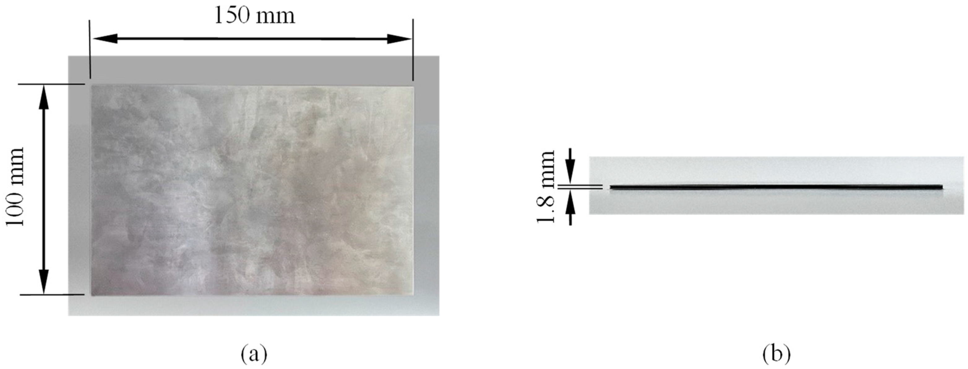
2.1. Specimen
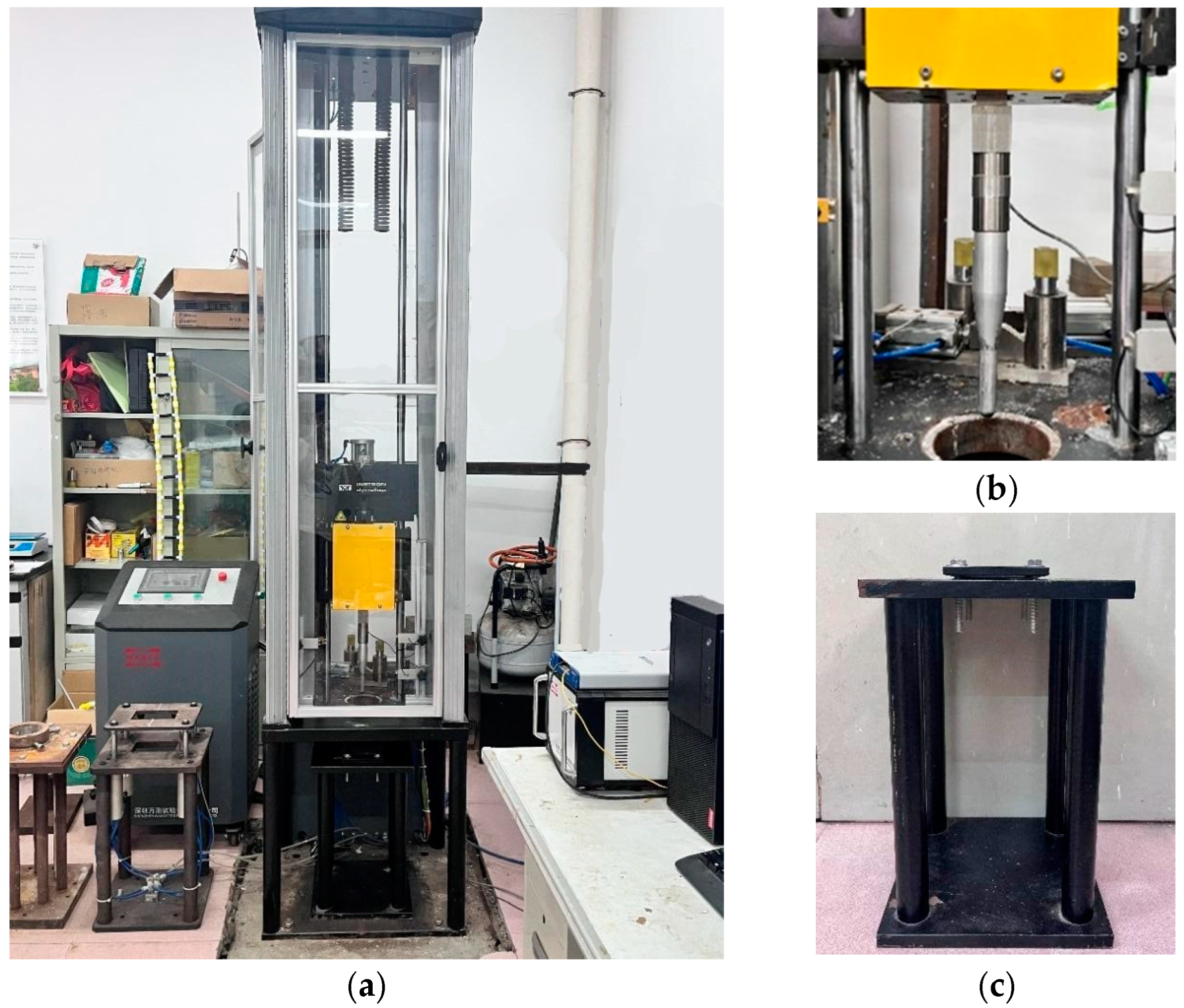
2.2. Experimental Set-Up
3. Numerical Analysis
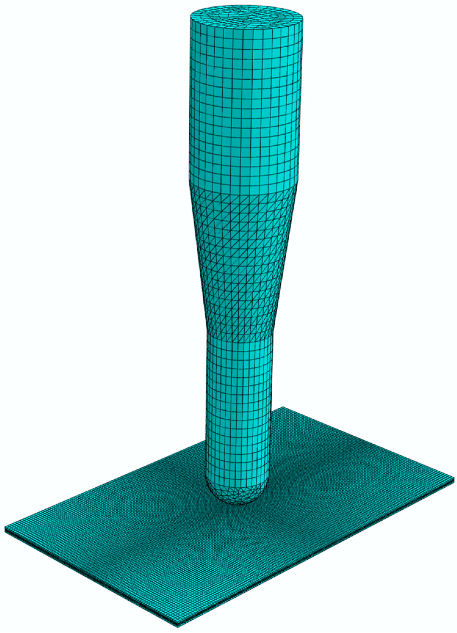
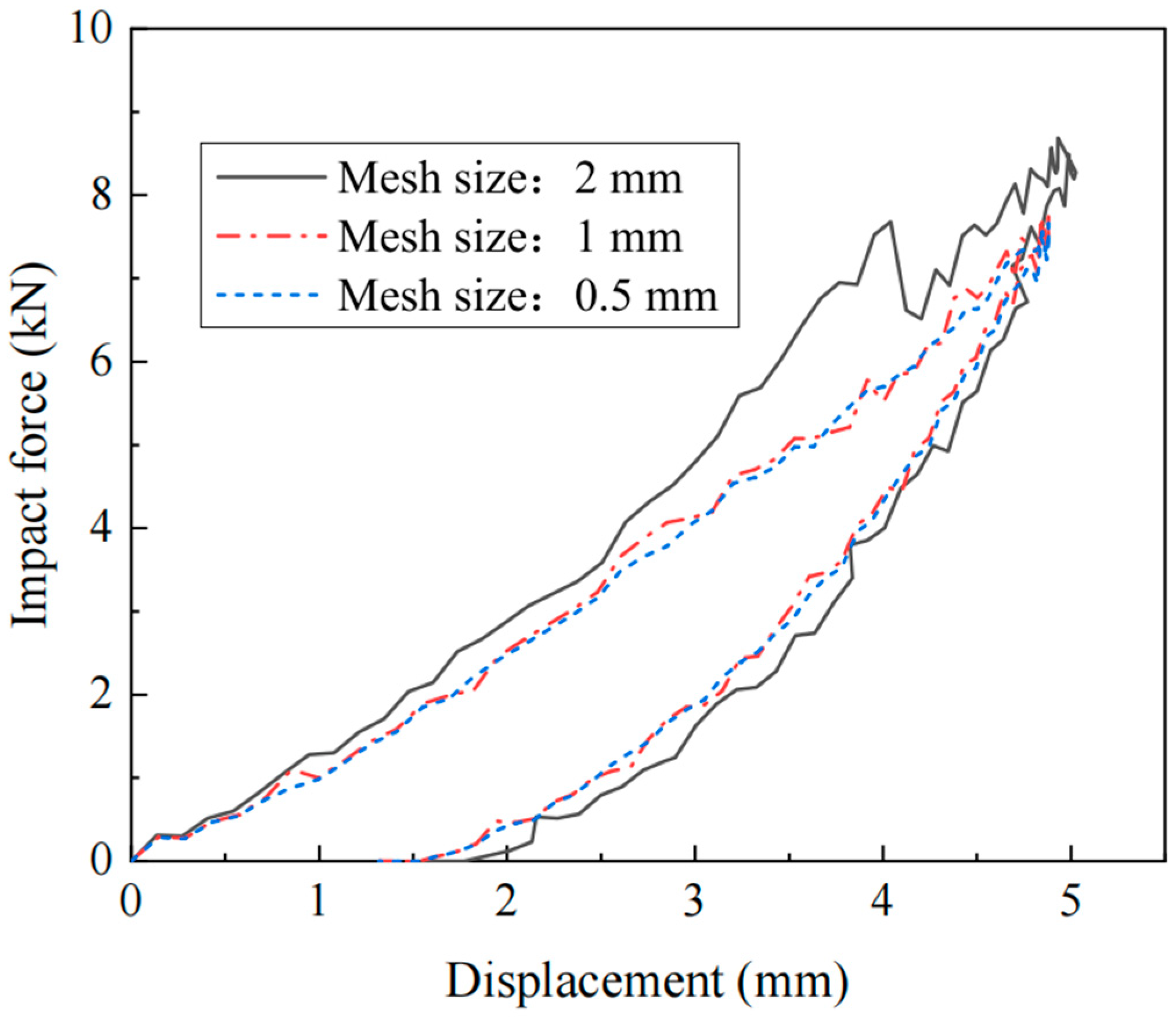
3.1. Numerical Model
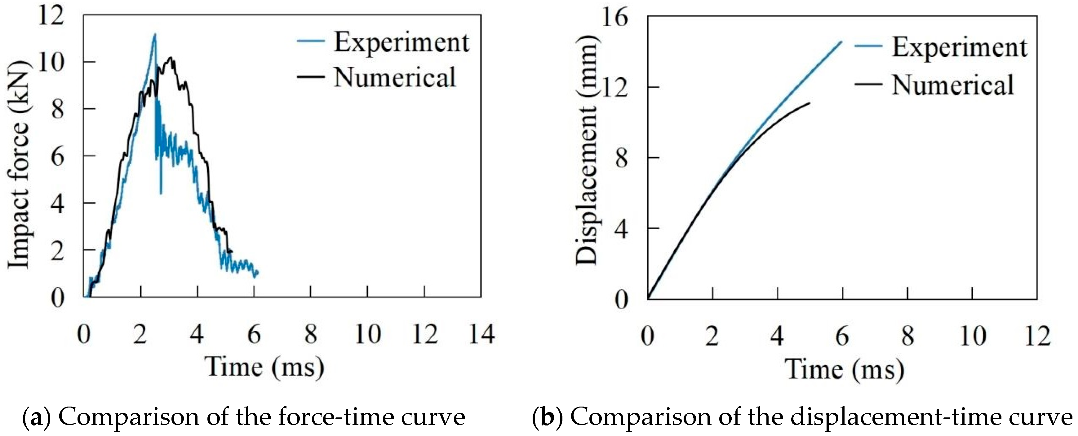
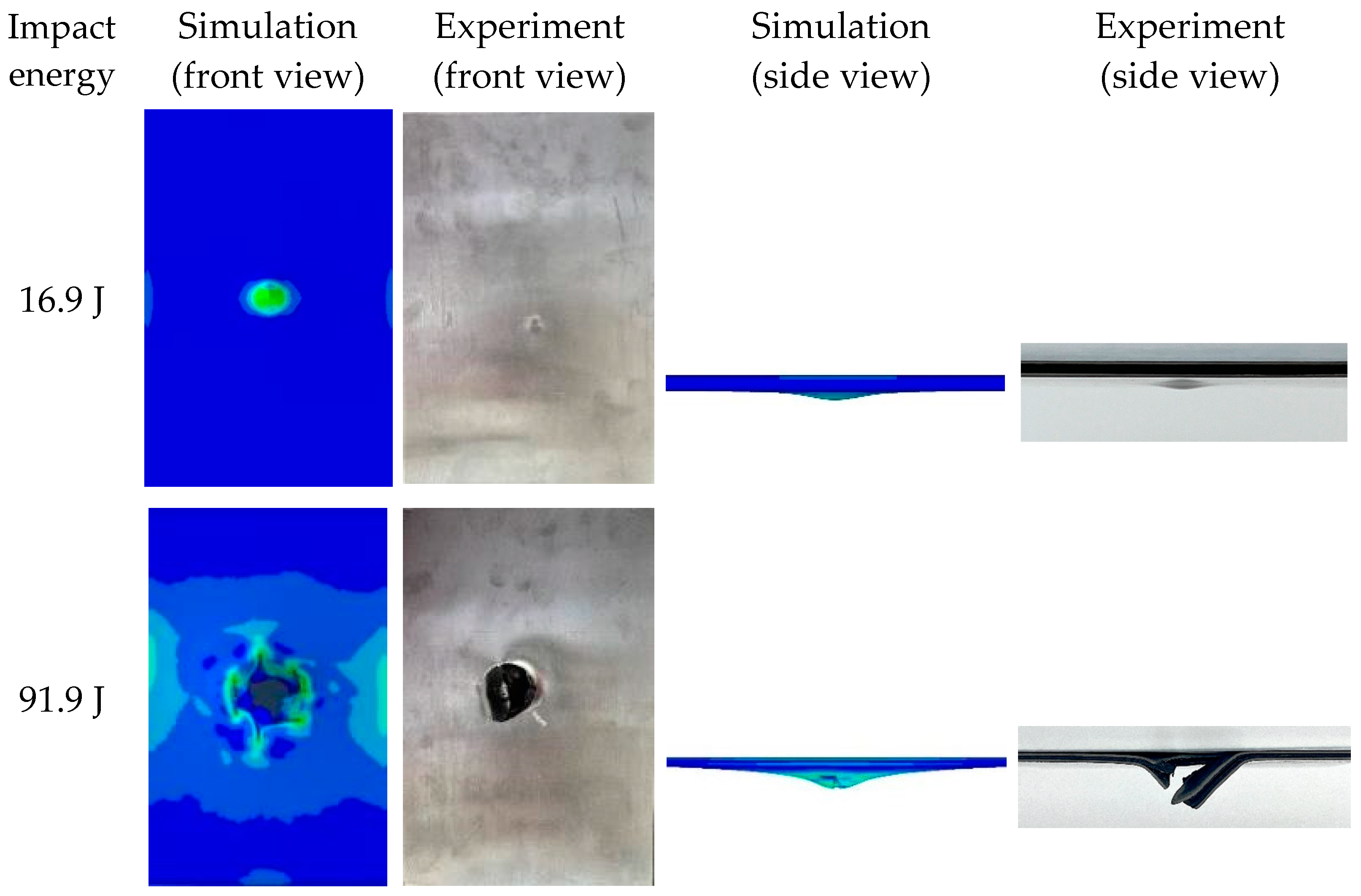
3.2. Numerical Results
4. Results and Discussion
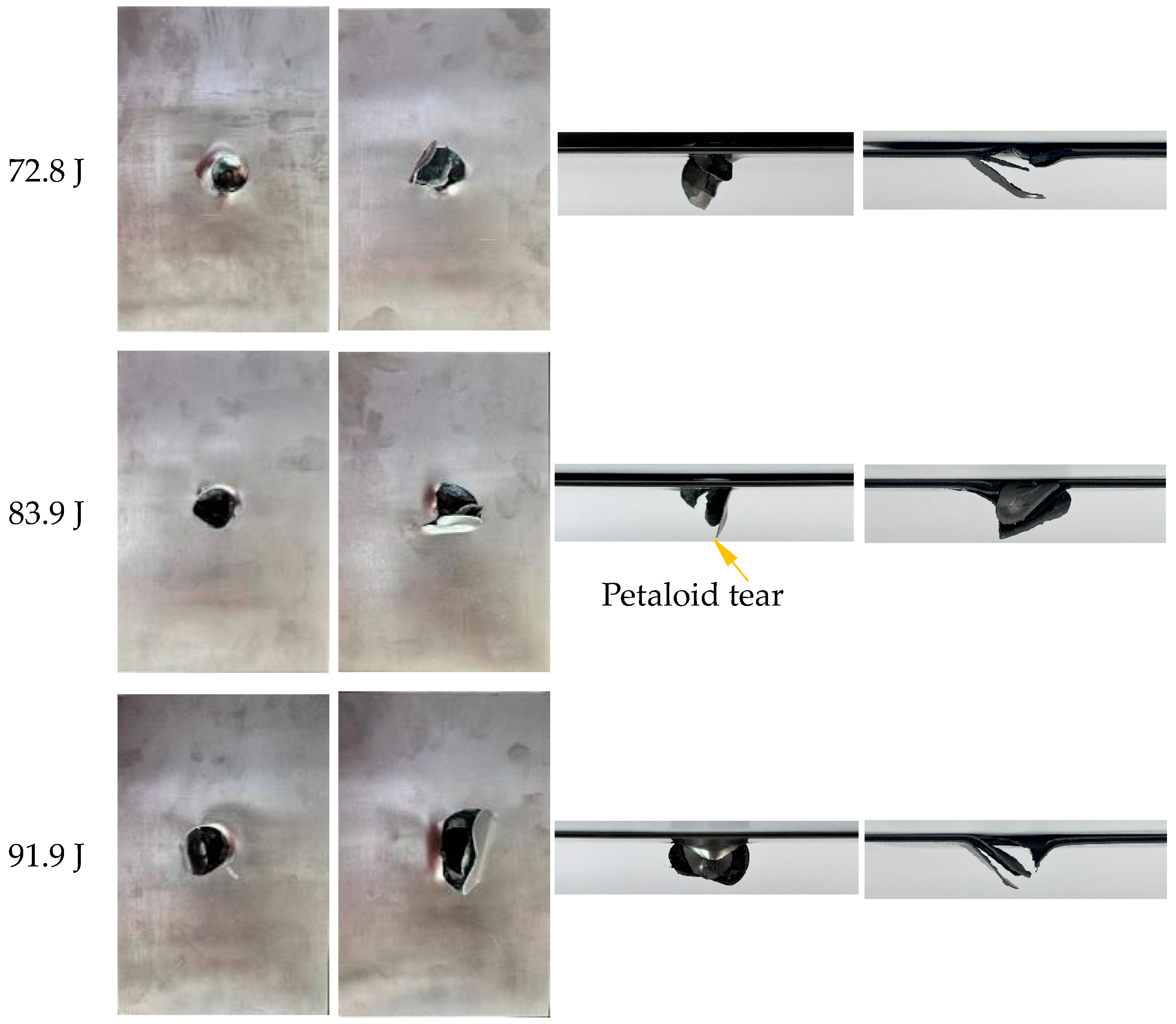
4.1. Damage Mode
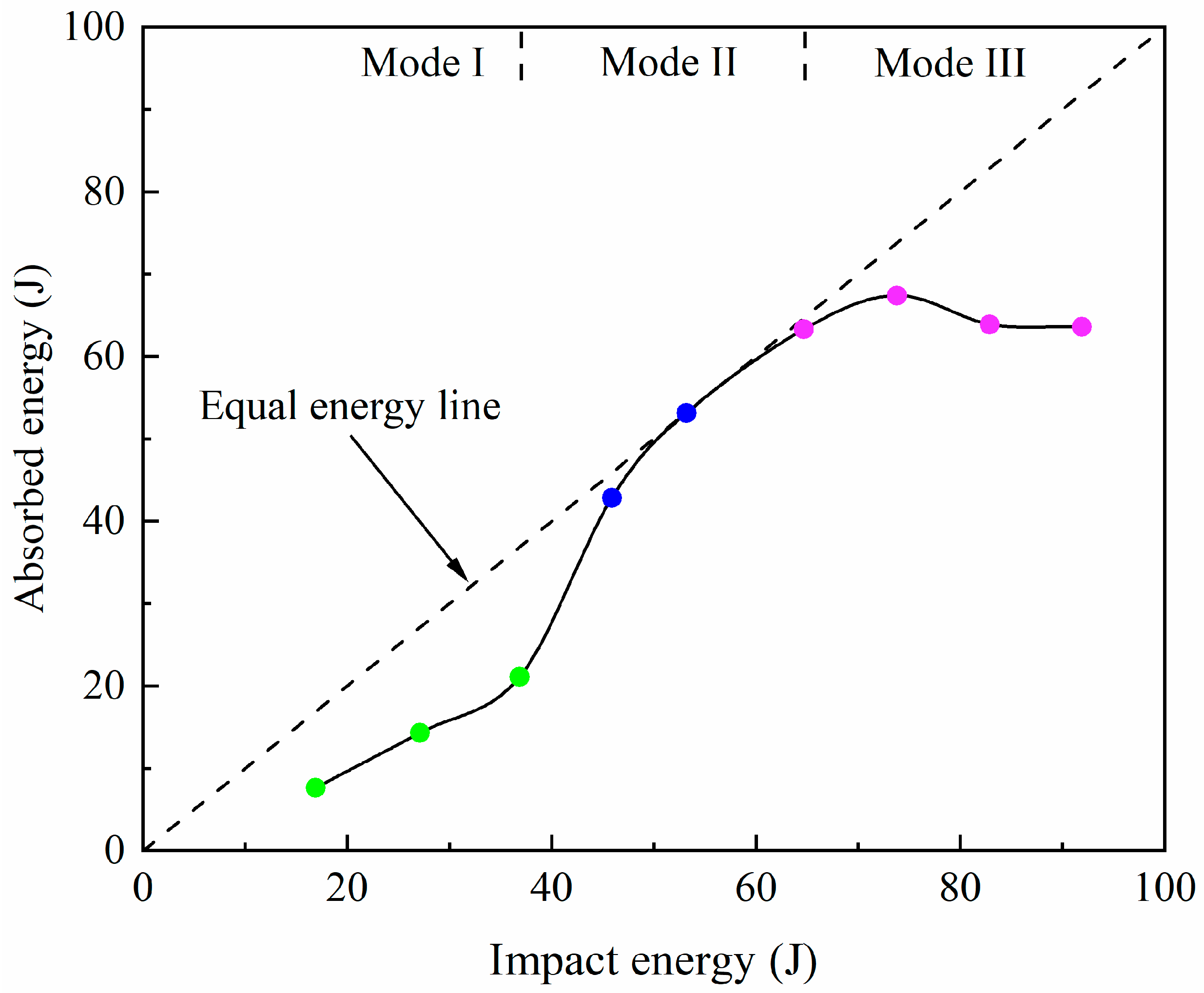
4.2. Energy Absorption
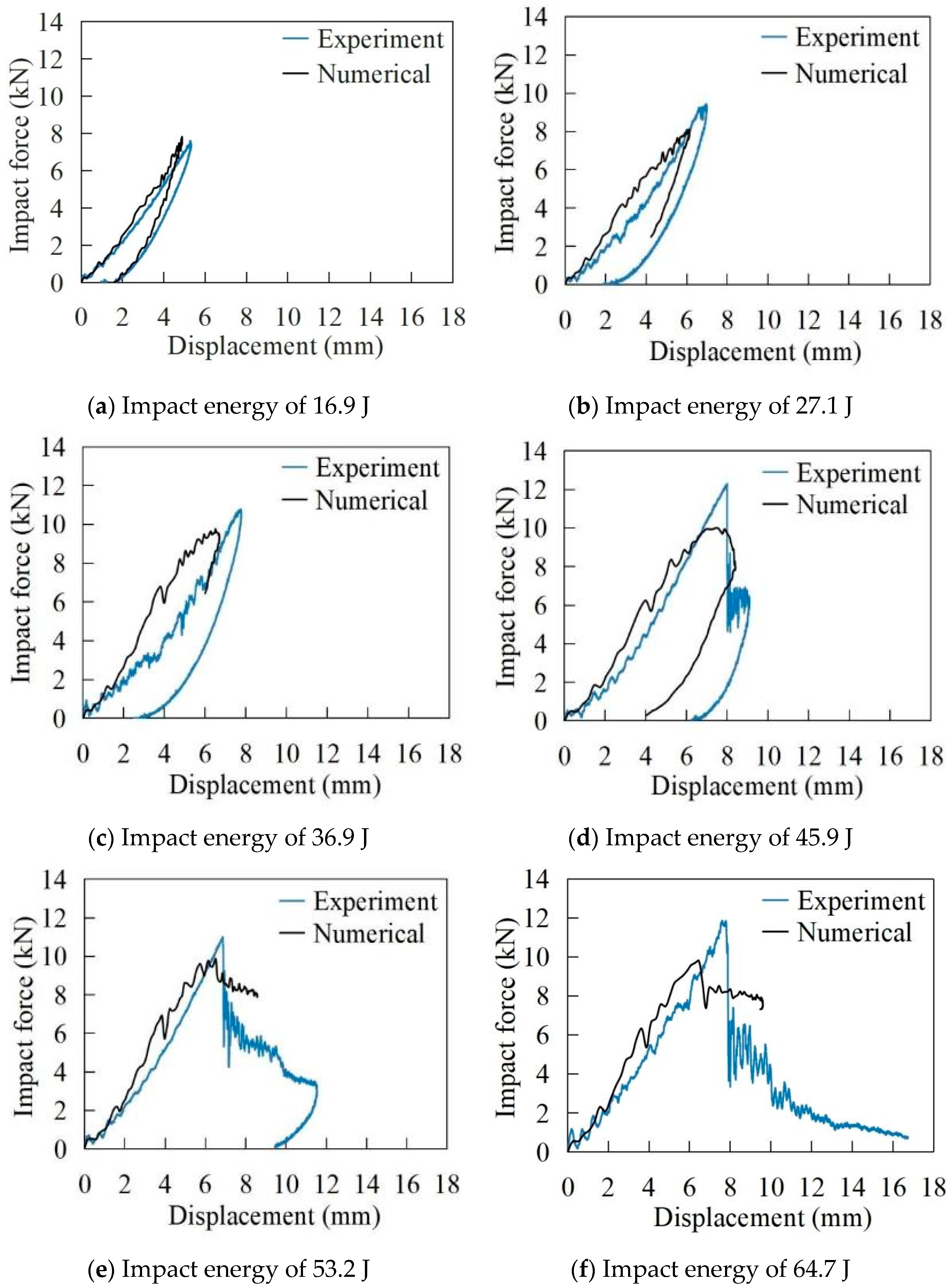
4.3. Impact Force Versus Displacement Curve
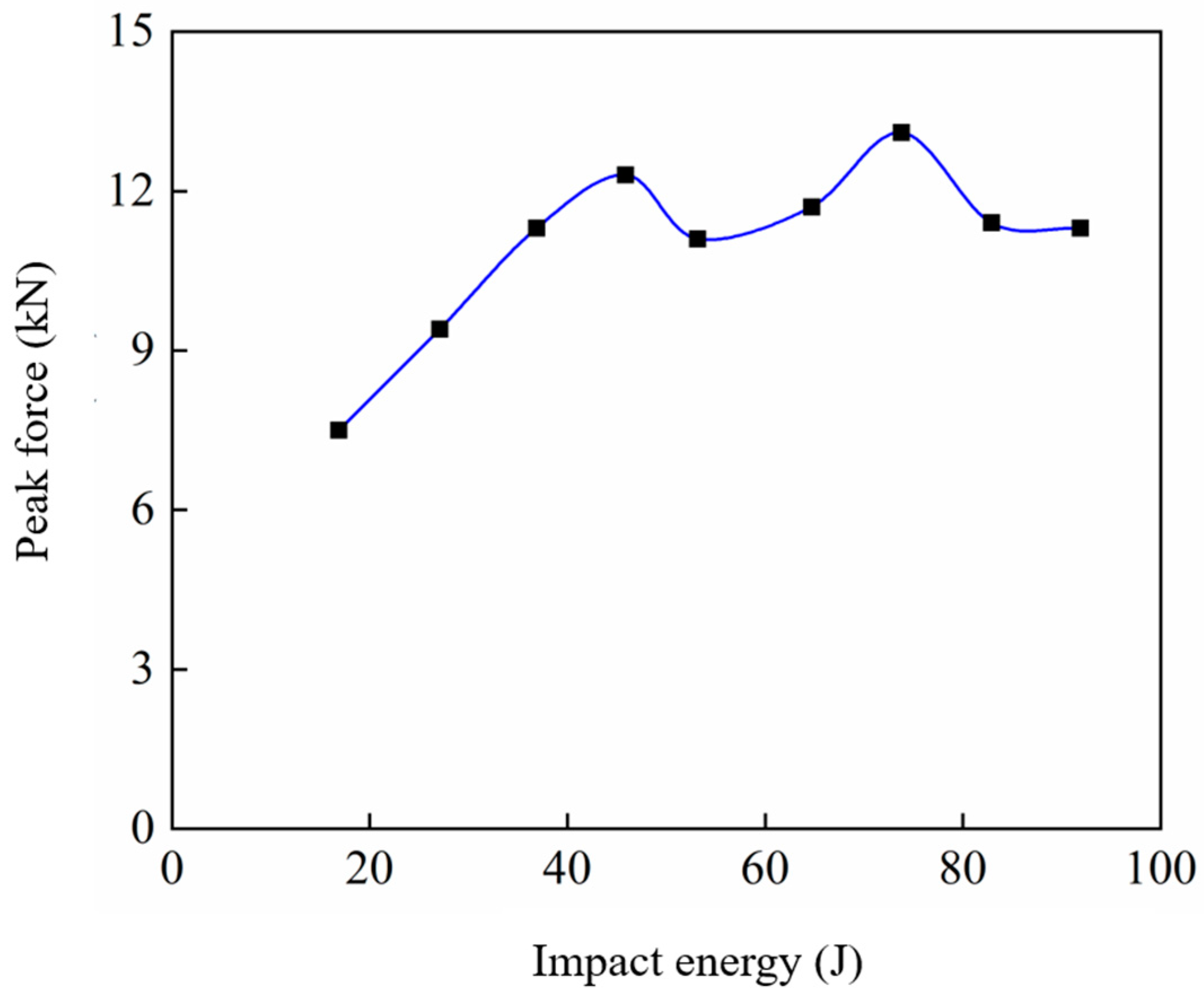
4.4. Peak Force Versus Impact Energy Curve
5. Conclusions
Author Contributions
Funding
Institutional Review Board Statement
Informed Consent Statement
Data Availability Statement
Conflicts of Interest
References
- Ji, C.M.; Hu, J.; Alderliesten, R.; Yang, J.; Zhou, Z.; Sun, Y.; Wang, B. On the post-impact fatigue behavior and theoretical life prediction of CF/PEEK-titanium hybrid laminates using an energy dissipation approach. Compos. Sci. Technol. 2024, 245, 110354. [Google Scholar] [CrossRef]
- Jakubczak, P.; Bienias, J.; Drozdziel, M. The collation of impact behaviour of titanium/carbon, aluminum/carbon and conventional carbon fibres laminates. Thin-Walled Struct. 2020, 155, 106952. [Google Scholar] [CrossRef]
- Jakubczak, P.; Bienias, J.; Drozdziel, M.; Podolak, P.; Harmasz, A. The Effect of Layer Thicknesses in Hybrid Titanium-Carbon Laminates on Low-Velocity Impact Response. Materials 2019, 13, 103. [Google Scholar] [CrossRef] [PubMed]
- Kazemi, M.E.; Shanmugam, L.; Yang, L.; Yang, J. A review on the hybrid titanium composite laminates (HTCLs) with focuses on surface treatments, fabrications, and mechanical properties. Compos. Part A Appl. Sci. Manuf. 2020, 128, 105679. [Google Scholar] [CrossRef]
- Sun, J.; Daliri, A.; Lu, G.; Liu, D.; Xia, F.; Gong, A. Tensile behaviour of titanium-based carbon-fibre/epoxy laminate. Constr. Build. Mater. 2021, 281, 122633. [Google Scholar] [CrossRef]
- Ye, C.; Zhang, P.; Mo, D.; Lu, X.; Yan, F.; Ge, X.; Jiang, P.; Cheng, Y. Dynamic response and microstructure evolution of titanium alloy plates under low-velocity impact. Thin-Walled Struct. 2022, 180, 109888. [Google Scholar] [CrossRef]
- Ye, J.; Gao, Y.; Wu, Y.; Liu, C.; Dong, J.; Wang, H.; Su, B.; Peng, H.-X. Low velocity impact response of fiber metal laminates with nano-patterned metal surfaces. Compos. Sci. Technol. 2022, 228, 109641. [Google Scholar] [CrossRef]
- Li, X.; Zhang, X.; Zhang, H.; Yang, J.; Nia, A.B.; Chai, G.B. Mechanical behaviors of Ti/CFRP/Ti laminates with different surface treatments of titanium sheets. Compos. Struct. 2017, 163, 21–31. [Google Scholar] [CrossRef]
- Sharma, A.P.; Velmurugan, R. Analytical modelling of low-velocity impact response characterization of titanium and glass fibre reinforced polymer hybrid laminate composites. Thin-Walled Struct. 2022, 175, 109236. [Google Scholar] [CrossRef]
- Zheng, Z.Y.; Shen, H.-S.; Wang, H.; Chen, X.; Lu, T. Nonlinear low-velocity impact analysis of sandwich plates with titanium face sheets and porous aluminum core reinforced by GPLs. Alex. Eng. J. 2024, 93, 207–219. [Google Scholar] [CrossRef]
- Sun, J.; Xu, S.; Lu, G.; Ruan, D.; Wang, Q. Mechanical response of fibre metal laminates (FMLs) under low to intermediate strain rate tension. Compos. Struct. 2023, 305, 116493. [Google Scholar] [CrossRef]
- Pan, L.; Hu, J.; Lv, Y.; Ma, W.; Ding, W.; Wang, Y.; Zhang, A.; Wang, F.; Pang, X.; Tao, J. Modification of Ti-6Al-4V plates with Schiff base complex and adhesive performance of Ti-6Al-4V/PEEK. Mater. Des. 2018, 144, 271–280. [Google Scholar] [CrossRef]
- Sun, J.; Daliri, A.; Lu, G.; Ruan, D.; Lv, Y. Tensile failure of fibre-metal-laminates made of titanium and carbon-fibre/epoxy laminates. Mater. Des. 2019, 183, 108139. [Google Scholar] [CrossRef]
- Zhang, W.; Li, R.; Yang, Q.; Fu, Y.; Kong, X. Impact Resistance of a Fiber Metal Laminate Skin Bio-Inspired Composite Sandwich Panel with a Rubber and Foam Dual Core. Materials 2023, 16, 453. [Google Scholar] [CrossRef] [PubMed]
- Ali, A.; Pan, L.; Duan, L.; Zheng, Z.; Sapkota, B. Characterization of seawater hygrothermal conditioning effects on the properties of titanium-based fiber-metal laminates for marine applications. Compos. Struct. 2016, 158, 199–207. [Google Scholar] [CrossRef]
- Hu, Y.B.; Li, H.G.; Cai, L.; Zhu, J.P.; Pan, L.; Xu, J.; Tao, J. Preparation and properties of Fibre–Metal Laminates based on carbon fibre reinforced PMR polyimide. Compos. Part B Eng. 2015, 69, 587–591. [Google Scholar] [CrossRef]
- Wang, L.; Sun, J.; Ding, T.; Liang, Y.; Ho, J.C.M.; Lai, M.H. Manufacture and Behaviour of Innovative 3d Printed Auxetic Composite Panels Subjected to Low-Velocity Impact Load. Structures 2022, 38, 910–933. [Google Scholar] [CrossRef]
- Shanmugam, L.; Kazemi, M.E.; Qiu, C.; Rui, M.; Yang, L.; Yang, J. Influence of UHMWPE fiber and Ti6Al4V metal surface treatments on the low-velocity impact behavior of thermoplastic fiber metal laminates. Adv. Compos. Hybrid Mater. 2020, 3, 508–521. [Google Scholar] [CrossRef]
- Kazemi, M.E.; Bodaghi, M.; Shanmugam, L.; Fotouhi, M.; Yang, L.; Zhang, W.; Yang, J. Developing thermoplastic hybrid titanium composite laminates (HTCLS) at room temperature: Low-velocity impact analyses. Compos. Part A-Appl. Sci. Manuf. 2021, 149, 106552. [Google Scholar] [CrossRef]
- Yang, B.; Chen, Y.; Lee, J.; Fu, K.; Li, Y. In-plane compression response of woven CFRP composite after low-velocity impact: Modelling and experiment. Thin-Walled Struct. 2020, 158, 107186. [Google Scholar] [CrossRef]
- Sharma, A.P.; Velmurugan, R. Damage and energy absorption characteristics of glass fiber reinforced titanium laminates to low-velocity impact. Mech. Adv. Mater. Struct. 2022, 29, 6242–6265. [Google Scholar] [CrossRef]
- Reiner, J.; Torres, J.P.; Veidt, M.; Heitzmann, M. Experimental and numerical analysis of drop-weight low-velocity impact tests on hybrid titanium composite laminates. J. Compos. Mater. 2016, 50, 3605–3617. [Google Scholar] [CrossRef]
- Jakubczak, P.; Bienias, J. The response of hybrid titanium carbon laminates to the low-velocity impact. Eng. Fract. Mech. 2021, 246, 107608. [Google Scholar] [CrossRef]
- Jakubczak, P. The impact behaviour of hybrid titanium glass laminates-Experimental and numerical approach. Int. J. Mech. Sci. 2019, 159, 58–73. [Google Scholar] [CrossRef]
- Yao, L.; Sun, G.; He, W.; Meng, X.; Xie, D. Investigation on impact behavior of FMLs under multiple impacts with the same total energy: Experimental characterization and numerical simulation. Compos. Struct. 2019, 226, 111218. [Google Scholar] [CrossRef]
- Azhdari, S.; Fakhreddini-Najafabadi, S.; Taheri-Behrooz, F. An experimental and numerical investigation on low velocity impact response of GLAREs. Compos. Struct. 2021, 271, 114123. [Google Scholar] [CrossRef]
- Yao, L.; Yu, H.; Wang, C.; He, W. Numerical and experimental investigation on the oblique successive impact behavior and accumulated damage characteristics of fiber metal laminates. Thin-Walled Struct. 2021, 166, 108033. [Google Scholar] [CrossRef]
- Zhang, J.; Qin, Q.; Zhang, J.; Yuan, H.; Du, J.; Li, H. Low-velocity impact on square sandwich plates with fibre-metal laminate face-sheets: Analytical and numerical research. Compos. Struct. 2020, 259, 113461. [Google Scholar] [CrossRef]
- Nassir, N.A.; Birch, R.S.; Cantwell, W.J.; Sierra, D.R.; Edwardson, S.P.; Dearden, G.; Guan, Z. Experimental and numerical characterization of titanium-based fibre metal laminates. Compos. Struct. 2020, 245, 112398. [Google Scholar] [CrossRef]
- Zhu, Q.; Zhang, C.; Curiel-Sosa, J.L.; Quoc Bui, T.; Xu, X. Finite element simulation of damage in fiber metal laminates under high velocity impact by projectiles with different shapes. Compos. Struct. 2019, 214, 73–82. [Google Scholar] [CrossRef]


| Material | Constants | Value | Constants | Value | Constants | Value |
|---|---|---|---|---|---|---|
| Titanium layers | E (GPa) | 113.5 | A (MPa) | 931 | ||
| v | 0.3 | ρ (kg/m3) | 5870 | |||
| Fibre composite layers | Ef1 (GPa) | 130 | Gf12 (GPa) | 3.6 | XT (MPa) | 1760 |
| Ef2 (GPa) | 7.1 | Gf13 (GPa) | 3.6 | XC (MPa) | 1100 | |
| Ef3 (GPa) | 7.1 | Gf23 (GPa) | 3.08 | YT (MPa) | 51 | |
| v12 | 0.32 | S12 (MPa) | 70 | YC (MPa) | 167 | |
| v13 | 0.32 | S13 (MPa) | 70 | S (MPa) | 45 | |
| v23 | 0.52 | S23 (MPa) | 70 | ρ (kg/m3) | 1690 | |
| Cohesive layers | N (MPa) | 60 | GI (MPa) | 0.35 | k (MPa/mm) | 106 |
| S (MPa) | 80 | GII (MPa) | 1.45 | ρ (kg/m3) | 1480 | |
| T (MPa) | 80 | GIII (MPa) | 1.45 |
| Impact Energy (J) | Absorbed Energy (J) |
|---|---|
| 16.9 | 7.6 |
| 27.1 | 14.3 |
| 36.9 | 21.1 |
| 45.9 | 42.8 |
| 53.2 | 53.1 |
| 64.7 | 63.3 |
| 73.8 | 67.4 |
| 82.9 | 63.9 |
| 91.9 | 63.6 |
| Impact Energy (J) | Peak Force (kN) |
|---|---|
| 16.9 | 7.5 |
| 27.1 | 9.4 |
| 36.9 | 11.3 |
| 45.9 | 12.3 |
| 53.2 | 11.1 |
| 64.7 | 11.7 |
| 73.8 | 13.1 |
| 82.9 | 11.4 |
| 91.9 | 11.3 |
Disclaimer/Publisher’s Note: The statements, opinions and data contained in all publications are solely those of the individual author(s) and contributor(s) and not of MDPI and/or the editor(s). MDPI and/or the editor(s) disclaim responsibility for any injury to people or property resulting from any ideas, methods, instructions or products referred to in the content. |
© 2024 by the authors. Licensee MDPI, Basel, Switzerland. This article is an open access article distributed under the terms and conditions of the Creative Commons Attribution (CC BY) license (https://creativecommons.org/licenses/by/4.0/).
Share and Cite
Sun, J.; Chen, W.; Luo, H.; Xie, X.; Zhang, J.; Ding, C. Low-Velocity Impact Behaviour of Titanium-Based Carbon-Fibre/Epoxy Laminate. Materials 2024, 17, 5380. https://doi.org/10.3390/ma17215380
Sun J, Chen W, Luo H, Xie X, Zhang J, Ding C. Low-Velocity Impact Behaviour of Titanium-Based Carbon-Fibre/Epoxy Laminate. Materials. 2024; 17(21):5380. https://doi.org/10.3390/ma17215380
Chicago/Turabian StyleSun, Jing, Weilin Chen, Hongjie Luo, Xingfang Xie, Jingzhou Zhang, and Chao Ding. 2024. "Low-Velocity Impact Behaviour of Titanium-Based Carbon-Fibre/Epoxy Laminate" Materials 17, no. 21: 5380. https://doi.org/10.3390/ma17215380
APA StyleSun, J., Chen, W., Luo, H., Xie, X., Zhang, J., & Ding, C. (2024). Low-Velocity Impact Behaviour of Titanium-Based Carbon-Fibre/Epoxy Laminate. Materials, 17(21), 5380. https://doi.org/10.3390/ma17215380