


Preparation of Electrodes with β-Nickel Hydroxide/CVD-Graphene/3D-Nickel Foam Composite Structures to Enhance the Capacitance Characteristics of Supercapacitors


Abstract
:1. Introduction
2. Experimental Section
2.1. Preparation of Nickel Hydroxide by Hydrothermal Method
2.2. Material Characteristics Analysis
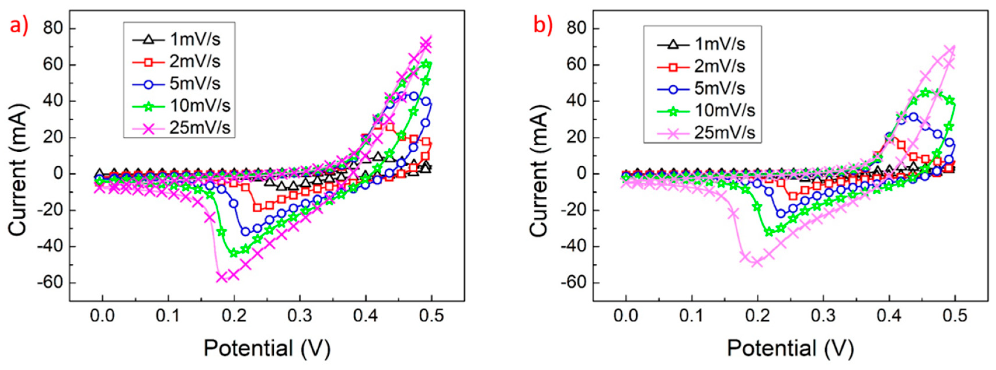
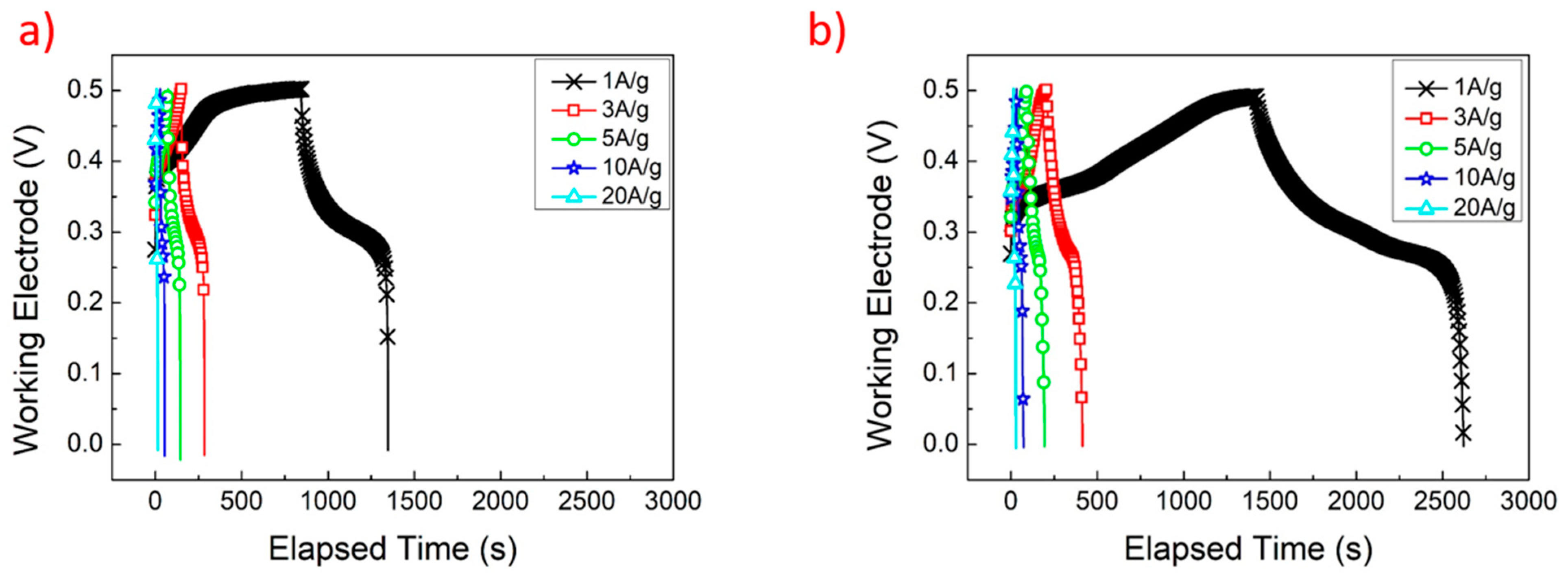
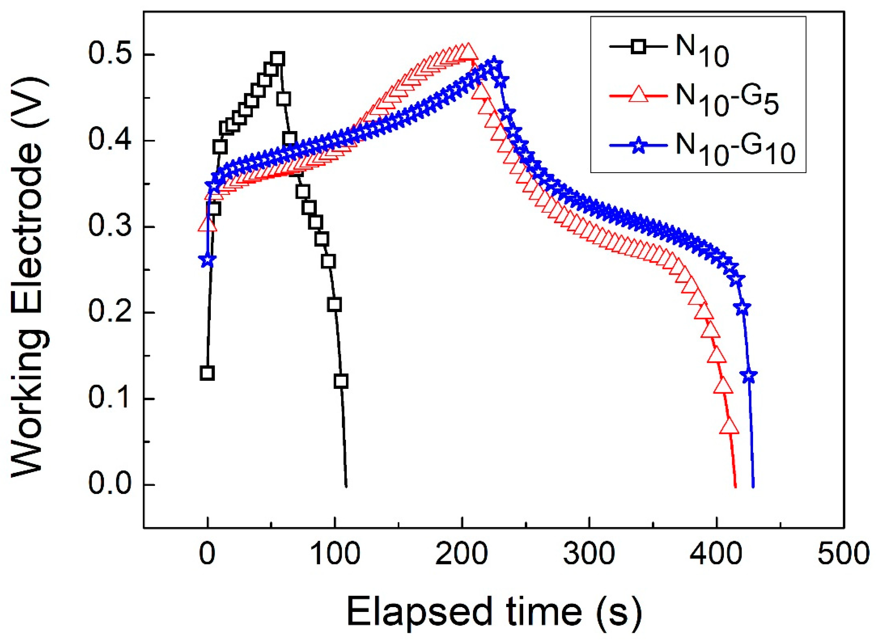
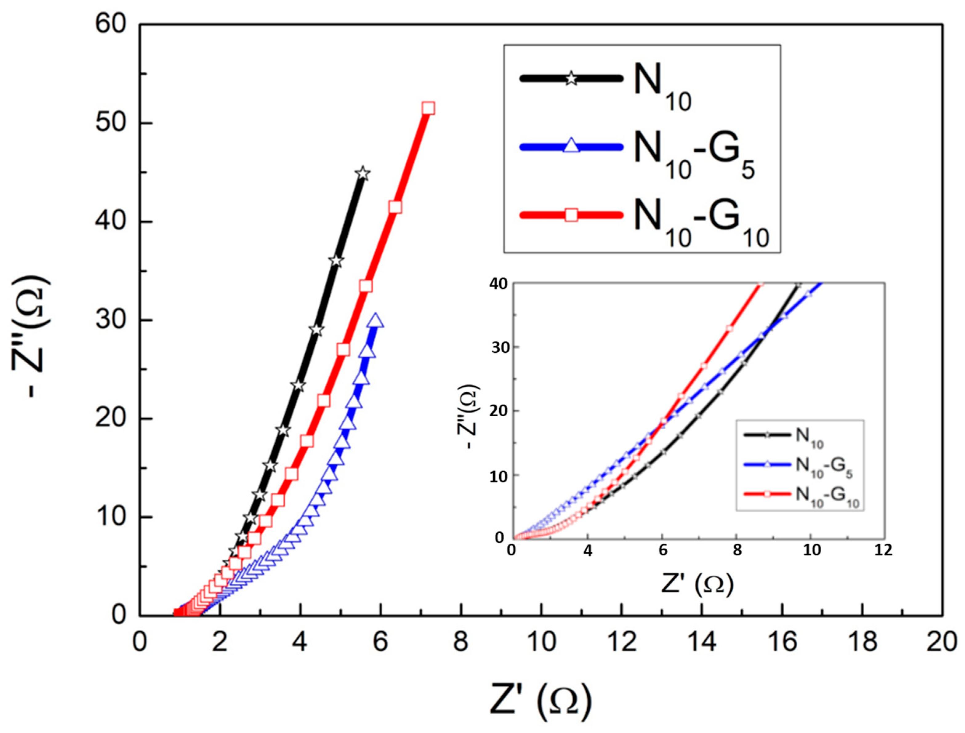
2.3. Electrochemical Characteristics Analysis
3. Result and Discussion
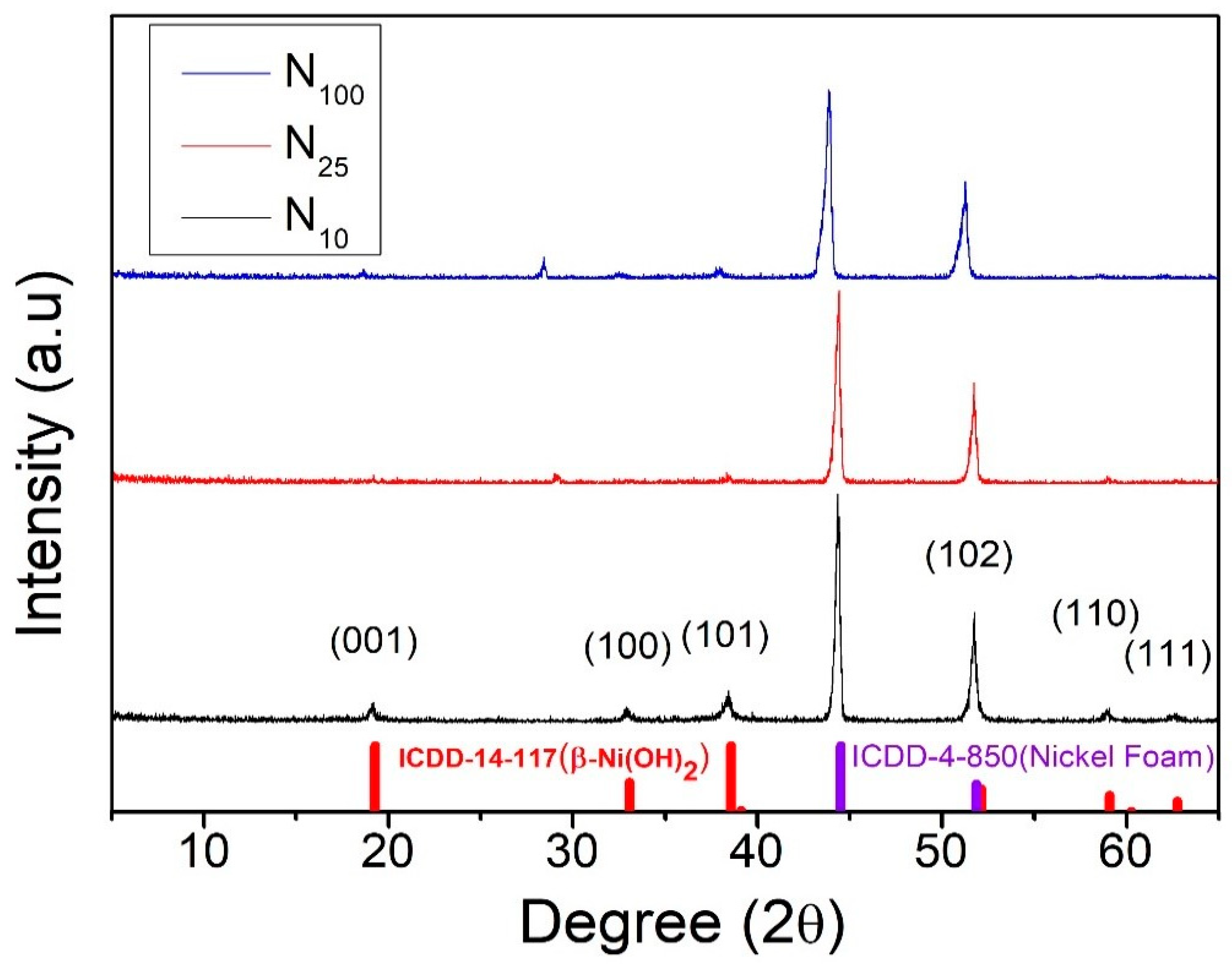
Crystal Structure Analysis of Nickel Hydroxide
4. Conclusions
Author Contributions
Funding
Institutional Review Board Statement
Informed Consent Statement
Data Availability Statement
Conflicts of Interest
References
- Pershaanaa, M.; Bashir, S.; Ramesh, S.; Ramesh, K. Every bite of Supercap: A brief review on construction and enhancement of supercapacitor. J. Energy Storage 2022, 50, 104599. [Google Scholar] [CrossRef]
- Xing, F.; Bi, Z.; Su, F.; Liu, F.; Wu, Z. Unraveling the Design Principles of Battery-Supercapacitor Hybrid Devices: From Fundamental Mechanisms to Microstructure Engineering and Challenging Perspectives. Adv. Energy Mater. 2022, 12, 2200594. [Google Scholar] [CrossRef]
- Robert, J.Y.; Ian, A.K.; Lei, G.; Kostya, S.N. The mechanics of graphene nanocomposites: A review. Compos. Sci. Technol. 2012, 72, 1459–1476. [Google Scholar]
- Sahoo, B.; Pandey, V.; Dogonchi, A.; Thatoi, D.; Nayak, N.; Nayak, M. Synthesis, characterization and electrochemical aspects of graphene based advanced supercapacitor electrodes. Fuel 2023, 345, 128174. [Google Scholar] [CrossRef]
- Wallace, P.R. The band theory of graphite. Phys. Rev. 1947, 71, 622–634. [Google Scholar] [CrossRef]
- Geim, A.K.; Konstantin, S.N. The rise of graphene. Nat. Mater. 2007, 6, 183–191. [Google Scholar] [CrossRef]
- Fang, L.; Ming, P.B.; Li, J. Ab initio calculation of ideal strength and phonon instability of graphene under tension. Phys. Rev. B 2007, 76, 64–120. [Google Scholar]
- Nair, R.R.; Blake, P.; Grigorenko, A.N.; Novoselov, K.S.; Booth, T.J.; Stauber, T.; Peres, N.M.R.; Geim, A.K. Fine Structure Constant Defines Visual Transparency of Graphene. Science 2008, 320, 1308. [Google Scholar] [CrossRef]
- Boehm, H.P.; Setton, R.; Stumpp, E. Nomenclature and terminology of graphite intercalation compounds. Pure Appl. Chem. 1994, 66, 1893–1901. [Google Scholar] [CrossRef]
- Bolotin, K.; Sikes, K.; Jiang, Z.; Klima, M.; Fudenberg, G.; Hone, J.; Kim, P.; Stormer, H. Ultrahigh electron mobility in suspended graphene. Solid State Commun. 2008, 146, 351–355. [Google Scholar] [CrossRef]
- Wu, J.; Lin, H.; Moss, D.J.; Loh, K.P.; Jia, B. Graphene oxide for photonics, electronics and optoelectronics. Nat. Rev. Chem. 2023, 7, 162–183. [Google Scholar] [CrossRef] [PubMed]
- Lu, M.; Zhang, X.; Yin, W.; Wang, Y.; Li, D.; Zhao, Q. Enhanced Performance of Transfer-Free Graphene Transparent Conductive Films on Insulating Substrates by Introducing Array Nanostructure. Eur. J. Inorg. Chem. 2023, 26, e202200779. [Google Scholar] [CrossRef]
- Li, M.; Wang, T.; Liu, X.-L.; Bao, Z.-L.; Qian, P.-F.; Liu, K.; Shi, Y.; Ming, X.; Geng, H.-Z. Highly stable phosphotungstic acid/Au dual doped carbon nanotube transparent conductive films for transparent flexible heaters. Carbon 2023, 207, 219–229. [Google Scholar] [CrossRef]
- Miao, J.; Fan, T. Flexible and stretchable transparent conductive graphene-based electrodes for emerging wearable electronics. Carbon 2023, 202, 495–527. [Google Scholar] [CrossRef]
- Maity, A.; Pu, H.; Sui, X.; Chang, J.; Bottum, K.J.; Jin, B.; Zhou, G.; Wang, Y.; Lu, G.; Chen, J. Scalable graphene sensor array for real-time toxins monitoring in flowing water. Nat. Commun. 2023, 14, 4184. [Google Scholar] [CrossRef] [PubMed]
- Beniwal, A.; Ganguly, P.; Aliyana, A.K.; Khandelwal, G.; Dahiya, R. Screen-printed graphene-carbon ink based disposable humidity sensor with wireless communication. Sens. Actuators B Chem. 2023, 374, 132731. [Google Scholar] [CrossRef]
- Chen, Z.; Yang, Z.; Yu, T.; Wei, Z.; Ji, C.; Zhao, B.; Yu, T.; Yang, W.; Li, Y. Sandwich-structured flexible PDMS@graphene multimodal sensors capable of strain and temperature monitoring with superlative temperature range and sensitivity. Compos. Sci. Technol. 2023, 232, 109881. [Google Scholar] [CrossRef]
- Xu, X.; Du, J.; Cao, Q.; Zhang, D.; Li, C.; Fu, G.; Gao, Y.; Yang, J.; Guan, C.; Huang, W. Digitization of Free-Shapable Graphene Foam with Damage Tolerance. Adv. Funct. Mater. 2023, 33, 2300904. [Google Scholar] [CrossRef]
- Tian, B.; Huang, Z.; Xu, X.; Cao, X.; Wang, H.; Xu, T.; Kong, D.; Zhang, Z.; Xu, J.; Zang, J.; et al. Three-dimensional Ag/carbon nanotube-graphene foam for high performance dendrite free lithium/sodium metal anodes. J. Mater. Sci. Technol. 2023, 132, 50–58. [Google Scholar] [CrossRef]
- Wang, S.; Yang, T.; Wang, C.; Liang, L. The mechanical response and microscopic deformation mechanism of graphene foams tuned by long carbon nanotubes and short crosslinkers. Phys. Chem. Chem. Phys. 2022, 25, 192–202. [Google Scholar] [CrossRef]
- Cheng, Z.; Wang, R.; Wang, Y.; Cao, Y.; Shen, Y.; Huang, Y.; Chen, Y. Recent advances in graphene aerogels as absorption-dominated electromagnetic interference shielding materials. Carbon 2023, 205, 112–137. [Google Scholar] [CrossRef]
- Yang, G.; Zhang, X.; Wang, R.; Liu, X.; Zhang, J.; Zong, L.; Yang, H. Ultra-stretchable graphene aerogels at ultralow temperatures. Mater. Horiz. 2023, 10, 1865–1874. [Google Scholar] [CrossRef] [PubMed]
- Zhou, A.; Yu, T.; Liang, X.; Yin, S. H2O2-free strategy derived from Hummers method for preparing graphene oxide with high oxidation degree. FlatChem 2023, 38, 100487. [Google Scholar] [CrossRef]
- Tseng, L.-H.; Li, W.-C.; Wen, T.-C. The effectiveness of graphene oxide added in activated carbon for superior supercapacitor performance. J. Taiwan Inst. Chem. Eng. 2023, 143, 104684. [Google Scholar] [CrossRef]
- Mahvi, A.H.; Balarak, D.; Bazrafshan, E. Remarkable reusability of magnetic Fe3O4-graphene oxide composite: A highly effective adsorbent for Cr(VI) ions. Int. J. Environ. Anal. Chem. 2021, 103, 3501–3521. [Google Scholar] [CrossRef]
- Jeong, S.; Yang, S.; Kim, B.G.; Lee, H.J.; Bae, J.J.; Kim, J.H.; Lee, W.; Hwang, J.Y.; Choi, S.; Jeong, H.J.; et al. Highly conductive quasi-defect-free reduced graphene oxide for qualitative scalable production. Carbon 2023, 203, 221–229. [Google Scholar] [CrossRef]
- Zhang, H.; Xie, Y.; Yang, S.; Gao, X.; Bai, H.; Yao, F.; Yue, H. NiCo2S4 nanocone arrays on three-dimensional graphene with small hole diameters for asymmetric supercapacitor. J. Alloys Compd. 2023, 968, 171694. [Google Scholar] [CrossRef]
- Ma, Q.; Liu, M.; Cui, F.; Zhang, J.; Cui, T. Fabrication of 3D graphene microstructures with uniform metal oxide nanoparticles via molecular self-assembly strategy and their supercapacitor performance. Carbon 2023, 204, 336–345. [Google Scholar] [CrossRef]
- Smaisim, G.F.; Abed, A.M.; Al-Madhhachi, H.; Hadrawi, S.K.; Al-Khateeb, H.M.M.; Kianfar, E. Graphene-Based Important Carbon Structures and Nanomaterials for Energy Storage Applications as Chemical Capacitors and Supercapacitor Electrodes: A Review. BioNanoScience 2023, 13, 219–248. [Google Scholar] [CrossRef]
- Braga, F.; Casano, G.; Daniels, L.M.; Caffio, M.; Hardwick, L.J. Electrodeposition of manganese dioxide coatings onto graphene foam substrates for electrochemical capacitors. Electrochim. Acta 2023, 455, 142433. [Google Scholar] [CrossRef]
- Zhang, C.; Lee, B.-J.; Li, H.; Samdani, J.; Kang, T.-H.; Yu, J.-S. Catalytic mechanism of graphene-nickel interface dipole layer for binder free electrochemical sensor applications. Commun. Chem. 2018, 1, 94. [Google Scholar] [CrossRef]
- Kozlov, S.M.; Viñes, F.; Görling, A. Bonding Mechanisms of Graphene on Metal Surfaces. J. Phys. Chem. C 2012, 116, 7360–7366. [Google Scholar] [CrossRef]
- Ho, H.-Y.; Chu, H.-I.; Huang, Y.-J.; Tsai, D.-S.; Lee, C.-P. Polypyrrole-coated copper@graphene core-shell nanoparticles for supercapacitor application. Nanotechnology 2023, 34, 125401. [Google Scholar] [CrossRef] [PubMed]
- Deyab, M.; Awadallah, A.E.; Ahmed, H.A.; Mohsen, Q. Progress study on nickel ferrite alloy-graphene nanosheets nanocomposites as supercapacitor electrodes. J. Energy Storage 2022, 46, 103926. [Google Scholar] [CrossRef]
- Ren, H.; Zhang, L.; Zhang, J.; Miao, T.; Yuan, R.; Chen, W.; Wang, Z.; Yang, J.; Zhao, B. Na+ pre-intercalated Na0.11MnO2 on three-dimensional graphene as cathode for aqueous zinc ion hybrid supercapacitor with high energy density. Carbon 2022, 198, 46–56. [Google Scholar] [CrossRef]
- Lu, Y.-M.; Hong, S.-H. Controlling the Cooling Rate of Hydrothermal Synthesis to Enhance the Supercapacitive Properties of β-Nickel Hydroxide Electrode Materials. Materials 2023, 16, 5576. [Google Scholar] [CrossRef] [PubMed]
- Lee, K.K.; Deng, S.; Fan, H.M.; Mhaisalkar, S.; Tan, H.R.; Tok, E.S.; Loh, K.P.; Chin, W.S.; Sow, C.H. α-Fe2O3 nanotubes-reduced graphene oxide composites as synergistic electrochemical capacitor materials. Nanoscale 2012, 4, 2958–2961. [Google Scholar] [CrossRef]
- Kim, B.K.; Chabot, V.; Yu, A. Carbon nanomaterials supported Ni (OH)2/NiO hybrid flower structure for supercapacitor Electrochim. Acta 2013, 109, 370–380. [Google Scholar]
- Sfyris, D.; Sfyris, G.I.; Galiotis, C. Stress intrepretation of graphene E-2g and A-1g vibrational modes: Theoretical analysis. arXiv 2017, arXiv:1706.04465. [Google Scholar]
- Eftekhari, A. Energy efficiency: A critically important but neglected factor in battery research. Sustain. Energy Fuels 2017, 1, 2053–2060. [Google Scholar] [CrossRef]
- Asghar, A.; Rashid, M.; Javed, Y.; Hussain, S.; Shad, N.A.; Hamza, M.; Chen, Z. Facile hydrothermal synthesis of MoS2 nano-worms-based aggregate as electrode material for high energy density asymmetric supercapacitor. Electrochim. Acta 2023, 465, 143011. [Google Scholar] [CrossRef]
- Balasubramani, V.; Girija, R.; Muthuvinayagam, M.; Maiz, F.; Shkir, M.; Reddy, V.R.M.; Kim, W.K. MgCo2O4 nanosheets//NF as a potential electrode with enhanced cycling performance for symmetric supercapacitor. Mater. Sci. Eng. B 2023, 297, 116806. [Google Scholar] [CrossRef]
- Hamedani, H.; Ghasemi, A.K.; Kafshgari, M.S.; Zolfaghari, Y.; Kafshgari, L.A. Electrochemical performance of 3D porous PANI/Gr/MIL-100(Fe) nanocomposite as a novel smart supercapacitor electrode material. Synth. Met. 2023, 298, 117428. [Google Scholar] [CrossRef]
- Manikandan, M.; Kulurumotlakatla, D.K.; Manikandan, E.; Karthigeyan, K.; Al-Kahtani, A.A. Hydrothermal synthesis of rGO/ZnCoS composite for high performance asymmetric supercapacitor and HER applications. J. Energy Storage 2023, 72, 108769. [Google Scholar] [CrossRef]
- Ling, L.; Zhang, C.; Lai, D.; Su, M.; Gao, F.; Lu, Q. Simultaneous phosphorization and sulfuration to Synergistically promote the supercapacitor performance of heterogeneous (CoxNi1-x)2P/CoxNi1-xS hydrangea-like microspheres. J. Power Sources 2023, 581, 233487. [Google Scholar] [CrossRef]
- Zhao, S.; Wu, F.; Yang, L.; Gao, L.; Burke, A.F. A measurement method for determination of dc internal resistance of batteries and supercapacitors. Electrochem. Commun. 2010, 12, 242–245. [Google Scholar] [CrossRef]
- Negroiu, R.; Svasta, P.; Pirvu, C.; Vasile, A.; Marghescu, C. Electrochemical impedance spectroscopy for different types of supercapacitors. In Proceedings of the 2017 40th International Spring Seminar on Electronics Technology (ISSE), Sofia, Bulgaria, 10–14 May 2017; pp. 1–4. [Google Scholar] [CrossRef]


| Electrode Structure | Charge and Discharge Current (A/g) | Capacitance without Graphene (F/g) | Capacitance with Graphene (F/g) | Reference in This Work |
|---|---|---|---|---|
| PPy/Multilayer Graphene/Cu NPs | 1 | 214 | 845 | [33] |
| NiFe/Graphene | 1 | 264 | 845 | [34] |
| Na0.11MnO2/3DG | 0.2 | 686 | 1240 | [35] |
| β-Ni(OH)2/graphene | 1 | 538.7 | 2015.2 | This work |
| Cooling Rate (Sample Structure) | 10 °C/hour, (β-Ni(OH)2/NF) | 10 °C/hour, G5 Middle Layer (β-Ni(OH)2/G5/NF) | 10 °C/hour, G10 Middle Layer (β-Ni(OH)2/G10/NF) |
|---|---|---|---|
| sample name | N10 | N10-G5 | N10-G10 |
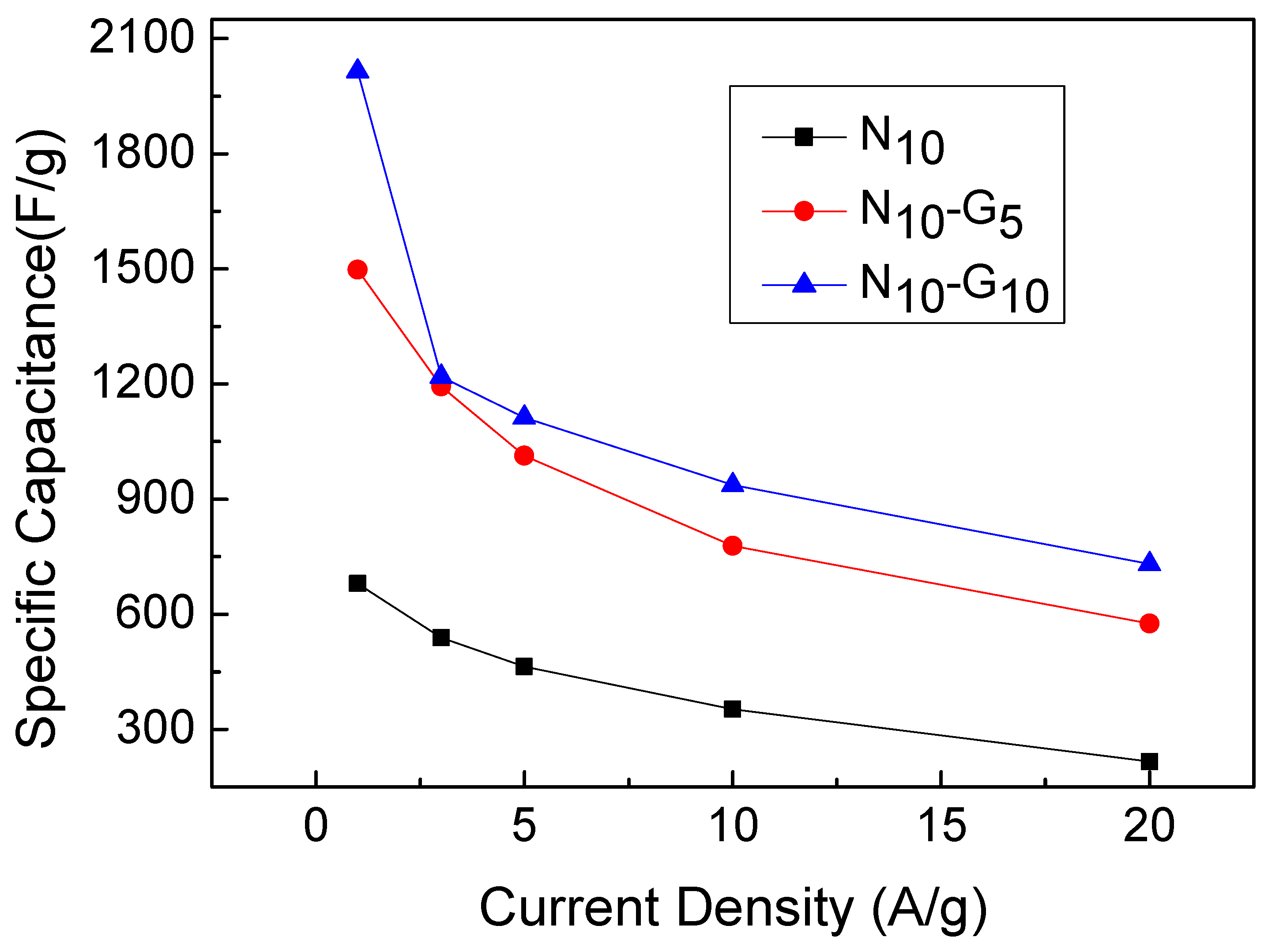
| Current Density (A/g) | N10 | N10-G5 | N10-G10 |
| 1 | 680 | 1498 | 2015 |
| 3 | 539 | 1193 | 1219 |
| 5 | 464 | 1013 | 1112 |
| 10 | 353 | 778 | 937 |
| 20 | 216 | 576 | 731 |
| Sample Number | N10 | N10-G5 | N10-G10 |
|---|---|---|---|
| Energy efficiency | 90.4% | 65% | 78% |
| Materials | Specific Capacitance (F/g) | Test Parameter (CV/GCD) | Ref. in This Work |
|---|---|---|---|
| MoS2 nanoworms | 1866 | 5 mV/s (CV) | [41] |
| MgCo2O4 nanosheets | 1460 | 2 mA/cm2 (GCD) | [42] |
| PANI/Graphene/MIL-100(Fe) | 638 | 1 A/g | [43] |
| rGO/ZnCoS | 891 | 1 A/g | [44] |
| (CoxNi1-x)2P/CoxNi1-xS | 1561 | 1 A/g | [45] |
| Ni(OH)2/Graphene | 2015 | 1 A/g | This work |
Disclaimer/Publisher’s Note: The statements, opinions and data contained in all publications are solely those of the individual author(s) and contributor(s) and not of MDPI and/or the editor(s). MDPI and/or the editor(s) disclaim responsibility for any injury to people or property resulting from any ideas, methods, instructions or products referred to in the content. |
© 2023 by the authors. Licensee MDPI, Basel, Switzerland. This article is an open access article distributed under the terms and conditions of the Creative Commons Attribution (CC BY) license (https://creativecommons.org/licenses/by/4.0/).
Share and Cite
Lu, Y.-M.; Hong, S.-H. Preparation of Electrodes with β-Nickel Hydroxide/CVD-Graphene/3D-Nickel Foam Composite Structures to Enhance the Capacitance Characteristics of Supercapacitors. Materials 2024, 17, 23. https://doi.org/10.3390/ma17010023
Lu Y-M, Hong S-H. Preparation of Electrodes with β-Nickel Hydroxide/CVD-Graphene/3D-Nickel Foam Composite Structures to Enhance the Capacitance Characteristics of Supercapacitors. Materials. 2024; 17(1):23. https://doi.org/10.3390/ma17010023
Chicago/Turabian StyleLu, Yang-Ming, and Sheng-Huai Hong. 2024. "Preparation of Electrodes with β-Nickel Hydroxide/CVD-Graphene/3D-Nickel Foam Composite Structures to Enhance the Capacitance Characteristics of Supercapacitors" Materials 17, no. 1: 23. https://doi.org/10.3390/ma17010023
APA StyleLu, Y.-M., & Hong, S.-H. (2024). Preparation of Electrodes with β-Nickel Hydroxide/CVD-Graphene/3D-Nickel Foam Composite Structures to Enhance the Capacitance Characteristics of Supercapacitors. Materials, 17(1), 23. https://doi.org/10.3390/ma17010023