Article

A Micromechanical Study of Interactions of Cyanate Ester Monomer with Graphene or Boron Nitride Monolayer

1
Department of Physics, Michigan Technological University, Houghton, MI 49931, USA
2
MALTA-Consolider Team and Departamento de Química Física y Analítica, Universidad de Oviedo, 33006 Oviedo, Spain
3
Department of Mechanical Engineering and Engineering Mechanics, Michigan Technological University, Houghton, MI 49931, USA
*
Authors to whom correspondence should be addressed.
Materials 2024, 17(1), 108; https://doi.org/10.3390/ma17010108
Submission received: 5 December 2023 / Revised: 17 December 2023 / Accepted: 22 December 2023 / Published: 25 December 2023
(This article belongs to the Section Materials Simulation and Design)

Abstract

:
Polymer composites, hailed for their ultra-strength and lightweight attributes, stand out as promising materials for the upcoming era of space vehicles. The selection of the polymer matrix plays a pivotal role in material design, given its significant impact on bulk-level properties through the reinforcement/polymer interface. To aid in the systematic design of such composite systems, molecular-level calculations are employed to establish the relationship between interfacial characteristics and mechanical response, specifically stiffness. This study focuses on the interaction of fluorinated and non-fluorinated cyanate ester monomers with graphene or a BN monolayer, representing non-polymerized ester composites. Utilizing micromechanics and the density functional theory method to analyze interaction energy, charge density, and stiffness, our findings reveal that the fluorinated cyanate-ester monomer demonstrates lower interaction energy, reduced pull-apart force, and a higher separation point compared to the non-fluorinated counterpart. This behavior is attributed to the steric hindrance caused by fluorine atoms. Furthermore, the BN monolayer exhibits enhanced transverse stiffness due to increased interfacial strength, stemming from the polar nature of B–N bonds on the surface, as opposed to the C-C bonds of graphene. These molecular-level results are intended to inform the design of next-generation composites incorporating cyanate esters, specifically for structural applications.

1. Introduction

Deep space exploration into the solar system requires technology advancements for space vehicles that can sustain a voyage with minimal mass and volume. Polymer matrix composites, especially those reinforced with carbon fibers, have gained popularity in aerospace applications in recent years due to their high stiffness-to-weight ratio, which results in significant weight and fuel savings on commercial and military aircraft [1,2,3]. It has been recognized that existing carbon fiber-based composite materials are insufficient for a manned mission to Mars [4]. However, one expects nanomaterials, including graphene and carbon nanotubes (CNTs), can exceed the mechanical properties of carbon fibers used for structural reinforcements in composites [5]. Essentially, composites are engineered materials that consist of at least two materials that are significantly different in terms of their chemical or physical properties.
Because of their excellent mechanical properties, CNTs are a good reinforcement for high-performance polymer matrix composites. With a Young’s modulus of approximately 1 TPa, carbon nanotubes serve as effective reinforcements for materials with exceptional stiffness and strength. However, CNTs dispersed in a polymer matrix have lower stiffness and strength than isolated ones [6]. The challenge related to the dispersion of CNTs arises from inadequate noncovalent bonding between neighboring CNTs, resulting in the deformation-induced movement of CNTs [7]. On the other hand, CNTs with a large diameter (~10 nm), also called flattened CNTs (flCNTs), observed in nanocomposites formed with highly aligned thin CNT films and bismaleimide (BMI) (a type of resin) have been found to have remarkably high tensile strength compared to that of small-diameter CNTs because of their large contact area, and hence a higher degree of noncovalent type of bonding among themselves [6]. For example, the mechanically stretched sheets of flCNTs combined with BMI resin were 78% and 283% greater in Young’s modulus and tensile strength, respectively, than sheets of randomly oriented CNT with BMI resin. These flCNT bundles can thus serve as highly effective reinforcing materials [6].
FlCNTs are stacked layers of two-dimensional graphene [8] in which van der Waals forces dominate the interlayer interactions. This weak attractive interaction compensates for the energy loss from forming reactive edges and provides stability to flCNTs [9]. In the present study, we show that graphene representing the graphitic structure of flCNTs can provide excellent interfacial strength in forming polymer composites.
The question now becomes “Which polymer matrix is most compatible with graphene?” The efficacy of load transfer between composite constituents is determined by the binding strength (or interaction strength at the interface). In this paper, we aim to gain a comprehensive understanding of the fundamental interactions occurring at the monomer–monolayer level during the reinforcement process. By narrowing our focus to the monomer stage, we can elucidate the molecular-level mechanisms, surface energetics, and bonding characteristics that play a major role in the overall performance of the cured polymer composites.
Previously, Sachdeva et al. [10] used density functional theory (DFT) to investigate the interaction properties and mechanical characteristics of two different (epoxy and BMI) monomers interacting with graphene. They demonstrated that various functional groups (e.g., R-O-R in epoxy resin) significantly affect the interfacial interaction energy, pull-apart force, and separation point. Although the reported results are essential in determining the behavior of monomer/graphene interfaces, it is unclear how it interacts with other monomer systems that could be employed in graphene-based polymer composites.
In general, it is expected that functional groups containing nitrogen will be most compatible with graphene-based composites due to the interaction between amide/amine and the orbitals of graphitic structures (i.e., NH2–π interaction) [11]. Accordingly, aromatic cyanate esters, Primaset PT-30 and AroCy F-10, consisting of nitrogen-containing functional groups, can be candidate matrices for such composites. These ester resins have evolved as a distinct and new category of thermosetting resins with excellent performance employed in structural applications as matrices [12]. The cyanate ester resins have some basic features, such as low moisture absorption, good electrical qualities, easy processability, good flammability characteristics, high service temperature, and toughness, which makes them ideal composite matrices and a competitor for epoxy and bismaleimides resins in structural applications [13,14,15,16].
Cyanate esters are characterized by a phenol backbone with cyanate (-OCN) groups attached at each end of the monomer. AroCy F-10 is a fluorinated cyanate ester (Figure 1a) with a tensile strength of 75 MPa, an elastic modulus of 3.11 GPa, and a maximum strain of 2.8%, and fracture toughness of 140 Jm−2 [17]. Primaset PT is a non-fluorinated cyanate ester (Figure 1b) with a tensile strength of 77 MPa, a tensile modulus of 4.0 GPa, a strain-to-break of 2.0%, and a flexural strength of 112 MPa [18]. In this work, we consider the complexes consisting of an ester monomer and graphene (or BN) monolayer to provide an atomistic description of the interface via interaction energy, the density of states, and Bader’s charge [19] and the population of atoms [10]. Subsequently, the mechanical response of these esters and graphene (or BN) monolayer complexes in terms of separation point, transverse strength, and stiffness are characterized using pull-apart simulations [10]. It is again noteworthy that we intend to focus on the individual monomer interaction at the reinforcement (monolayer) surface rather than the cured polymer composites in the present study.
Since boron nitride (BN) has a graphene-like structure with regularly stacked planar networks of hexagons [20,21], its interactions with the ester monomers were also investigated. It exhibits a polar bonding character, which is likely to have a distinct nature of interaction with various monomers than graphene.

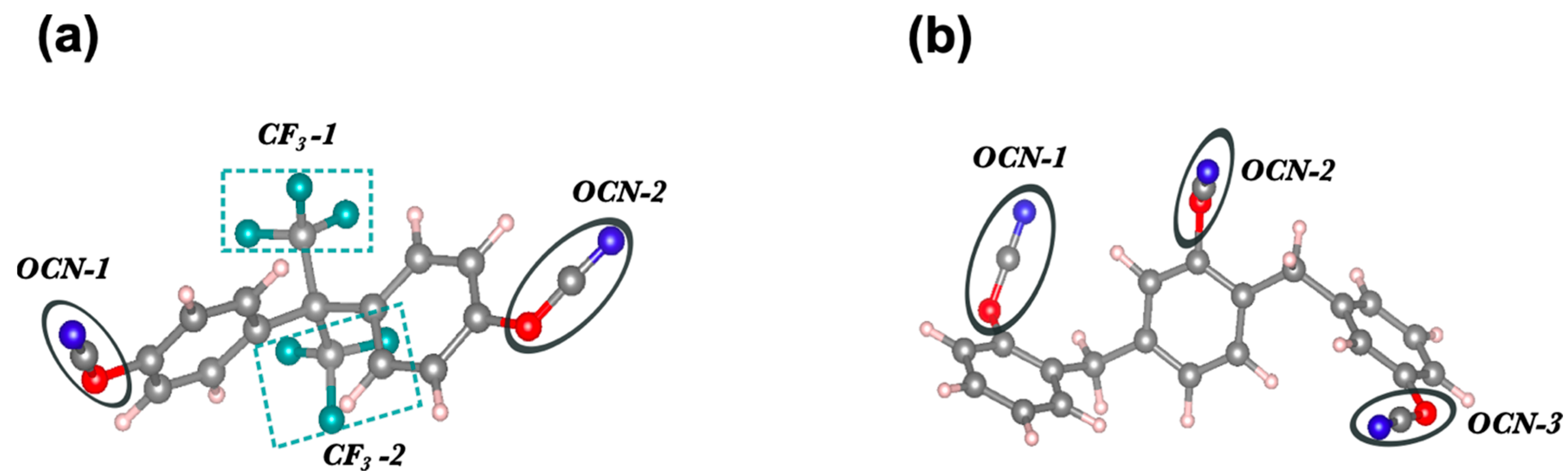
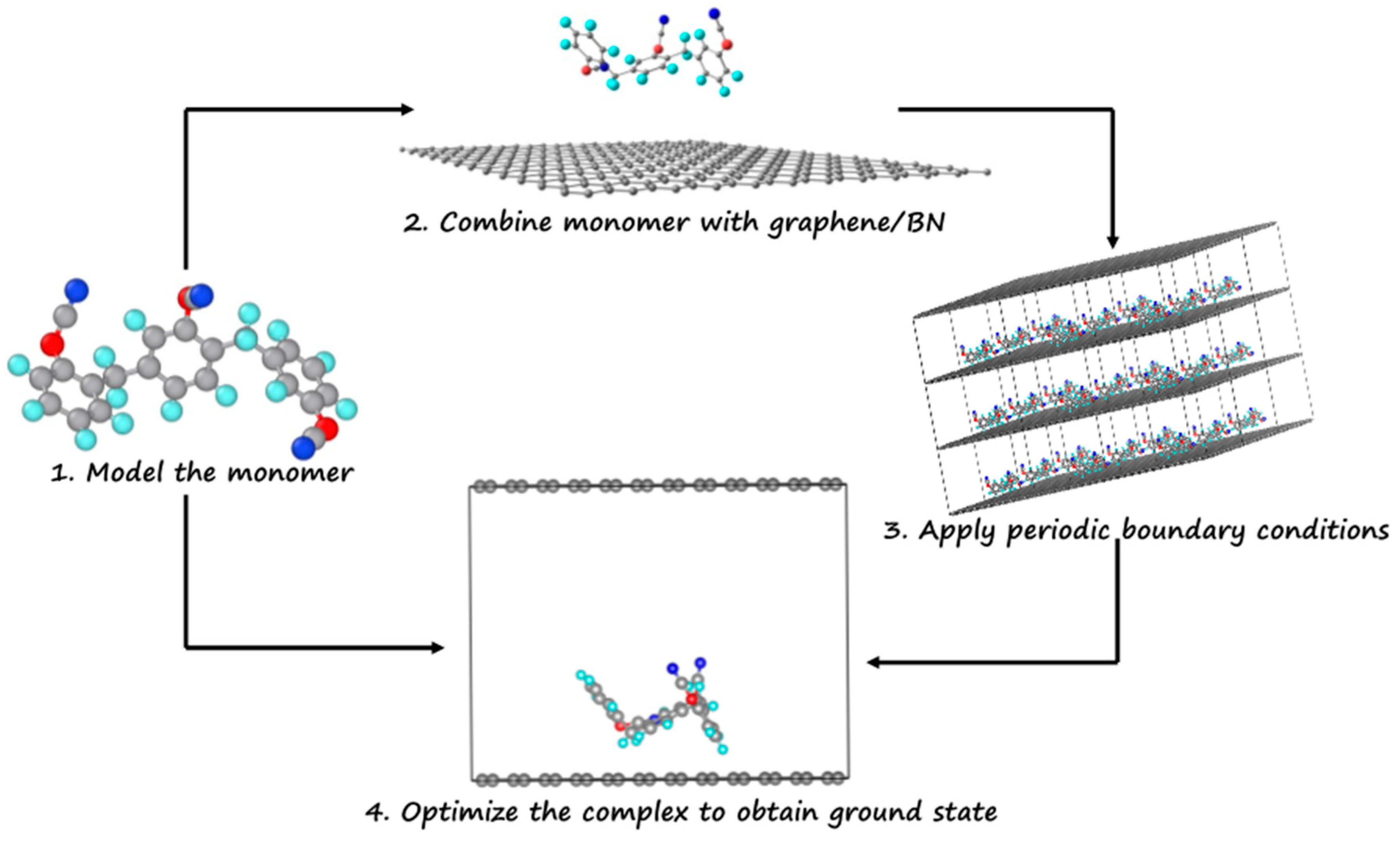
2. Computational Details

The Vienna Ab-initio Simulation Package (VASP) [22] was used to perform DFT calculations utilizing projector augmented wave (PAW) [23] potentials. The Perdew, Burke, and Ernzerhof (PBE) parameterization of the generalized gradient approximation (GGA) was employed for the exchange-correlation functional [24], and van der Waals interactions were incorporated using Grimme’s D2 technique [25]. Additionally, we used a Γ-centered k-point grid with a plane-wave cutoff of 500 eV and convergence criterion of 10−5 eV for energy. The conjugate gradient (CG) algorithm was used to fully relax local energy-minimum structures with atoms with forces smaller than 0.001 eV/Å.
We employed a 30 Å × 30 Å × 20 Å supercell and applied the periodic boundary conditions to mimic the system as a non-polymerized composite system. To ensure that periodic images do not interfere with each other, a vacuum of 20 Å has been applied along the z-axis. The monomer is placed on top of the monolayer at a distance of ~2.5 Å, i.e., slightly higher than the nearest monomer and monolayer atoms van der Waal radii [26]. Then, the geometry optimization was performed to find the equilibrium configuration of the ester/graphene (or BN monolayer) complex.
The commonly used “pull-apart” experimental setup was utilized to determine the complex’s mechanical response [27,28,29,30]. The pull-apart simulation setup schematic to derive the force–strain relationship is shown in Figure S1 (Supporting Information (SI)). At first, starting from an optimized geometry, the monomer moves away perpendicularly to the monolayer surface with a step size of ≈0.02 Å. The calculated variation in energy as a function of each incremental step referred to as (out-of-the-plane) transverse strain is shown in Figure S2 (SI). This is how the transverse strain, ε, is defined as ε = (ll0)/l0, where l represents the distance of the monomer from the surface for a given step, and l0 represents the distance in the equilibrium configuration for the complex. It is noteworthy that the equilibrium distance l0 is the distance between the nearest atoms of the monomer and the monolayer. Also, the associated change in the energy is defined as Es = E(ε) − E(0), with E(0) being the energy related to the equilibrium configuration. Note that the configuration optimization of the monomer is not performed at each step as it moves away from the surface. The strain-energy data is then obtained by moving one component (monomer) of the complex in one dimension (z-axis).
A force–strain curve, derived from the derivative of the strain-energy curve, is used to calculate the mechanical response of the complex. The one-dimensional spinodal equation of state (1D SEOS) is fitted to the force–strain curve to calculate the critical strain and force [10,31]. The detailed derivation of 1D SEOS is given in reference [31], where the authors have studied the uniaxial strain of a layered compound using density functional theory. Moreover, the spinodal equation of state has been successfully applied to investigate the mechanical response of low-dimensional materials [10,19,32,33].
The SEOS can be stated as:
σ = σ s p 1 ϵ s p ϵ ϵ s p 1 1 γ
The stress and strain are analytically related, as shown in Equation (1), where σ s p , ϵ s p represent spinodal stress and strain, and σ , ϵ represent stress and strain at a particular point, respectively. The fitting parameter γ is an exponent whose value depends on the strain’s (stretching or compressing) direction.
At isothermal 0 K, the force can be derived using equilibrium length L, and the internal energy E via the relationship f = 1 L d E d ϵ . Knowing the stress given by Equation (1) and the effective contact area at the interface, the spinodal equation for force can then be written as
f = f s p 1 ϵ s p ϵ ϵ s p 1 1 γ
where f s p (spinodal force or critical force) is represented as the maximum force required for the system to break and, hence, indicates the material’s breaking point, referred to as the critical strain ( ϵ sp or ϵ c).
In this work, we designate critical strain as the transverse strain or separation point. Similarly, critical strength refers to the system’s transverse strength. Furthermore, the proposed state equation can be represented analytically in its energy form. Overall, this appears to be a preliminary step to relate the molecular description of the interface obtained from the first-principles method to the macroscopic mechanical response of the system via the 1D SEOS for the ester monomers interacting with graphene or BN monolayer.

3. Results and Discussion

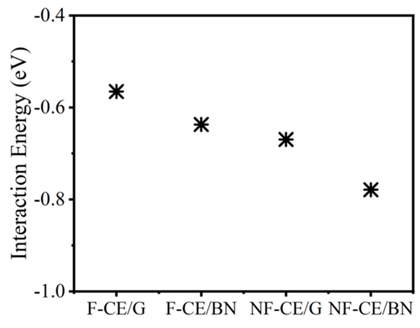
3.1. Interaction Energy

Figure 2 illustrates how the molecular-level description of the ester–monolayer complex was obtained. First, the ground-state configurations of fluorinated and non-fluorinated monomers were obtained (Table S1 (SI)). Next, the monomer in an in-plane configuration was approached perpendicularly to the surface while keeping the monolayer configuration fixed. It is to be noted that in our previous study of epoxy/BMI monomers interacting with a graphene (or BN) monolayer, a detailed conformational sampling in terms of the orientation of a monomer approaching the surface was investigated [10]. The in-plane orientation was anticipated to be the energetically preferable orientation of the monomer on a surface out of four representative orientations: flip-up, flip-in, vertical, and in-plane. The findings were likewise validated in terms of contact area and atom population at the surface. Compared to the flip-up, flip-in, and vertical orientations, the in-plane orientation has the highest population of atoms and interaction energy [10]. Next, the interaction energy for the representative orientations of fluorinated ester monomer with graphene monolayer was calculated to validate the case for ester monomer. Energy analysis revealed that in-plane orientation is the most favorable orientation (Figure S3 (SI)). Furthermore, a preference for the longitudinal configuration of monomer over CNT was obtained over the transverse configuration [34].
Following that, the properties such as interaction energy, the effective area of contact, the population of atoms, density of states, and Bader’s charge [32] were calculated to characterize the interface formed by ester monomers with a graphene (or BN) monolayer. The population of atoms is defined as the number of monomer atoms within a distance of 3 Å from the surface. The contact area is the effective area projected by the monomer on the surface of a graphene (or BN) monolayer. By measuring the width and length of the monomer-covered surface, we could compute the effective area of contact. It should be noted that the interplanar distance in the vdW complexes, which includes the monomer–monolayer system under consideration, is reported to be ~3 Å [34]. The interaction energy is defined as E = EcomplexEmonomerEmonolayer, where a negative value of E indicates the complex is stable (Figure 3, Table 1).
BN/monomer interactions are stronger than those produced with the graphene due to the polar-π interactions between a polar surface of the BN monolayer and the π system of the monomer [35,36,37]. In contrast, the interaction strength of graphene/ester monomer complexes is governed only by the templating effect [38] of the phenyl groups interacting with a graphitic surface. Note that aromatic rings prefer to align themselves parallel to the surface, forming the π-π stacked configurations [33]. DFT calculations also predict relatively higher stability for the non-fluorinated monomer than the fluorinated monomer (see Figure 3). This effect is associated with the larger area of contact of the non-fluorinated ester (≈102 Å2) compared to the fluorinated ester (≈95 Å2), leading to an increase in the vdW interactions at the interface. The area of contact for a non-fluorinated ester is relatively large due to the presence of an additional phenyl ring and cyanate group.
This has been affirmed by the population of atoms as well, which is higher for non-fluorinated ester than fluorinated ester monomers (Table 1). Likewise, the calculated values of the area of contact normalized interaction energy show that non-fluorinated ester interacting with graphene has a higher interaction energy per unit area (−0.007 eV/Å2) than fluorinated ester (−0.006 eV/Å2). Furthermore, the -CF3 group of the fluorinated ester induces steric hindrance effects, which may restrict the parallel alignment of the monomer on the surface. This effect has been noted in previous studies of the other fluorinated polymers and CNTs functionalized with fluorine atoms [39,40,41].
To determine whether charge transfer occurs between the constituents in the complex, we now perform Bader’s charge analysis. In both cases, a small charge transfer (<0.1 e) occurred from the graphene (or BN) monolayer to the monomer (Table 1). It then rules out the dominance of the electrostatic interactions at the interface. Furthermore, the electronic density of states (DOS) of the ester complex shows that the DOS of the ester complex is nearly a superposition of the DOS of the individual components (see Figure S4, SI). Moreover, ester monomers do not modify the behavior of the DOS near the Fermi level, suggesting that the interaction at the interface is dominated by the weak vdW forces. Note that Figure S4 presents the density of states (DOS) for graphene/BN, and the monomer corresponds to the isolated components, not projected states.
Consequently, the dipole moments of the fluorinated and non-fluorinated ester monomers are predicted as 2.61 Debye and 6.2 Debye, respectively. A relatively high dipole moment of the non-fluorinated monomer, in turn, provides relatively high flexibility in the electronic density, thus facilitating higher vdW interactions at the interface. Ultimately, the results predict that the interface of the ester complexes will be dominated by the noncovalent interactions. However, because of the semi-ionic behavior of the BN, we found a small but remarkable difference in the interaction energies of when compared to graphene complexes: Einteraction(AroCy F-10(graphene)) < Einteraction(AroCy F-10(BN)) and Einteraction(Primaset PT-30(graphene)) < Einteraction(Primaset PT-30 (BN)).

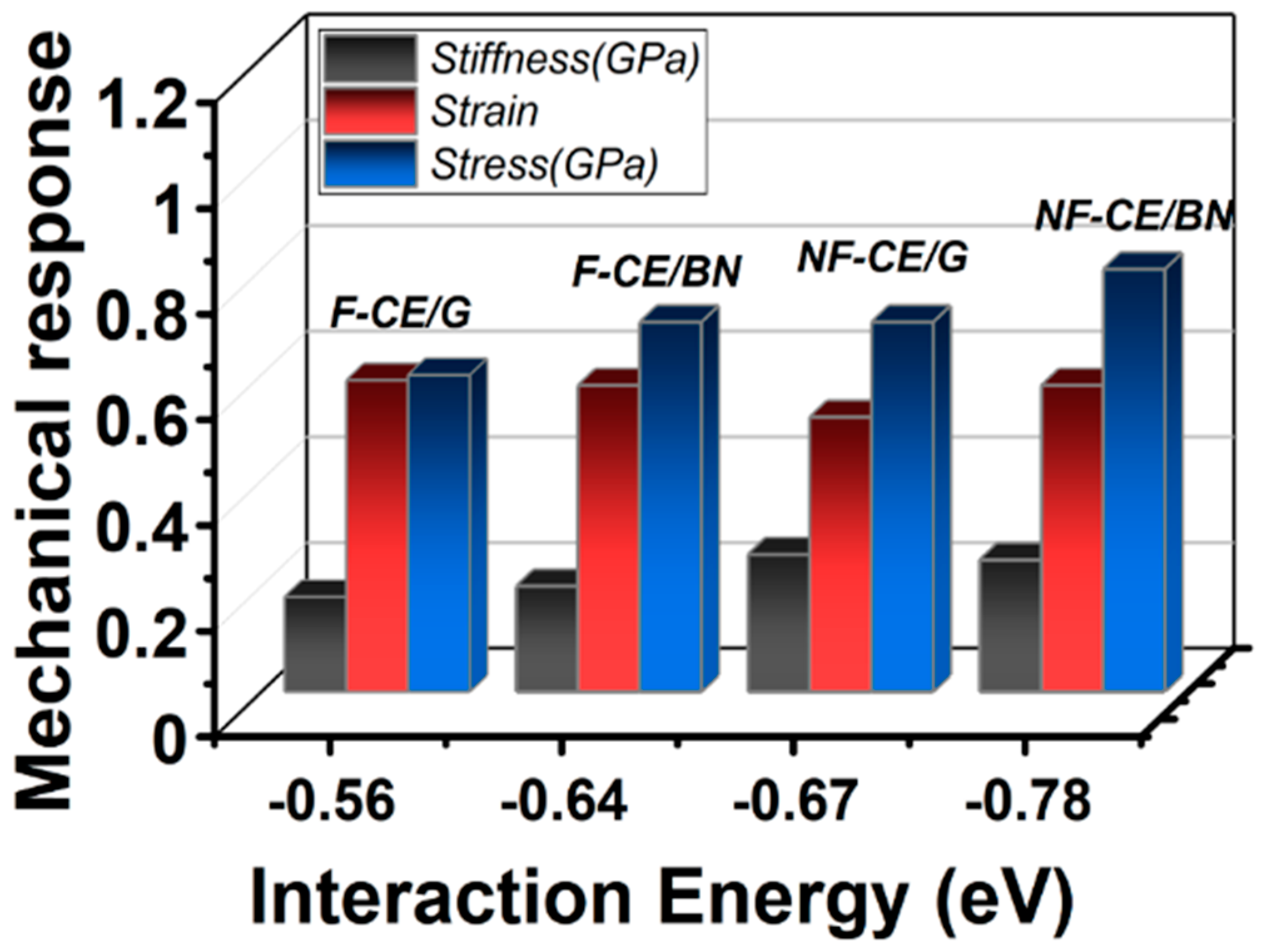
3.2. Mechanical Response

The mechanical properties (out-of-plane) of the ester complexes were predicted in terms of critical force (transverse strength), transverse stress, transverse stiffness, and critical strain using the pull-apart setup. In the simulation, an ester monomer was displaced in small steps (≈0.02 Å) normal to the graphene (or BN) surface, starting from its optimized state (equilibrium distance) until ≈3.8 Å of separation (Figure 4, inset). We note that the H atoms of the ester monomers are the nearest-neighbor atoms for the graphene (or BN) monolayer (Figure S5 (SI)). The critical force calculated during the pull-apart process at various strain points can accurately determine the critical stress and strain.
The point at which the separation occurs is the point of maximum interaction between the monomer and surface and can be called the separation point. Moreover, if further strain is applied to the complex, the force will decrease until it vanishes, indicating that the applied external force has overcome the mechanical strength at the interface of the complex.
Applying the 1D SEOS allows us to derive transverse strength and separation point values for the ester complexes based on the associated fitting parameters σsp, ϵ sp, respectively (Table S2 (SI)). Furthermore, it is important to note that the pseudocritical exponent (i.e., γ) varies between 0.5 and 0.8 (Table S2 (SI)) for the ester complexes within the stretching region of the spinodal stress–strain equation of state. For a solid under high pressure, γ is reported to be 0.85 [42]. On the other hand, the lower values of γ (~0.5) [31] are attributed to the stretching region of the curve.
Table 2 shows the computed transverse stiffness as well as separation point values, which are used to describe the mechanical behavior of the ester complexes. According to our findings, the non-fluorinated ester has a higher transverse strength than the fluorinated ester, with the hierarchical order being AroCy F-10(graphene) < AroCy F-10(BN) < Primaset PT-30(graphene) < Primaset PT-30 (BN). Interestingly, the fluorinated ester is predicted to have a relatively higher separation point than the non-fluorinated ester, enhancing its interfacial load transfer. This fact can be attributed to the influence of fluorine atoms, which cause steric hindrance and interlocking effects in the fluorinated case. Hence, it prevents its separation against the surface, as reported previously [39,40,41].
Figure 5 displays the relationship between the interaction strength and the mechanical response of cyanate ester complexes in terms of transverse stress and stiffness. A stress–strain curve is given in Figure S6 (SI), and Table S2 (SI) lists the calculated values for which the effective contact area was estimated by utilizing the length and width covered by the ester monomer over the graphene (or BN) monolayer. The results predict that the non-fluorinated ester complexes are stiffer than the fluorinated ester complexes, following the order obtained for the interaction energy values (Table 1). Given that (out-of-plane) stiffness is related to quasi-3D Young’s modulus, a relatively high stiffness value results in a higher Young’s modulus at the interface, one of the polymer composite’s useful features for structural and aerospace applications. It is significant to mention that the calculated separation point values of the cured fluorinated/flCNT and non-fluorinated/flCNT are predicted to be 0.6 and 1.1, respectively, by employing the Polymer Consistent Force Field–Interface Force Field (PCFF-IFF) model in molecular dynamics (MD) computations [43].

4. Summary

A state-of-the-art DFT simulation is used to analyze the interfacial properties of fluorinated and non-fluorinated cyanate esters forming complexes with a graphene (or BN) monolayer. We find that the nature of the interface depends on the specific monomer configuration, with the non-fluorinated monomer markedly possessing a higher degree of interaction with the graphene (or BN) monolayer than the fluorinated monomer. This leads to a smaller transverse strength but a higher separation point for the fluorinated ester, which can be explained by the stronger steric hindrance provided by the fluorine groups at the interface. Despite the limited flexibility of the fluorinated ester, which reduces the interaction energy, it appears to provide mechanical interlocking that increases the transverse strain at the interface. Therefore, the present study has enabled us to elucidate the properties at the molecular level that are difficult to determine by experiments. Moreover, we show that the BN-based ester complexes are likely to have a higher mechanical strength than those based on graphene and, thus, can be considered structural materials in aerospace vehicles.

Supplementary Materials

The following supporting information can be downloaded at: https://www.mdpi.com/article/10.3390/ma17010108/s1, Table S1: Some of the representative structural parameters of the fluorinated and non-fluorinated cyanate ester monomers; Table S2: Calculated mechanical response in terms of Transverse strength, (out-of-plane) Separation point, Transverse stress, Stiffness, and fitting constant γ of the monomer complexes; Figure S1: Schematic of force-strain relationship during pull-apart mechanism, where the monomer complex separates into its constituents at the point of maximum force. A solid geometry represents the monomer complex in the figure; Figure S2: The calculated strain-energy relationship of the fluorinated (F-CE) and non-fluorinated cyanate ester (NF-CE) interacting with graphene (G) and BN monolayer. Zero is taken to be the equilibrium configuration, and dE is the energy with respect to the total energy of the equilibration configuration; Figure S3: Orientation dependent interaction energy for flourinated cyanate ester monomer with graphene monolayer; Figure S4: Calculated total density of states and density of states for monomers forming composites with graphene or BN monolayer: (a) fluorinated ester/graphene, (b) non-fluorinated ester/graphene, (c) fluorinated ester/BN, (d) non-fluorinated ester/BN. The inset shows DOS contributions from the corresponding monomers in the complexes; Figure S5: The distances between the atoms of the fluorinated and non-fluorinated ester monomer with nearest C atom of graphene and nearest B or N atom of BN monolayer; Figure S6: Calculated Transverse stress vs. Transverse strain curve for the fluorinated (F-CE) and non-fluorinated cyanate ester (NF-CE) forming complexes with graphene (or BN monolayer) [44].

Author Contributions

Conceptualization, Á.L.; Methodology, G.S.; Investigation, G.S.; Writing—original draft, G.S.; Supervision, R.P.; Writing—Review and Editing, R.P.; Resources, R.P.; Project administration, G.M.O.; Funding acquisition, G.M.O. All authors have read and agreed to the published version of the manuscript.

Funding

This research received funding from the NASA Space Technology Research Institute (STRI) for Ultra-Strong Composites by Computational Design (US-COMP), Grant NNX17AJ32G, and the Spanish National Research Agency (AEI) through project PGC2018-094814-B-C22.

Institutional Review Board Statement

Not applicable.

Informed Consent Statement

Not applicable.

Data Availability Statement

All data generated or analyzed during this study are included in this published article. For more inquiries, contact the corresponding author at [email protected].

Acknowledgments

The authors would like to thank J. M. Recio, S. Gowtham, M. Seel, and Cameron Shock for their helpful discussions.

Conflicts of Interest

The authors declare no conflict of interest.

References

  1. Nayak, N.V. Composite materials in aerospace applications. Int. J. Sci. Res. Publ. 2014, 4, 1–10. [Google Scholar]
  2. Kesarwani, S. Polymer composites in the aviation sector. J. Int. J. Eng. Res. Technol. 2017, 6, 518–525. [Google Scholar] [CrossRef]
  3. Rana, S.; Fangueiro, R. Advanced composites in aerospace engineering. In Advanced Composite Materials for Aerospace Engineering; Elsevier: Amsterdam, The Netherlands, 2016; pp. 1–15. [Google Scholar]
  4. Available online: https://www.nasa.gov/offices/oct/home/roadmaps/index.html (accessed on 20 August 2021).
  5. Kinloch, I.A.; Suhr, J.; Lou, J.; Young, R.J.; Ajayan, P.M. Composites with carbon nanotubes and graphene: An outlook. Science 2018, 362, 547–553. [Google Scholar] [CrossRef]
  6. Downes, R.D.; Hao, A.; Park, J.G.; Su, Y.F.; Liang, R.; Jensen, B.D.; Siochi, E.J.; Wise, K.E. Geometrically constrained self-assembly and crystal packing of flattened and aligned carbon nanotubes. Carbon 2015, 93, 953–966. [Google Scholar] [CrossRef]
  7. Zhang, X.; Li, Q.; Holesinger, T.G.; Arendt, P.N.; Huang, J.; Kirven, P.D.; Clapp, T.G.; DePaula, R.F.; Liao, X.; Zhao, Y.; et al. Ultrastrong, stiff, and lightweight carbon-nanotube fibers. Adv. Mater. 2007, 19, 4198–4201. [Google Scholar] [CrossRef]
  8. Papageorgiou, D.G.; Kinloch, I.A.; Young, R.J. Mechanical properties of graphene and graphene-based nanocomposites. Prog. Mater. Sci. 2017, 90, 75–127. [Google Scholar] [CrossRef]
  9. Choi, D.; Wang, Q.; Azuma, Y.; Majima, Y.; Warner, J.H.; Miyata, Y.; Shinohara, H.; Kitaura, R. Fabrication and characterization of fully flattened carbon nanotubes: A new graphene nanoribbon analogue. Sci. Rep. 2013, 3, 1617. [Google Scholar] [CrossRef]
  10. Sachdeva, G.; Lobato, A.; Pandey, R.; Odegard, G.M. Mechanical Response of Polymer Epoxy/BMI Composites with Graphene and a Boron Nitride Monolayer from First Principles. ACS Appl. Polym. Mater. 2021, 3, 1052–1059. [Google Scholar] [CrossRef]
  11. Ottiger, P.; Pfaffen, C.; Leist, R.; Leutwyler, S.; Bachorz, R.A.; Klopper, W. Strong N−H··· π hydrogen bonding in amide− benzene interactions. J. Phys. Chem. B 2009, 113, 2937–2943. [Google Scholar] [CrossRef]
  12. Kandelbauer, A. Cyanate ester resins. In Handbook of Thermoset Plastics; Elsevier: Amsterdam, The Netherlands, 2022; pp. 587–617. [Google Scholar]
  13. Wooster, T.J.; Abrol, S.; Hey, J.M.; MacFarlane, D.R. Thermal, mechanical, and conductivity properties of cyanate ester composites. Compos. Part A Appl. Sci. Manuf. 2004, 35, 75–82. [Google Scholar] [CrossRef]
  14. Nair, C.R.; Mathew, D.; Ninan, K. Cyanate ester resins, recent developments. In New Polymerization Techniques and Synthetic Methodologies; Springer: Berlin/Heidelberg, Germany, 2001; pp. 1–99. [Google Scholar]
  15. Hamerton, I.; Hay, J.N. Recent technological developments in cyanate ester resins. High-Perform. Polym. 1998, 10, 163–174. [Google Scholar] [CrossRef]
  16. Brand, R.; Harrison, E. Development of Tough, Moisture Resistant Laminating Resins; General Dynamics Convair Div: San Diego, CA, USA, 1982. [Google Scholar]
  17. Fang, T.; Shimp, D.A. Polycyanate esters: Science and applications. Prog. Polym. Sci. 1995, 20, 61–118. [Google Scholar] [CrossRef]
  18. Hamerton, I. Chemistry and Technology of Cyanate Ester Resins; Springer Science & Business Media: Berlin/Heidelberg, Germany, 2012. [Google Scholar]
  19. Henkelman, G.; Arnaldsson, A.; Jónsson, H. A fast and robust algorithm for Bader decomposition of charge density. Comput. Mater. Sci. 2006, 36, 354–360. [Google Scholar] [CrossRef]
  20. Zhong, X.; Yap, Y.K.; Pandey, R.; Karna, S.P. First-principles study of strain-induced modulation of energy gaps of graphene/BN and BN bilayers. Phys. Rev. B 2011, 83, 193403. [Google Scholar] [CrossRef]
  21. Hod, O. Graphite and hexagonal boron-nitride have the same interlayer distance. Why? J. Chem. Theory Comput. 2012, 8, 1360–1369. [Google Scholar] [CrossRef]
  22. Kresse, G.; Joubert, D. From ultrasoft pseudopotentials to the projector augmented-wave method. Phys. Rev. B 1999, 59, 1758. [Google Scholar] [CrossRef]
  23. Blöchl, P.E. Projector augmented-wave method. Phys. Rev. B 1994, 50, 17953. [Google Scholar] [CrossRef]
  24. Perdew, J.P.; Burke, K.; Ernzerhof, M. Generalized gradient approximation made simple. Phys. Rev. Lett. 1996, 77, 3865. [Google Scholar] [CrossRef]
  25. Grimme, S. Semiempirical GGA-type density functional constructed with a long-range dispersion correction. J. Comput. Chem. 2006, 27, 1787–1799. [Google Scholar] [CrossRef]
  26. Grabowski, S.J.; Sokalski, W.A.; Dyguda, E.; Leszczyński, J. Quantitative classification of covalent and noncovalent H-bonds. J. Phys. Chem. B 2006, 110, 6444–6446. [Google Scholar] [CrossRef]
  27. Chandra, Y.; Scarpa, F.; Adhikari, S.; Zhang, J.; Flores, E.S.; Peng, H.X. Pullout strength of graphene and carbon nanotube/epoxy composites. Compos. Part B Eng. 2016, 102, 1–8. [Google Scholar] [CrossRef]
  28. Barber, A.H.; Cohen, S.R.; Wagner, H.D. Measurement of carbon nanotube-polymer interfacial strength. Appl. Phys. Lett. 2003, 82, 4140–4142. [Google Scholar] [CrossRef]
  29. Cooper, C.A.; Cohen, S.R.; Barber, A.H.; Wagner, H.D. Detachment of nanotubes from a polymer matrix. Appl. Phys. Lett. 2002, 81, 3873–3875. [Google Scholar] [CrossRef]
  30. DiFrancia, C.; Ward, T.C.; Claus, R.O. The single-fiber pull-out test. 1: Review and interpretation. Compos. Part A Appl. Sci. Manuf. 1996, 27, 597–612. [Google Scholar] [CrossRef]
  31. Chorfi, H.; Lobato, Á.; Boudjada, F.; Salvadó, M.A.; Franco, R.; Baonza, V.G.; Recio, J.M. Computational modeling of tensile stress effects on the structure and stability of prototypical covalent and layered materials. Nanomaterials 2019, 9, 1483. [Google Scholar] [CrossRef]
  32. Tang, W.; Sanville, E.; Henkelman, G. A Grid-Based Bader Anal. Algorithm Without Lattice Bias. J. Phys. Condens. Matter 2009, 21, 084204. [Google Scholar] [CrossRef]
  33. Nasrabadi, A.T.; Foroutan, M. Interactions between polymers and single-walled boron nitride nanotubes: A molecular dynamics simulation approach. J. Phys. Chem. B 2010, 114, 15429–15436. [Google Scholar] [CrossRef]
  34. Gou, J.; Fan, B.; Song, G.; Khan, A. Study of affinities between the single-walled nanotube and epoxy resin using molecular dynamics simulation. Int. J. Nanosci. 2006, 5, 131–144. [Google Scholar] [CrossRef]
  35. Cozzi, F.; Ponzini, F.; Annunziata, R.; Cinquini, M.; Siegel, J.S. Polar Interactions between Stacked π Systems in Fluorinated 1, 8-Diarylnaphthalenes: Importance of Quadrupole Moments in Molecular Recognition. Angew. Chem. Int. Ed. Engl. 1995, 34, 1019–1020. [Google Scholar] [CrossRef]
  36. Hunter, C.A.; Sanders, J.K. The nature of. pi.-. pi. Interactions. J. Am. Chem. Soc. 1990, 112, 5525–5534. [Google Scholar] [CrossRef]
  37. Anslyn, E.V.; Dougherty, D.A. Modern Physical Organic Chemistry; University Science Books: Melville, NY, USA, 2006. [Google Scholar]
  38. Sinnokrot, M.O.; Valeev, E.F.; Sherrill, C.D. Estimates of the ab initio limit for π−π interactions: The benzene dimer. J. Am. Chem. Soc. 2002, 124, 10887–10893. [Google Scholar] [CrossRef]
  39. Lv, C.; Xue, Q.; Xia, D.; Ma, M.; Xie, J.; Chen, H. Effect of chemisorption on the interfacial bonding characteristics of graphene-polymer composites. J. Phys. Chem. C 2010, 114, 6588–6594. [Google Scholar] [CrossRef]
  40. Liang, Y.-Y.; Xu, J.Z.; Liu, X.Y.; Zhong, G.J.; Li, Z.M. Role of surface chemical groups on carbon nanotubes in nucleation for polymer crystallization: Interfacial interaction and steric effect. Polymer 2013, 54, 6479–6488. [Google Scholar] [CrossRef]
  41. Castner, D.G.; Grainger, D.W. Fluorinated Surfaces, Coatings, and Films; ACS Publications: Washington, DC, USA, 2001. [Google Scholar]
  42. Brosh, E.; Makov, G.; Shneck, R.Z. The spinodal constraint on the equation of state of expanded fluids. J. Phys. Condens. Matter 2003, 15, 2991. [Google Scholar] [CrossRef]
  43. Pisani, W.A.; Radue, M.S.; Patil, S.U.; Odegard, G.M. Interfacial modeling of flattened CNT composites with cyanate ester and PEEK polymers. Compos. Part B Eng. 2021, 211, 108672. [Google Scholar] [CrossRef]
  44. Kresse, G.; Gil, A.; Sautet, P. Significance of single-electron energies for the description of CO on Pt (111). Phys. Rev. B 2003, 68, 073401. [Google Scholar] [CrossRef]
Figure 1. Molecular Representation of (a) AroCy-F10 (Fluorinated) and (b) Primaset PT-30 (Non-Fluorinated) Cyanate Ester Resin Monomers: Ball and Stick Models with Ester and Fluorine Groups Highlighted. Color codes: C—grey, H—white, N—blue, F—green, O—red.
Materials 17 00108 g001
Figure 2. A workflow diagram describing the steps taken to determine the equilibrium structure of the monomer/graphene complex. Color codes: C—grey, H—white, N—blue, F—green, O—red.
Materials 17 00108 g002
Figure 3. The calculated interaction energy of the ester resins: AroCy-F10 (fluorinated cyanate ester), labeled as F-CE, and Primaset PT-30 (non-fluorinated cyanate ester), labeled as NF-CE. G refers to graphene, and BN refers to a boron nitride monolayer.
Materials 17 00108 g003
Figure 4. Calculated force vs. transverse strain curve of the ester/monolayer; AroCy-F10 (fluorinated cyanate ester) labeled as F-CE and Primaset PT-30 (non-fluorinated cyanate ester) labeled as NF-CE. G refers to graphene, and BN refers to a BN monolayer.
Materials 17 00108 g004
Figure 5. Calculated mechanical response and the interaction energy of the ester complexes; AroCy-F10 (fluorinated cyanate ester) labeled as F-CE and Primaset PT-30 (non-fluorinated cyanate ester) labeled as NF-CE. Also, G refers to graphene, and BN refers to a BN monolayer.
Materials 17 00108 g005
Table 1. The computed interaction energy (ΔE), the population of atoms, and Bader’s charge (Q) for AroCy-F10 (F-CE) and Primaset PT-30 (NF-CE) interacting with graphene (or BN) monolayer.
Complex∆E
(eV)
Population (%)Q (e)
GrapheneAroCy-F10 (F-CE)−0.5611.40.03
GraphenePrimaset PT-30 (NF-CE)−0.6713.60.04
BN monolayerAroCy-F10 (F-CE)−0.6411.40.04
BN monolayerPrimaset PT-30 (NF-CE)−0.7813.60.04
Table 2. Predicted (out-of-plane) separation point, and transverse strength of the fluorinated and non-fluorinated cyanate ester complexes formed with graphene (or BN) monolayer.
Complex(Out-of-Plane)
Separation Point εc (%)
Transverse Strength fc (nN)
GrapheneAroCy-F10 (fluorinated)5.9 ± 0.30.57 ± 0.01
GraphenePrimaset PT-30 (non-fluorinated)5.2 ± 0.30.71 ± 0.03
BN monolayerAroCy-F10 (fluorinated)6.4 ± 0.20.63 ± 0.01
BN monolayerPrimaset PT-30 (non-fluorinated)5.8 ± 0.30.80 ± 0.02
Disclaimer/Publisher’s Note: The statements, opinions and data contained in all publications are solely those of the individual author(s) and contributor(s) and not of MDPI and/or the editor(s). MDPI and/or the editor(s) disclaim responsibility for any injury to people or property resulting from any ideas, methods, instructions or products referred to in the content.

