
Comparative Study on Laser Welding Thick-Walled TC4 Titanium Alloy with Flux-Cored Wire and Cable Wire


 ,
,  and
and
Abstract
:1. Introduction
2. Materials and Methods
2.1. Meterials
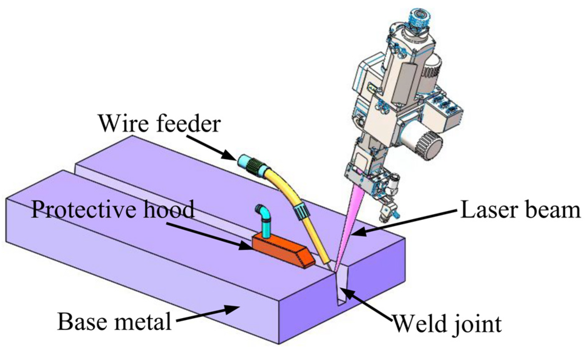
2.2. Methods
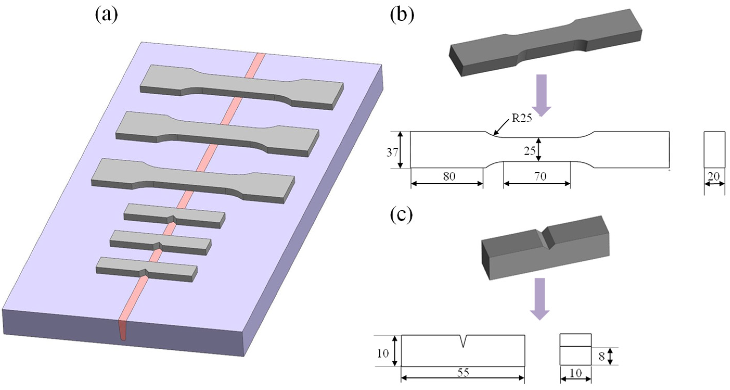
2.3. Sample Preparation and Characterization
3. Results and Discussion
3.1. Microstructural Comparison
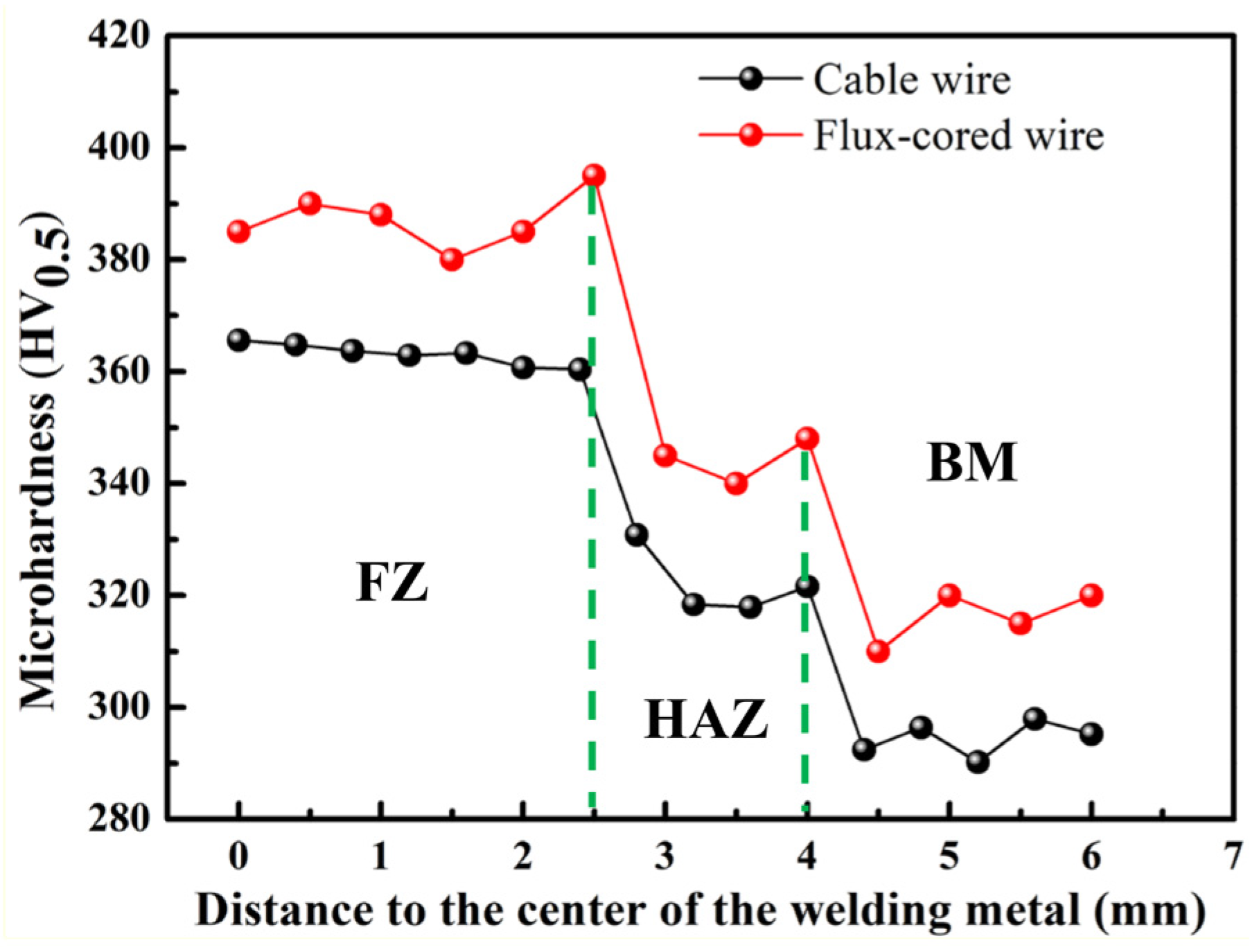
3.2. Mechanical Property Comparison
4. Conclusions
- (1)
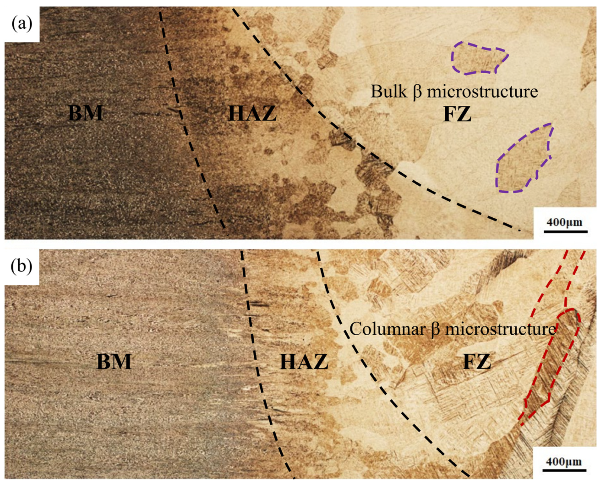
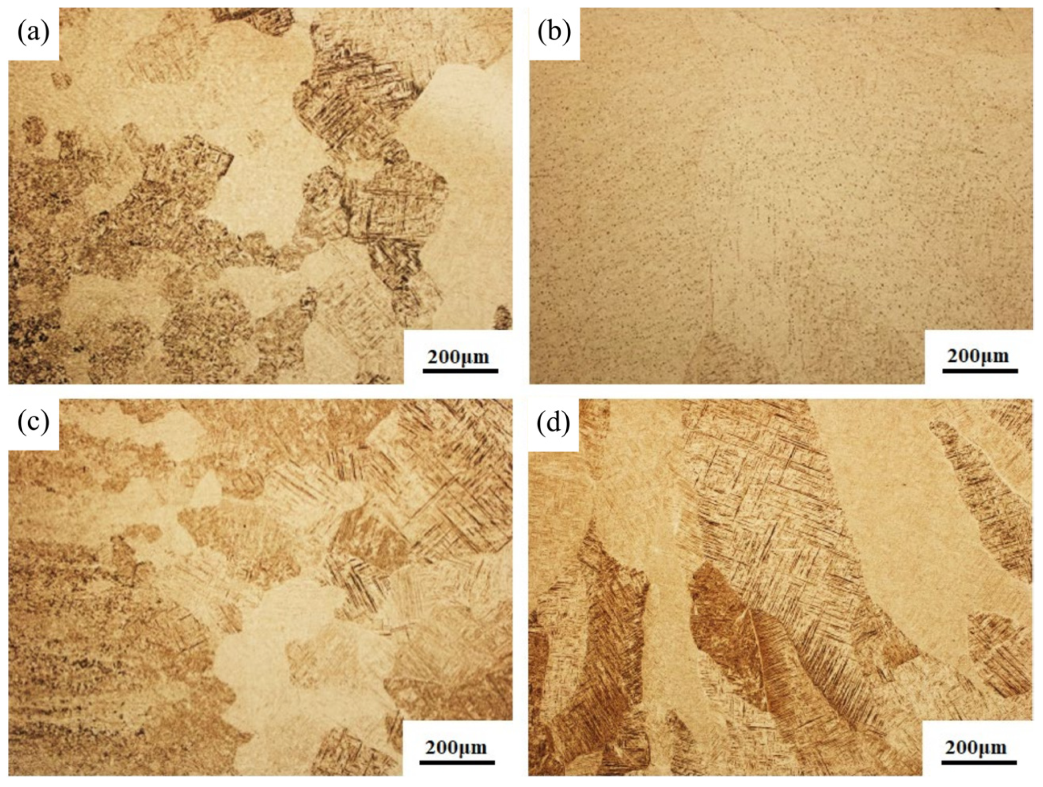
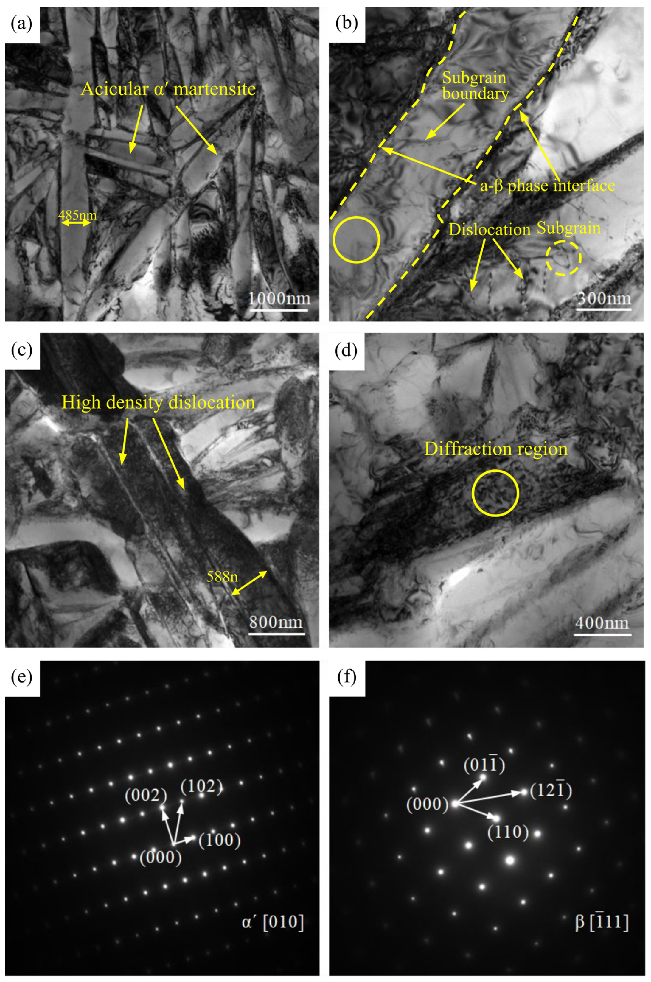
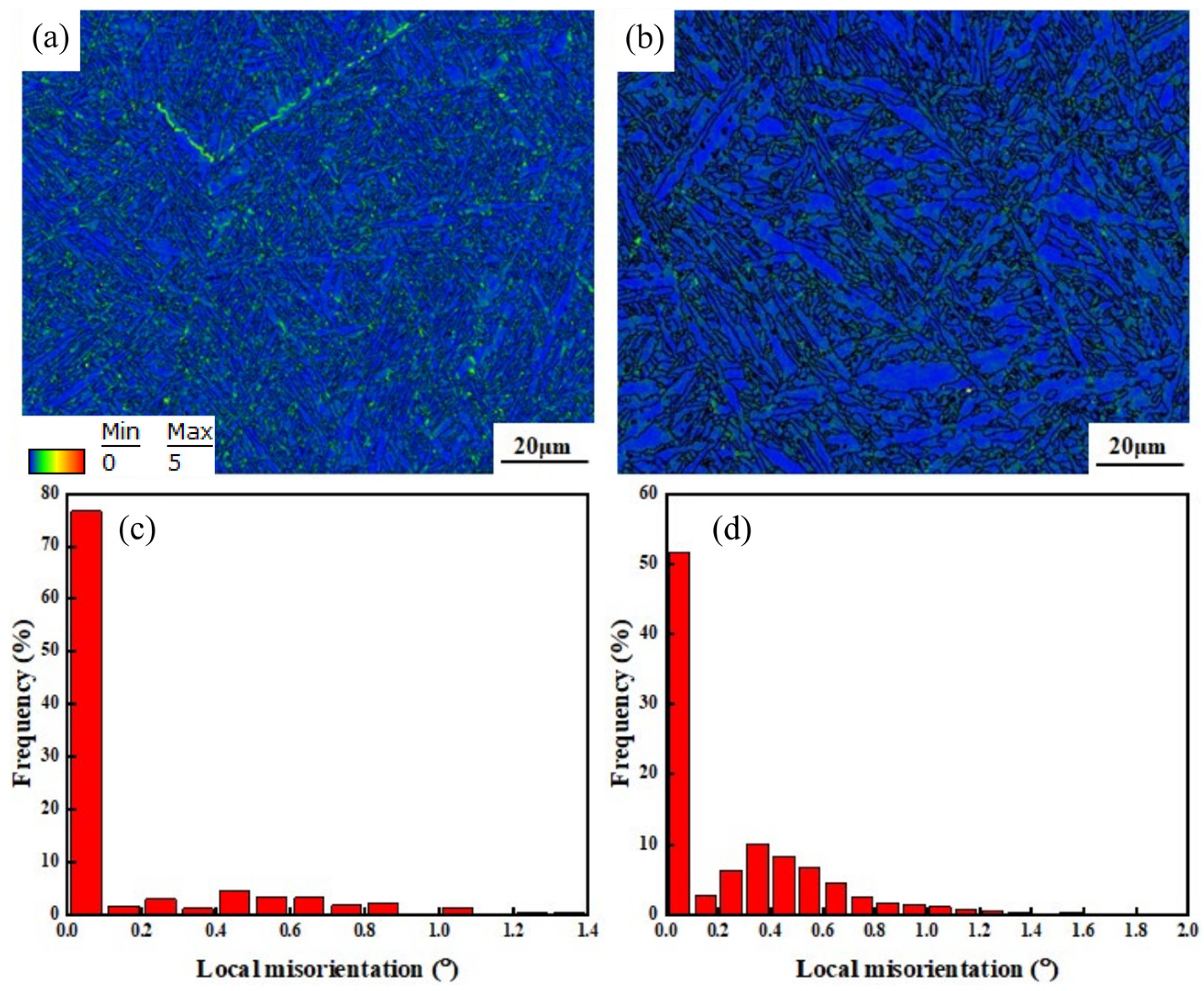
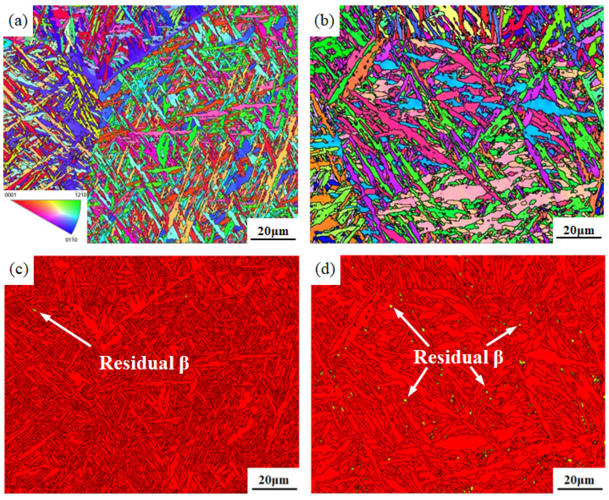
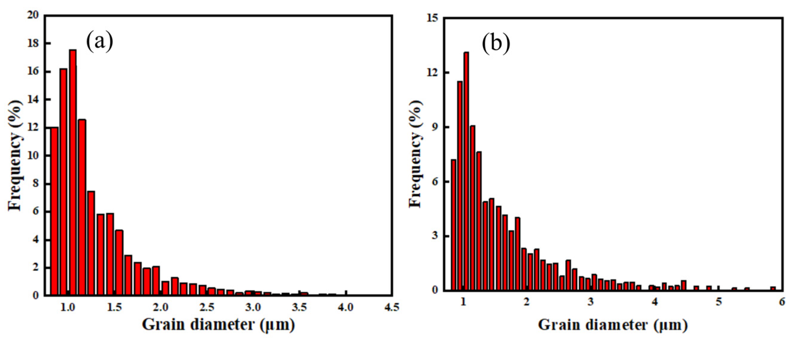
- A coarse β microstructure can be observed in the two welded joints. The basketweave structure consists of a large amount of interwoven acicular α′ martensite, which is dominant in the β microstructure. The β microstructure in the joint welded with flux-cored wire presents with blocky polygonal morphology, whereas the β microstructure in the joint welded with cable wire shows a coarse columnar dendrite morphology with more typical and stronger internal acicular α′ martensite and more obvious directionality.
- (2)
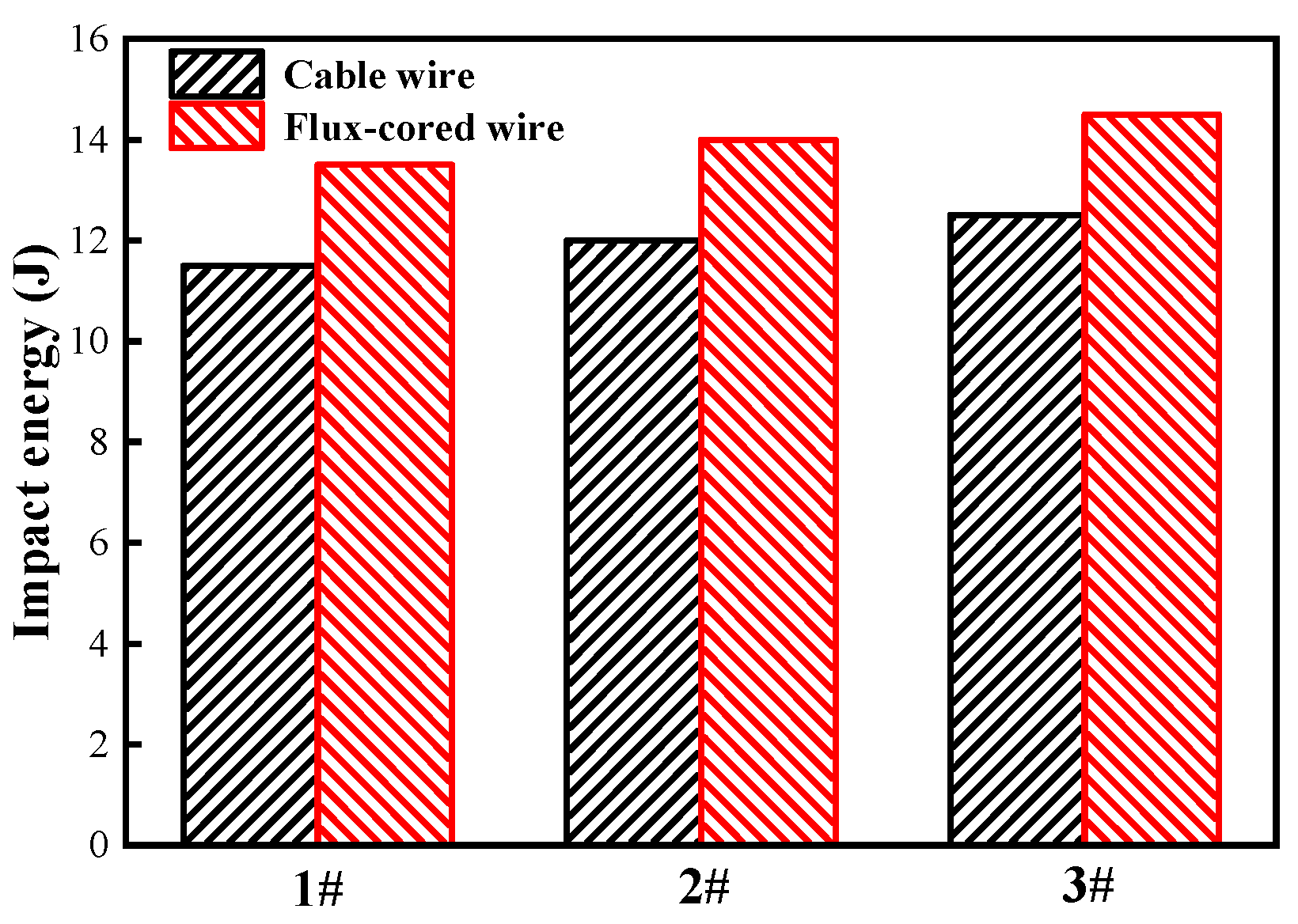
- The strength of the joints welded with flux-cored and cable wire is higher than that of the base metal. During the tensile tests, fractures occurred in the base metal region, indicating that the welded joints can meet the requirements of engineering applications. The impact energy of the flux-cored wire welded joint at room temperature is higher than that of the cable wire joint by 16.7%, and the fracture morphology shows toughness fracture.
- (3)
- As a filler material, flux-cored wire achieves better performance in terms of the microstructure and mechanical properties when using a laser to weld TC4 titanium alloy. This is mainly because the flux-cored structure transits the alloying elements into the molten pool in the form of multielement microalloying. It also plays a metallurgical role in enhancing the comprehensive performance and improving the coarse microstructure and anisotropy in welding thick-walled TC4 titanium alloy.
Author Contributions
Funding
Institutional Review Board Statement
Informed Consent Statement
Data Availability Statement
Conflicts of Interest
References
- Lütjering, G. Influence of processing on microstructure and mechanical properties of (α+β) titanium alloys. Mater. Sci. Eng. A 1998, 243, 32–45. [Google Scholar] [CrossRef]
- Wang, Z.; Sun, L.; Ke, W.; Zeng, Z.; Yao, W.; Wang, C. Laser Oscillating Welding of TC31 High-Temperature Titanium Alloy. Metals 2020, 10, 1185. [Google Scholar] [CrossRef]
- Kumar, M.R.; Jouvard, J.; Tomashchuk, I.; Sallamand, P. Vapor plume and melted zone behavior during dissimilar laser welding of titanium to aluminum alloy. Proc. Inst. Mech. Eng. Part L: J. Mater. Des. Appl. 2020, 234, 681–696. [Google Scholar]
- Cheepu, M.; Venkateswarlu, D.; Rao, P.N.; Kumaran, S.S.; Srinivasan, N. Optimization of Process Parameters Using Surface Response Methodology for Laser Welding of Titanium Alloy. Mater. Sci. Forum 2019, 969, 539–545. [Google Scholar] [CrossRef]
- Panwisawas, C.; Perumal, B.; Ward, R.M.; Turner, N.; Turner, R.P.; Brooks, J.W.; Basoalto, H.C. Keyhole formation and thermal fluid flow-induced porosity during laser fusion welding in titanium alloys: Experimental and modelling. Acta Mater. 2017, 126, 251–263. [Google Scholar] [CrossRef]
- Li, Q.F.; Wang, P.; Liu, D.; Wang, J.; Liu, H.J.; Wang, Y.B. Experimental Study on Fatigue Crack Growth in a Titanium Alloy. Key Eng. Mater. 2005, 297–300, 2489–2494. [Google Scholar] [CrossRef]
- Kalaiselvan, K.; Elango, A.; Nagarajan, N.M.; Sekar, K. Experimental Investigation on Mechanical and Distortion Characteristics of Titanium/Aluminium Dissimilar Metal Joint Using Laser Beam Welding. J. Adv. Manuf. Syst. 2018, 17, 569–579. [Google Scholar] [CrossRef]
- Akman, E.; Demir, A.; Canel, T.; Sınmazçelik, T. Laser welding of Ti6Al4V titanium alloys. J. Mater. Process. Technol. 2009, 209, 3705–3713. [Google Scholar] [CrossRef]
- Grebennikov, V.A.; Uglov, A.A.; Eremin, A.I. Embrittlement of welded joints produced by pulsed laser welding. Weld. Int. 1998, 12, 220–224. [Google Scholar] [CrossRef]
- Fang, N.; Guo, E.; Xu, K.; Huang, R.; Ma, Y.; Zeng, C.; Yang, Y.; Xie, J.; Cao, H. Effect of Shielding Gas on Microstructures and Mechanical Properties of TC4 Titanium Alloy Ultranarrow Gap Welded Joint by Laser Welding with Filler Wire. Adv. Mater. Sci. Eng. 2021, 2021, 9582421. [Google Scholar] [CrossRef]
- Fang, N.; Guo, E.; Huang, R.; Yin, L.; Chen, Y.; Zeng, C.; Cao, H.; Zou, J.; Xu, K. Effect of welding heat input on microstructure and properties of TC4 titanium alloy ultra-narrow gap welded joint by laser welding with filler wire. Mater. Res. Express 2021, 8, 016511. [Google Scholar] [CrossRef]
- Zhang, Y.; Chen, Y.; Zhou, J.; Sun, D.; Li, H. Experimental and numerical study on microstructure and mechanical properties for laser welding-brazing of TC4 Titanium alloy and 304 stainless steel with Cu-base filler metal. J. Mater. Res. Technol. 2020, 9, 465–477. [Google Scholar] [CrossRef]
- Sun, Q.; Li, J.; Liu, Y.; Jiang, Y.; Kang, K.; Feng, J. Arc characteristics and droplet transfer process in CMT welding with a magnetic field. J. Manuf. Process. 2018, 32, 48–56. [Google Scholar] [CrossRef]
- Yue, C.; Yin, A. Effect of transverse magnetic field on microstructure and mechanical properties of Ti-6Al-4 V manufactured by Laser-MIG hybrid welding. Int. J. Adv. Manuf. Technol. 2022, 121, 5283–5296. [Google Scholar] [CrossRef]
- Ma, T.J.; Li, X.; Zhong, B.; Li, W.Y. Effects of annealing on microstructure and properties of linear friction welded dissimilar titanium joints. Sci. Technol. Weld. Join. 2014, 19, 689–695. [Google Scholar] [CrossRef]
- Li, J.Z.; Liu, Y.B.; Zhen, Z.Y.; Jin, P.; Sun, Q.J.; Feng, J.C. Weld Formation Mechanism and Microstructural Evolution of TC4/304 stainless Steel Joint with Cu-Based Filler Wire and Preheating. Materials 2019, 12, 3071. [Google Scholar] [CrossRef]
- Xu, L.Y.; Zhu, J.; Jing, H.Y.; Zhao, L.; Lv, X.Q.; Han, Y.D. Effects of deep cryogenic treatment on the residual stress and mechanical properties of electron-beam-welded Ti-6Al-4V joints. Mater. Sci. Eng. A 2016, 673, 503–510. [Google Scholar] [CrossRef]
- Chen, C.; Fan, C.; Cai, X.; Lin, S.; Liu, Z.; Fan, Q.; Yang, C. Investigation of formation and microstructure of Ti-6Al-4V weld bead during pulse ultrasound assisted TIG welding. J. Manuf. Process. 2019, 46, 241–247. [Google Scholar] [CrossRef]
- Bajić, D.; Mrdak, M.; Bajić, N.; Veljić, D.; Rakin, M.; Radosavljević, Z. Development of Coated Electrodes with Solid Wire and Flux-Cored Alloyed Wire for Microalloyed Steel Welding. Materials 2020, 13, 2152. [Google Scholar] [CrossRef]
- Mukhopadhyay, S.; Pal, T. Effect of shielding gas mixture on gas metal arc welding of HSLA steel using solid and flux-cored wires. Int. J. Adv. Manuf. Technol. 2005, 29, 262–268. [Google Scholar] [CrossRef]
- Prilutsky, V.P.; Akhonin, S.V. TIG welding of titanium alloys using fluxes. Weld. World 2013, 58, 245–251. [Google Scholar] [CrossRef]
- Bao, Y.; Huang, L.; Jiang, S.; Zhang, R.; An, Q.; Zhang, C.; Geng, L.; Ma, X. A novel Ti cored wire developed for wire-feed arc deposition of TiB/Ti composite coating. J. Mater. Sci. Technol. 2021, 83, 145–160. [Google Scholar] [CrossRef]
- Chen, Y.; Fang, C.; Yang, Z.; Wang, J.; Wu, M.; Chen, S. A study on sidewall penetration of cable-type welding wire electrogas welding. Weld. World 2017, 61, 979–986. [Google Scholar] [CrossRef]
- Chen, Y.; Fang, C.; Yang, Z.; Wang, J.; Xu, G.; Gu, X. Cable-type welding wire arc welding. Int. J. Adv. Manuf. Technol. 2017, 94, 835–844. [Google Scholar] [CrossRef]
- Yang, Z.; Fang, C.; Wu, M.; Qi, K.; Chen, Y.; Ma, R. The mechanisms of arc coupling and rotation in cable-type welding wire CO2 welding. J. Mater. Process. Technol. 2018, 255, 443–450. [Google Scholar] [CrossRef]
- Yang, Z.; Chen, Y.; Zhang, Z.; Fang, C.; Xu, K.; He, P.; Zhang, Z. Research on the sidewall penetration mechanisms of cable-type welding wire narrow gap GMAW process. Int. J. Adv. Manuf. Technol. 2022, 120, 2443–2455. [Google Scholar] [CrossRef]
- Li, J.; Li, H.; Liang, Y.; Liu, P.; Yang, L. The Microstructure and Mechanical Properties of Multi-Strand, Composite Welding-Wire Welded Joints of High Nitrogen Austenitic Stainless Steel. Materials 2019, 12, 2944. [Google Scholar] [CrossRef]
- Lei, Z.; Dong, Z.; Chen, Y.; Huang, L.; Zhu, R. Microstructure and mechanical properties of laser welded Ti–22Al–27Nb/TC4 dissimilar alloys. Mater. Sci. Eng. A 2013, 559, 909–916. [Google Scholar] [CrossRef]
- Lu, W.; Shi, Y.; Lei, Y.; Li, X. Effect of electron beam welding on the microstructures and mechanical properties of thick TC4-DT alloy. Mater. Des. 2012, 34, 509–515. [Google Scholar] [CrossRef]
- Auwal, S.T.; Ramesh, S.; Yusof, F.; Manladan, S.M. A review on laser beam welding of titanium alloys. Int. J. Adv. Manuf. Technol. 2018, 97, 1071–1098. [Google Scholar] [CrossRef]
- Shi, J.; Song, G.; Chi, J. Effect of active gas on weld appearance and performance in laser-TIG hybrid welded titanium alloy. Int. J. Light. Mater. Manuf. 2018, 1, 47–53. [Google Scholar] [CrossRef]
- Li, X.; Hu, S.; Xiao, J.; Ji, L. Effects of the heterogeneity in the electron beam welded joint on fatigue crack growth in Ti–6Al–4V alloy. Mater. Sci. Eng. A 2011, 529, 170–176. [Google Scholar] [CrossRef]
- Fang, C.F.; Chen, Y.; Yang, Z.D.; Wang, J.Y.; Wu, M.F.; Qi, K. Cable-type welding wire submerged arc surfacing. J. Mater. Process. Tech. 2017, 249, 25–31. [Google Scholar] [CrossRef]
- Li, C.; Chen, J.; Li, W.; He, J.; Qiu, W.; Ren, Y. Study on the relationship between microstructure and mechanical property in a metastable β titanium alloy. J. Alloy. Compd. 2014, 627, 222–230. [Google Scholar] [CrossRef]
- Winco, K.C.; Yung, B.R.; Leec, W.B.; Fenn, R. An investigation into welding parameters affecting the tensile properties of titanium welds. J. Mater. Process. Technol. 1997, 63, 759–764. [Google Scholar]
- Balasubramanian, T.S.; Balakrishnan, M.; Balasubramanian, V.; Muthu Manickam, M.A. Effect of welding processes on joint characteristics of Ti-6Al-4V alloy. Sci. Technol. Weld. Join. 2011, 16, 702–708. [Google Scholar] [CrossRef]
- Zeng, L.; Bieler, T.R. Effects of working, heat treatment, and aging on microstructural evolution and crystallographic texture of a, a’, a” and β phases in Ti-6Al-4V wire. Mater. Sci. Eng. A 2005, 392, 403–414. [Google Scholar] [CrossRef]
- Ma, Q.; Li, H.L.; Liu, S.X.; Liu, D.; Wang, P.F.; Zhu, Q.; Lei, Y.C. Comparative Evaluation of Self-Shielded Flux-Cored Wires Designed for High Strength Low Alloy Steel in Underwater Wet Welding: Arc Stability, Slag Characteristics, and Joints Quality. J. Mater. Eng. Perform. 2022, 31, 5231–5244. [Google Scholar] [CrossRef]
- Zhou, Y.F.; Yang, Y.L.; Yang, J.; Hao, F.F.; Li, D.; Ren, X.J.; Yang, Q.X. Effect of Ti additive on (Cr, Fe)(7)C-3 carbide in arc surfacing layer and its refined mechanism. Appl. Surf. Sci. 2012, 258, 6653–6659. [Google Scholar] [CrossRef]
- Holly, S.; Mayer, P.; Bernhard, C.; Posch, G. Slag characterisation of 308L-type stainless steel rutile flux-cored wires. Weld. World. 2019, 63, 293–311. [Google Scholar] [CrossRef]
- Chen, Y.; Sun, X.S.; Zhang, T.; Li, Q.T.; Ni, S.Y.; Fang, C.F. Arc rotating behavior of SRA EGW in AH36 steel. Mater. Manuf. Process. 2020, 35, 556–563. [Google Scholar] [CrossRef]


| Material | Al | V | Fe | C | N | H | O | Ti |
|---|---|---|---|---|---|---|---|---|
| Base material | 6.30 | 4.11 | 0.018 | 0.024 | 0.007 | 0.001 | 0.14 | Balance |
| Flux-cored wire | 6.10 | 4.15 | 0.040 | 0.012 | 0.006 | 0.001 | 0.02 | Balance |
| Cable wire | 6.20 | 3.92 | 0.020 | 0.028 | 0.005 | 0.001 | 0.10 | Balance |
| Process Parameter | Flux-Cored Wire Welding | Cable Wire Welding |
|---|---|---|
| Laser power (W) | 3000 | 4000 |
| Welding speed (mm/min) | 0.65 | 0.42 |
| Wire feeding rate (mm/min) | 1.5 | 3.5 |
| Defocusing distance (mm) | 20 | 20 |
| Oscillation pattern | Circle | Circle |
| Oscillation frequency (Hz) | 100 | 100 |
| Oscillation diameter (mm) | 2 | 2 |
| Shielding gas | Ar | Ar |
| Gas flow rate (L/min) | 35 | 35 |
| Mechanical Property | Flux-Cored Wire Welding | Cable Wire Welding |
|---|---|---|
| Tensile strength (MPa) | 925 | 941 |
| Elongation (%) | 12.5 | 11 |
| Fracture location for tension | BM | BM |
| Charpy impact energy (J) | 14 | 12 |
Disclaimer/Publisher’s Note: The statements, opinions and data contained in all publications are solely those of the individual author(s) and contributor(s) and not of MDPI and/or the editor(s). MDPI and/or the editor(s) disclaim responsibility for any injury to people or property resulting from any ideas, methods, instructions or products referred to in the content. |
© 2023 by the authors. Licensee MDPI, Basel, Switzerland. This article is an open access article distributed under the terms and conditions of the Creative Commons Attribution (CC BY) license (https://creativecommons.org/licenses/by/4.0/).
Share and Cite
Sun, L.; Wang, M.; Huang, L.; Fang, N.; Wu, P.; Huang, R.; Xu, K.; Wang, X.; Qin, J.; Li, S.; et al. Comparative Study on Laser Welding Thick-Walled TC4 Titanium Alloy with Flux-Cored Wire and Cable Wire. Materials 2023, 16, 1509. https://doi.org/10.3390/ma16041509
Sun L, Wang M, Huang L, Fang N, Wu P, Huang R, Xu K, Wang X, Qin J, Li S, et al. Comparative Study on Laser Welding Thick-Walled TC4 Titanium Alloy with Flux-Cored Wire and Cable Wire. Materials. 2023; 16(4):1509. https://doi.org/10.3390/ma16041509
Chicago/Turabian StyleSun, Laibo, Mingqiu Wang, Lujun Huang, Naiwen Fang, Pengbo Wu, Ruisheng Huang, Kai Xu, Xingxing Wang, Jian Qin, Shuai Li, and et al. 2023. "Comparative Study on Laser Welding Thick-Walled TC4 Titanium Alloy with Flux-Cored Wire and Cable Wire" Materials 16, no. 4: 1509. https://doi.org/10.3390/ma16041509
APA StyleSun, L., Wang, M., Huang, L., Fang, N., Wu, P., Huang, R., Xu, K., Wang, X., Qin, J., Li, S., & Long, W. (2023). Comparative Study on Laser Welding Thick-Walled TC4 Titanium Alloy with Flux-Cored Wire and Cable Wire. Materials, 16(4), 1509. https://doi.org/10.3390/ma16041509