Failure Mechanism of Fiber-Reinforced Prestressed Concrete Containments under Internal Pressure Considering Different Fiber Types

Abstract
:1. Introduction
2. Finite Element Model
2.1. The Geometry of the Containment
2.2. Analytical Model and Finite Element Mesh
2.3. Material Properties and Constitution
2.3.1. Plain Concrete
2.3.2. Modeling of FRC
2.3.3. The Material Property Parameters of Steel
3. The Failure Mechanism Analysis for the Conventional PCCV
3.1. Deformation Response for the Conventional Containment
3.2. Pressure Performance of the Steel Liner
3.3. Pressure Performance of Prestressing Tendons
3.4. Evolution Rule of Cracks and Principal Tensile Strain in Concrete
4. The Failure Analysis for the FRC Containment under Internal Pressure
4.1. Deformation Response and Failure Modes for the Fiber-Reinforced PCCV
4.2. Pressure Performance of Steel Liner
4.3. Pressure Performance of Prestressing Tendons
4.4. Evolution Rule of Cracks and Principal Tensile Strain in Concrete
4.5. Analysis of the Failure Mechanism
5. Conclusions
- The failure mechanism for the fiber-reinforced containment is different from that of the containment without fiber reinforcement. Due to the higher peak tensile strength of the FRC, the crack occurrence time can be effectively retarded, and thus, the crack-resistant capacity of the structure can be increased. As for the FRC having greater post-peak tensile strength, the speed of the yielding evolution of the steel liner is effectively delayed, and thus, the functional failure capacity provided by the steel liner can be enhanced. Meanwhile, larger post-peak tensile strength can result in evident enhancement of the ultimate internal pressure capacity and smaller failure regions for prestressing tendons under internal pressure. It is demonstrated that the failure regions can be controlled under the ultimate internal pressure via the appropriate use of FRC.
- The results of crack evolution show that adding different fibers into concrete can effectively delay the occurrence of concrete cracks and inhibit the development speed of cracks to varying degrees. The internal pressure of the structure to resist concrete cracks is increased within that interval [14.9%, 28.0%], with the steel fiber achieving the largest contribution of 28%.
- The yielding pressure of the steel liner can be elevated by 11.3%, 9.0%, and 7.3% for steel-, steel-PP-, and steel-PVA-reinforcement, respectively. It is very beneficial to reduce the possibility of leakage occurrence in case of emergency through using these three types of fiber reinforcement. At the stage of ultimate pressure, the steel lining becomes plastic in the head and at the bottom of the equipment hatch, and plasticity regions tend to develop around the equipment hatch hole.
- The ultimate bearing capacity of the structure can be increased by about 12.5%, 10.3%, and 10.4%, respectively, with the addition of steel, steel-PP, and steel-PVA. As mentioned above, it is recommended that steel, steel-PP, and steel-PVA reinforcement be considered, as ultimate pressure capacity is the primary goal. However, due to the complex service environments of the containment, the mechanical properties of the steel fiber may be corroded in service and the long-term performance of the containment can thus be greatly degraded. In this case, the hybrid fiber in terms of steel-PP and steel-PVA may be a better alternative and needs further investigation.
Author Contributions
Funding
Institutional Review Board Statement
Informed Consent Statement
Data Availability Statement
Conflicts of Interest
References
- Taira, T.; Sasaki, Y.; Shibata, H.; Sato, H.; Kubo, T.; Kawakami, S.; Ohno, T.; Karasawa, Y. Large scale seismic proving test of BMR reactor pressure vessel by Tadotsu table. In Proceedings of the Transactions of the 11th SMiRT Conference, Berlin, Germany, 18–23 August 1991. [Google Scholar]
- Nakamura, S.; Sasaki, Y.; Horibe, K.; Nakajima, M.; Hoshino, K.; Takahashi, T.; Hagesawa, T.; Kei, T.; Meida, T.; Takigushi, K.; et al. Plan of the seismic proving test for reinforced concrete containment vessel (part1: Test model and test model design). In Proceedings of the Transactions of the 14th SMiRT Conference, Lyon, France, 17–22 August 1997. [Google Scholar]
- Nakamura, S.; Terada, K.; Suzuki, T.; Soejima, M.; Yamaura, Y.; Eto, H.; Nagahara, K.; Takigushi, K.; Akiyama, H. Seismic proving test of concrete containment vessels (part1: Model tests of a curved shear wall for the PCCV). In Proceedings of the Transactions of the 11th WCEE Conference, Acapulco, Mexico, 23–28 June 1996. [Google Scholar]
- Hirama, T.; Goto, M.; Hasegawa, T.; Kanechika, M.; Kei, T.; Mieda, T.; Abe, H.; Takiguchi, K.; Akiyama, H. Seismic proof test of a reinforced concrete containment vessel (RCCV) Part 1: Test model and pressure test. Nucl. Eng. Des. 2005, 235, 1335–1348. [Google Scholar] [CrossRef]
- Hirama, T.; Goto, M.; Shiba, K.; Kobayashi, T.; Tanaka, R.; Tsurumaki, S.; Takiguchi, K.; Akiyama, H. Seismic proof test of a reinforced concrete containment vessel (RCCV) Part 2: Results of shaking table tests. Nucl. Eng. Des. 2005, 235, 1349–1371. [Google Scholar]
- Hirama, T.; Goto, M.; Kumagai, H.; Naito, Y.; Suzuki, A.; Abe, H.; Takiguchi, K.; Akiyama, H. Seismic proof test of a reinforced concrete containment vessel (RCCV) Part 3. Evaluation of seismic safety margin. Nucl. Eng. Des. 2007, 237, 1128–1139. [Google Scholar]
- Dameron, R.A.; Rashid, Y.R.; Hessheimer, M.F. Posttest analysis of a 1:4-scale prestressed concrete containment vessel model. In Proceedings of the Transactions of the 17th SMiRT Conference, Prague, Czech Republic, 17–22 August 2003. [Google Scholar]
- Hessheimer, M.F.; Shibata, S.; Costello, J.F. Functional and structural failure mode overpressurization tests of 1:4-scale prestressed concrete containment vessel model. In Proceedings of the Transactions of the 17th SMiRT Conference, Prague, Czech Republic, 17–22 August 2003. [Google Scholar]
- Parmar, R.M.; Singh, T.; Thangamani, I.; Trivedi, N.; Singh, R.K. Over-pressure test on BARCOM pre-stressed concrete containment. Nucl. Eng. Des. 2014, 269, 177–183. [Google Scholar] [CrossRef]
- Hu, H.T.; Liang, J.L. Ultimate analysis of BWR Mark III reinforced concrete containment subjected to internal pressure. Nucl. Eng. Des. 2000, 195, 1–11. [Google Scholar] [CrossRef]
- Kenji, Y.; Katsuyoshi, I.; Yukio, W.; Masahito, A. Ultimate capacity analysis of 1/4 PCCV model subjected to internal pressure. Nucl. Eng. Des. 2002, 212, 357–379. [Google Scholar]
- Ghavamian, S.; Courtois, A.; Valfort, J.L. Mechanical simulations of SANDIA II tests OECD ISP 48 benchmark. In Proceedings of the Transactions of the 18th SMiRT Conference, Beijing, China, 7–12 August 2005. [Google Scholar]
- Kwak, H.G.; Kim, J.H. Numerical models for prestressing tendons in containment structures. Nucl. Eng. Des. 2006, 236, 1061–1080. [Google Scholar]
- Patrick, A. Analytic study of the steel liner near the equipment hatch in a 1:4 scale containment model. Nucl. Eng. Des. 2008, 238, 1641–1650. [Google Scholar]
- Zhang, C.; Chen, J.; Li, J. Ultimate internal pressure of prestressed concrete containment vessel analyzed by an integral constitutive model. KSCE J. Civ. Eng. 2016, 21, 2273–2280. [Google Scholar]
- Yan, J.C.; Lin, Y.Z.; Wang, Z.F.; Fang, T.; Ma, J.L. Failure mechanism of a prestressed concrete containment vessel in nuclear power plant subjected to accident internal pressure. Ann. Nucl. Energy 2019, 133, 610–622. [Google Scholar]
- Holschemacher, K.; Mueller, T.; Ribakov, Y. Effect of steel fibres on mechanical properties of high-strength concrete. Mater. Des. 2010, 31, 2604–2615. [Google Scholar] [CrossRef]
- Mukherjee, A.; Joshi, M. FRPC reinforced concrete beam-column joints under cyclic excitation. Comp. Struct. 2005, 70, 185–199. [Google Scholar] [CrossRef]
- Mohammed, H.; Ahmed, H.; Kurda, R.; Alyousef, R.; Deifalla, A.F. Heat-Induced Spalling of Concrete: A Review of the Influencing Factors and Their Importance to the Phenomenon. Materials 2022, 15, 1693. [Google Scholar] [CrossRef]
- Irshidat, M.R.; Al-Nuaimi, N.; Rabie, M. The Role of Polypropylene Microfibers in Thermal Properties and Post-Heating Behavior of Cementitious Composites. Materials 2020, 13, 2676. [Google Scholar] [CrossRef]
- Cho, C.G.; Kim, Y.Y.; Feo, L.; Hui, D. Cyclic responses of reinforced concrete composite columns strengthened in the plastic hinge region by HPFRC mortar. Compos. Struct. 2012, 94, 2246–2253. [Google Scholar]
- Xie, J.; Hu, R. Experimental study on rehabilitation of corrosion-damaged reinforced concrete beams with carbon fiber reinforced polymer. Constr. Build. Mater. 2013, 38, 708–716. [Google Scholar]
- Triantafyllou, G.G.; Rousakis, T.C.; Karabinis, A.I. Corroded RC beams patch repaired and strengthened in flexure with fiber-reinforced polymer laminates. Compos. Part B-Eng. 2017, 112, 125–136. [Google Scholar]
- Shah, S.P.; Rangan, B.V. Fiber reinforced concrete properties. ACI J. 1971, 68, 126–135. [Google Scholar]
- Abrishami, H.H.; Mitchell, D. Influence of steel fibers on tension stiffening. ACI Struct. J. 1997, 94, 769–775. [Google Scholar]
- Bischoff, P.H. Tension stiffening and cracking of steel fiber reinforced concrete. J. Mater. Civ. Eng. 2003, 15, 174–182. [Google Scholar]
- Deluce, J.R.; Vecchio, F.J. Cracking behavior of steel fiber reinforced concrete members containing conventional reinforcement. ACI Struct. J. 2013, 110, 481–490. [Google Scholar]
- Choun, Y.S.; Park, H.K. Containment performance evaluation of prestressed concrete containment vessels with fiber reinforcement. Nucl. Eng. Technol. 2015, 47, 884–894. [Google Scholar] [CrossRef]
- Lubliner, J.; Oliver, J.; Oller, S.; Oñate, E. A plastic-damage model for concrete. Int. J. Solids Struct. 1989, 25, 299–326. [Google Scholar]
- GB50010-2002; Code for Design of Concrete Structures. The Ministry of Construction of the People’s Republic of China, MOC: Beijing, China, 2002.
- Sidorof, F. Description of anisotropic damage application to elasticity. In Proceedings of the IUTAM Symposium on Physical Nonlinearites in Structural Analysis, Senlis, France, 27–30 May 1980; Springer: Berlin/Heidelberg, Germany, 1981. [Google Scholar]
- ABAQUS. ABAQUS Standard User’s Manual, Version 6.14; Dassault Systemes Corp: Providence, RI, USA, 2012. [Google Scholar]
- Zhou, H.; Jia, B.; Huang, H.; Mou, Y. Experimental Study on Basic Mechanical Properties of Basalt Fiber Reinforced Concrete. Materials 2020, 13, 1362. [Google Scholar] [CrossRef]
- Shi, J.N.; Zhao, Y.R.; Hao, S.; Wang, L. Analysis of Uniaxial Compressive Stress-Strain Curves of Basalt Fiber Reinforced Concrete by DIC Technique. Bull. Chin. Ceram. Soc. 2019, 38, 1668–1673. [Google Scholar]
- Yu, L.; Cheng, H.; Jin, Y.X.; Wang, Y. Study on Uniaxial Compression Stress-strain Constitutive Relation of Carbon Fiber Reinforced Concrete. J. Logist. Eng. Univ. 2013, 29, 6–12. [Google Scholar]
- Li, J.H.; Deng, Z.C. Uniaxial tensile properties of carbon fiber reinforced concrete. Highway 2011, 000, 185–187. [Google Scholar]
- Deng, Z.C.; Li, J.H.; Fu, Z. The Uniaxial Tension Test of Polypropylene Fiber Reinforced Concrete. J. Highw. Transp. Res. Dev. 2005, 22, 45–48. [Google Scholar]
- Xu, L.H.; Huang, B.; Li, B.; Chi, Y.; Li, C.N.; Shi, Y.C. Study on the stress-strain relation of polypropylene fiber reinforced concrete under cyclic compression. China Civ. Eng. J. 2019, 52, 1–12. [Google Scholar]
- Gao, D.Y. Study on Uniaxial Tension Stress-strain Relation of Steel Fiber Reinforced Concrete. Water Power 1991, 11, 54–58. [Google Scholar]
- Gao, D.Y. Study on Uniaxial Compression Stress-strain Relation of Steel Fiber Reinforced Concrete. J. Hydraul. Eng. 1991, 10, 43–48. [Google Scholar]
- Chi, Y.; Xu, L.H.; Zhang, Y.Y. Experimental Study on Hybrid Fiber–Reinforced Concrete Subjected to Uniaxial Compression. J. Mater. Civ. Eng. 2014, 26, 211–218. [Google Scholar]
- Xu, L.H.; Mei, G.D.; Huang, L.; Lu, W. Study on uniaxial tensile stress-strain relationship of steel-polypropylene hybrid fiber reinforced concrete. China Civ. Eng. J. 2014, 47, 35–45. [Google Scholar]
- Zhong, G.C.; Zhou, Y.; Xiao, Y. Stress-strain behavior of steel-polyvinyl alcohol hybrid fiber reinforced concrete under axial compression and tension. Eng. Mech. 2020, 37, 111–120. [Google Scholar]
- Yang, Q.; Zhou, W.Y.; Chen, X. Thermodynamic Significance and Basis of Damage Variables and Equivalences. Int. J. Damage Mech. 2010, 19, 898–910. [Google Scholar] [CrossRef]
- GB50017-2017; Standard for Design of Steel Structures. The Ministry of Construction of the People’s Republic of China, MOC: Beijing, China, 2017.


| Index | Value |
|---|---|
| Density (kg/m3) | 2500 |
| Poisson’s ratio | 0.2 |
| Elastic modulus E0 (×104 MPa) | 3.45 |
| Peak intensity—compressive (MPa) | 32.4 |
| Peak intensity—tensile (MPa) | 2.64 |
| Dilation Angle () | Eccentricity (e) | Viscosity Parameter | ||
|---|---|---|---|---|
| 36° | 0.1 | 1.16 | 0.667 | 0.005 |
| Fiber Type | Density (kg/m3) | Elastic Modulus (GPa) | Tensile Strength (MPa) | Length/Diameter | Volume Fraction (%) | |||||
|---|---|---|---|---|---|---|---|---|---|---|
| Basalt | 2750 | 105 | 4256 | 1000 | 0.2 | |||||
| Carbon | 1780 | 238 | 3900 | 1000 | 0.1 | |||||
| PP | 910 | 6.5 | >400 | 396 | 0.14 | |||||
| Steel | 7800 | 200 | 1345 | 60 | 2 | |||||
| Steel-PP | 7800 (Steel) | 910 (PP) | 200 (Steel) | >3.5 (PP) | 1225 (Steel) | >400 (PP) | 60 (Steel) | 167 (PP) | 1.5 (Steel) | 0.15 (PP) |
| Steel-PVA | 7800 (Steel) | 1300 (PVA) | 200 (Steel) | 41 (PVA) | 1225 (Steel) | 1560 (PVA) | 65 (Steel) | 300 (PVA) | 1.3 (Steel) | 0.2 (PVA) |
| Type | Density (kg/m3) | Poisson’s Ratio | Elastic Modulus E0 (GPa) | Yield Strength fyk (MPa) | Ultimate Strength fptk (MPa) |
|---|---|---|---|---|---|
| Prestressing tendons | 7850 | 0.3 | 200 | / | 1860 |
| Reinforcing steel | 7800 | 0.3 | 195 | 400 | / |
| Steel liner | 7800 | 0.3 | 200 | 320 | / |
| Containment | Concrete Cracking (MPa) | Steel Liner Yielding (MPa) | Ultimate Internal Pressure (MPa) |
|---|---|---|---|
| Conventional | 0.585 | 0.950 | 1.643 |
| Basalt fiber | 0.674 | 0.964 | 1.659 |
| Carbon fiber | 0.677 | 0.960 | 1.661 |
| PP fiber | 0.702 | 0.963 | 1.626 |
| Steel fiber | 0.749 | 1.057 | 1.848 |
| Steel-PP fiber | 0.718 | 1.036 | 1.812 |
| Steel-PVA fiber | 0.672 | 1.019 | 1.814 |
| Fiber Types | dt | 0.8 MPa | 1.1 MPa | 1.4 MPa | Ultimate Pressure |
|---|---|---|---|---|---|
| Basalt fiber |  |  |  |  |  |
| Carbon fiber | 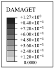 |  |  |  |  |
| PP fiber | 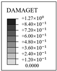 |  |  | 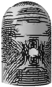 |  |
| Steel fiber |  |  |  |  | 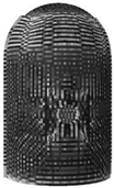 |
| Steel-PP fiber |  |  |  |  |  |
| Steel-PVA fiber |  |  |  |  |  |
Disclaimer/Publisher’s Note: The statements, opinions and data contained in all publications are solely those of the individual author(s) and contributor(s) and not of MDPI and/or the editor(s). MDPI and/or the editor(s) disclaim responsibility for any injury to people or property resulting from any ideas, methods, instructions or products referred to in the content. |
© 2023 by the authors. Licensee MDPI, Basel, Switzerland. This article is an open access article distributed under the terms and conditions of the Creative Commons Attribution (CC BY) license (https://creativecommons.org/licenses/by/4.0/).
Share and Cite
Zheng, Z.; Sun, Y.; Pan, X.; Zhang, L. Failure Mechanism of Fiber-Reinforced Prestressed Concrete Containments under Internal Pressure Considering Different Fiber Types. Materials 2023, 16, 1463. https://doi.org/10.3390/ma16041463
Zheng Z, Sun Y, Pan X, Zhang L. Failure Mechanism of Fiber-Reinforced Prestressed Concrete Containments under Internal Pressure Considering Different Fiber Types. Materials. 2023; 16(4):1463. https://doi.org/10.3390/ma16041463
Chicago/Turabian StyleZheng, Zhi, Ye Sun, Xiaolan Pan, and Lianpeng Zhang. 2023. "Failure Mechanism of Fiber-Reinforced Prestressed Concrete Containments under Internal Pressure Considering Different Fiber Types" Materials 16, no. 4: 1463. https://doi.org/10.3390/ma16041463
APA StyleZheng, Z., Sun, Y., Pan, X., & Zhang, L. (2023). Failure Mechanism of Fiber-Reinforced Prestressed Concrete Containments under Internal Pressure Considering Different Fiber Types. Materials, 16(4), 1463. https://doi.org/10.3390/ma16041463