

Coupled Modal Analysis and Aerodynamics of Rotating Composite Beam


Abstract
:1. Introduction
2. Dynamic Response of Composite Structure
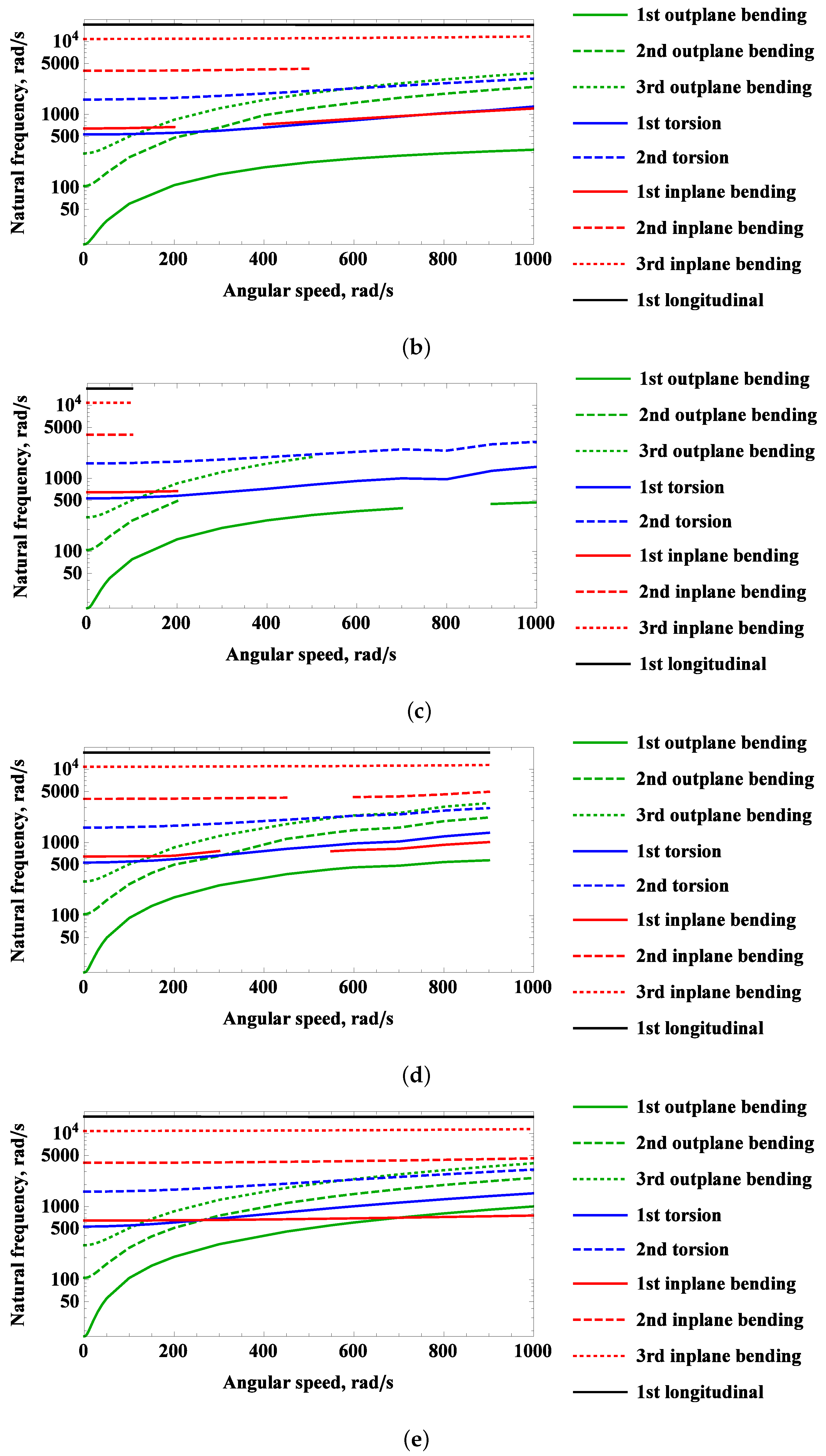
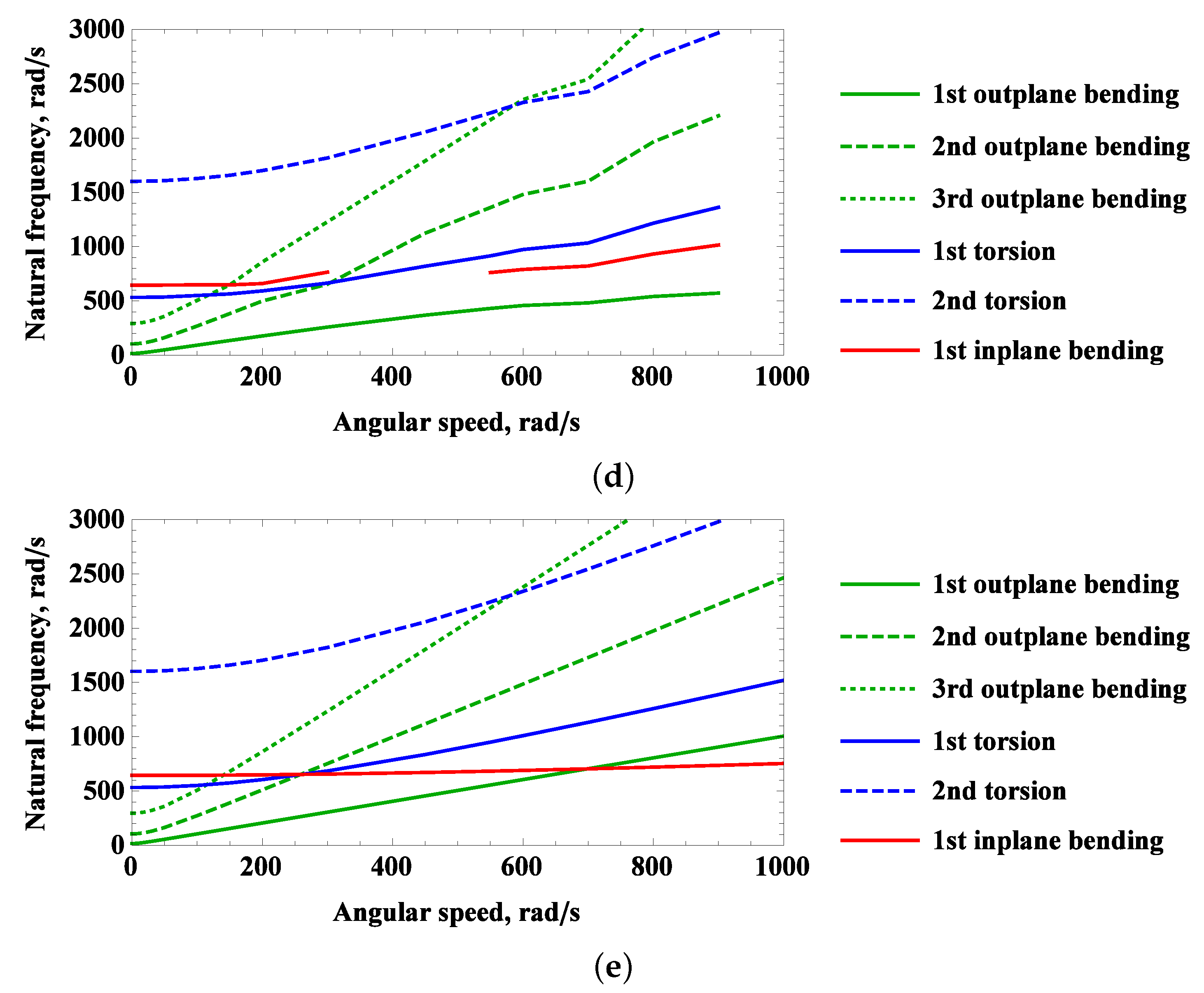
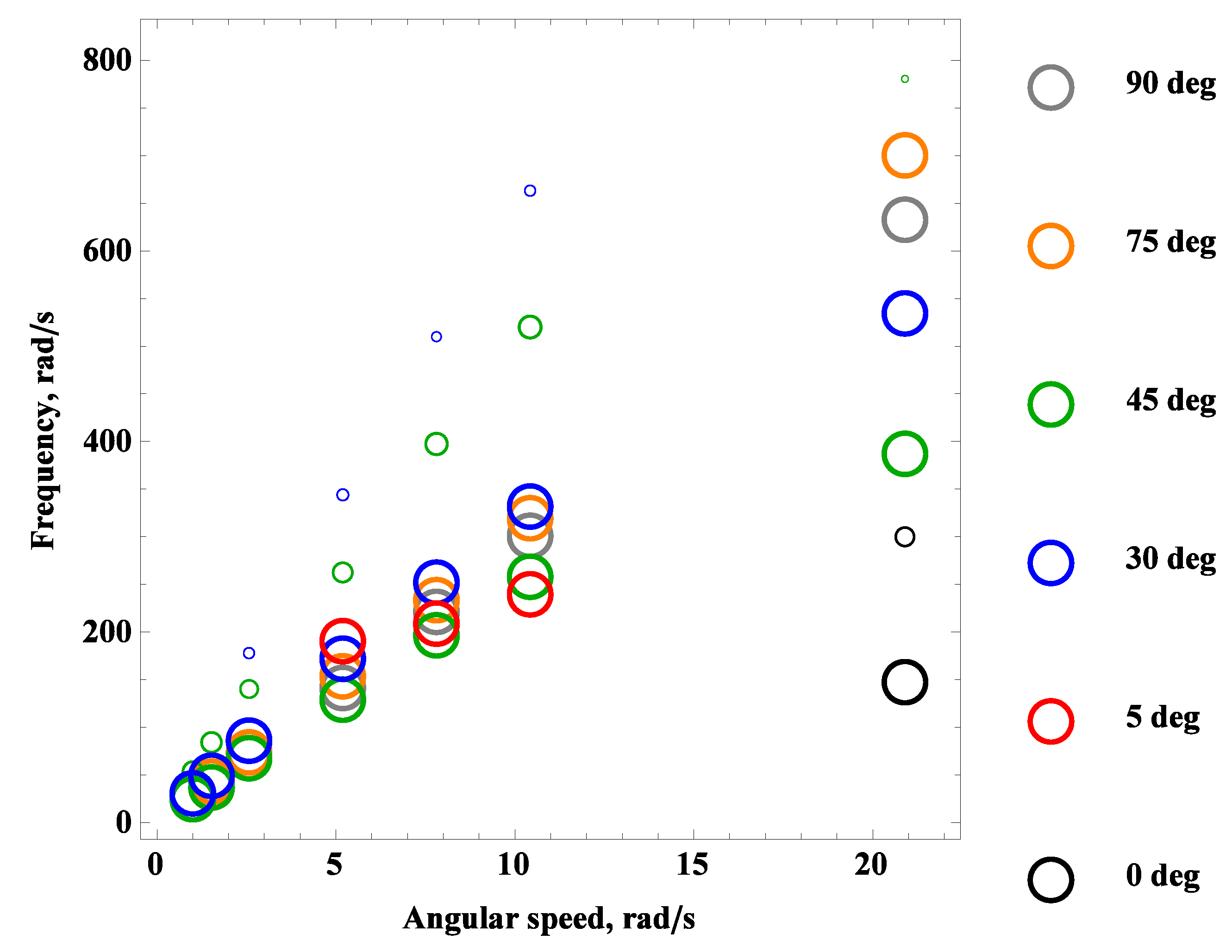
2.1. Campbell Diagram
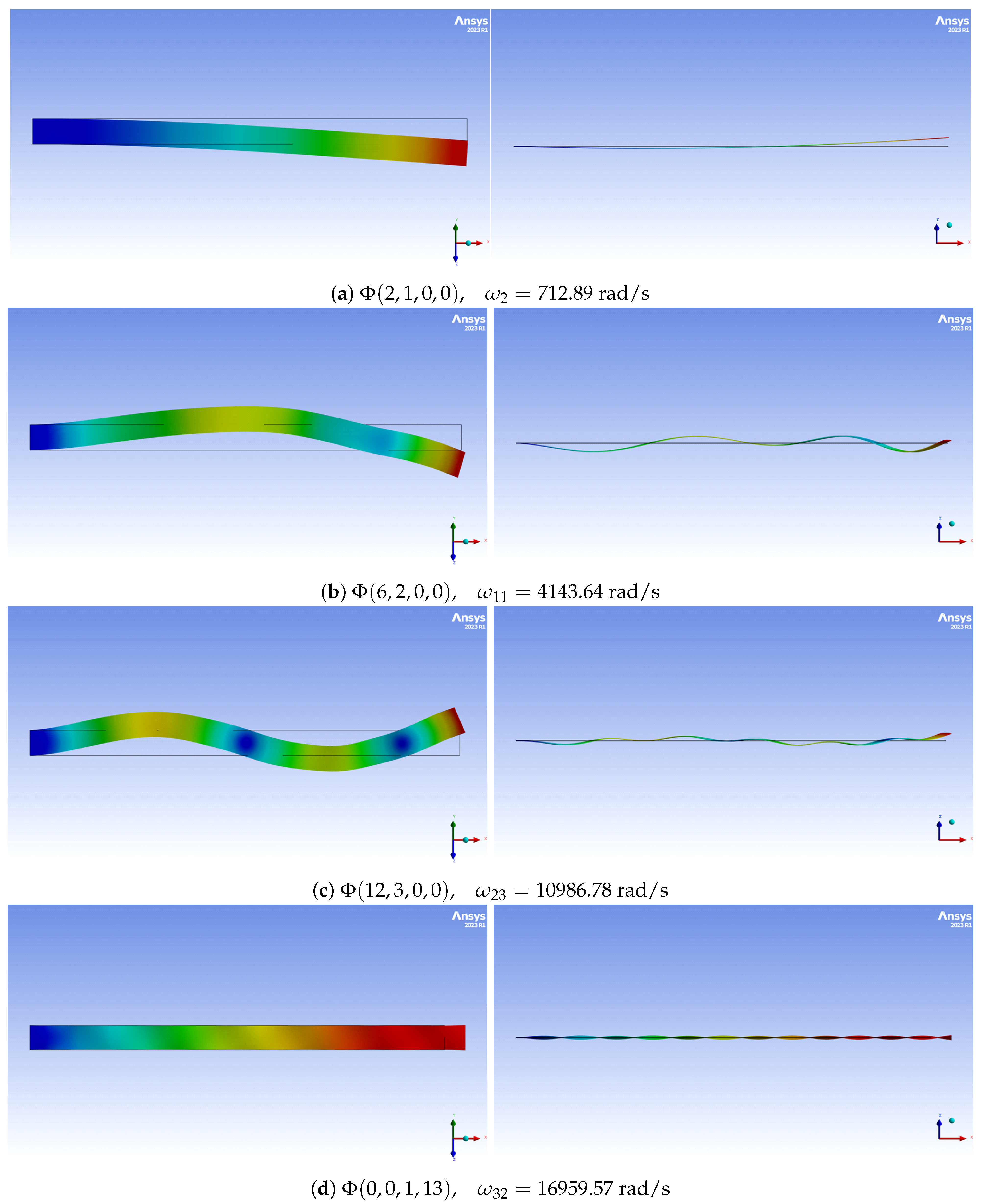
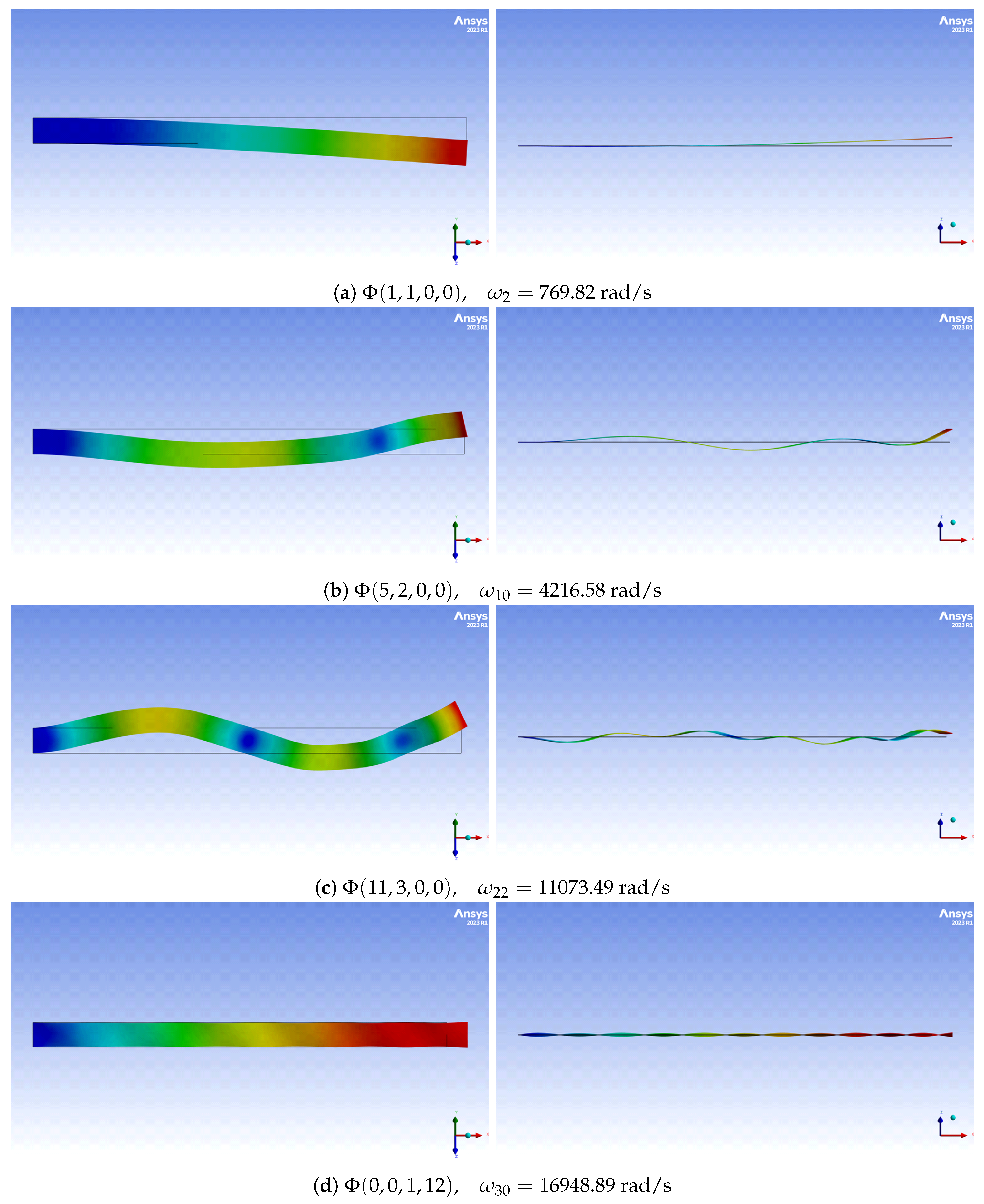
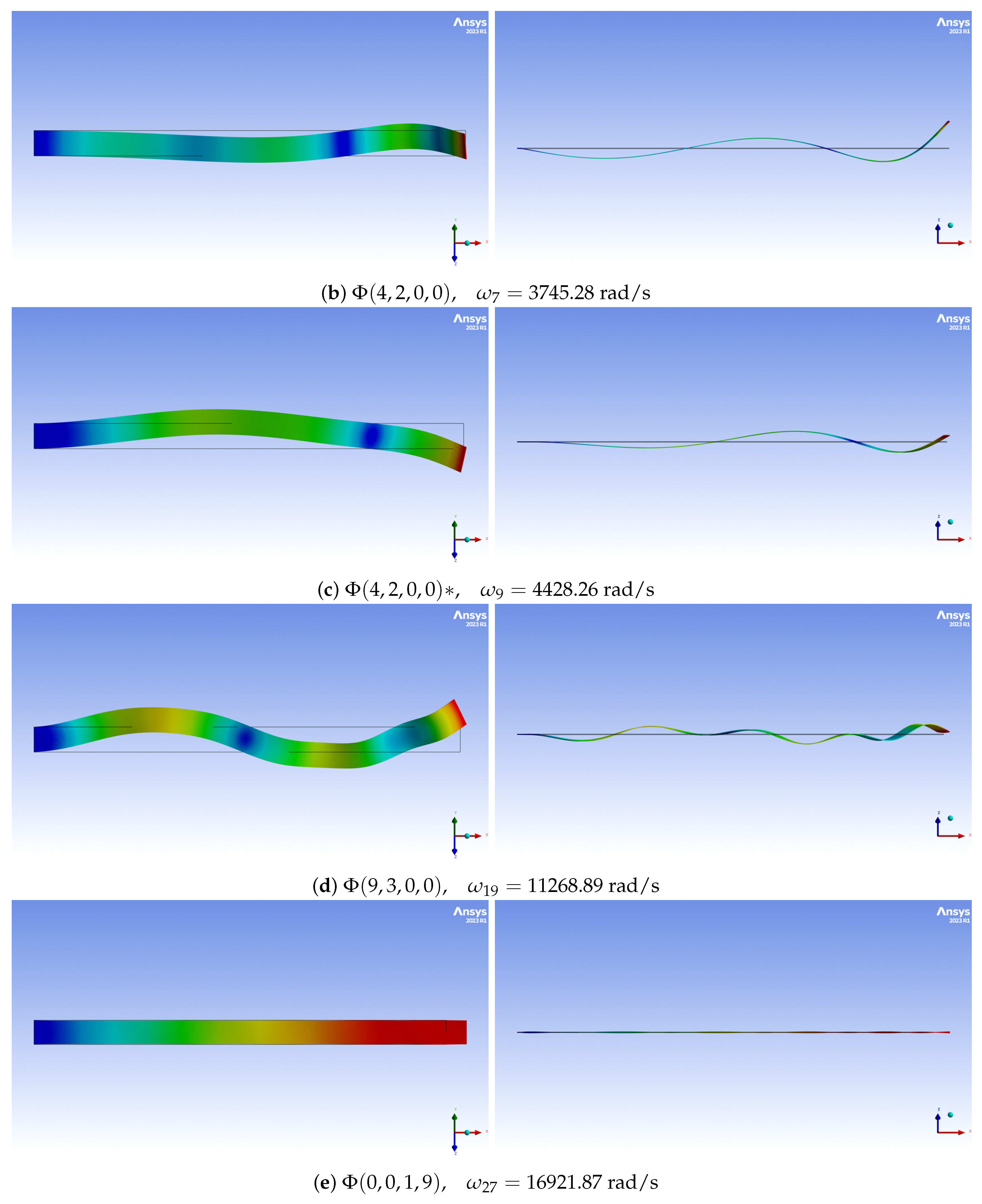
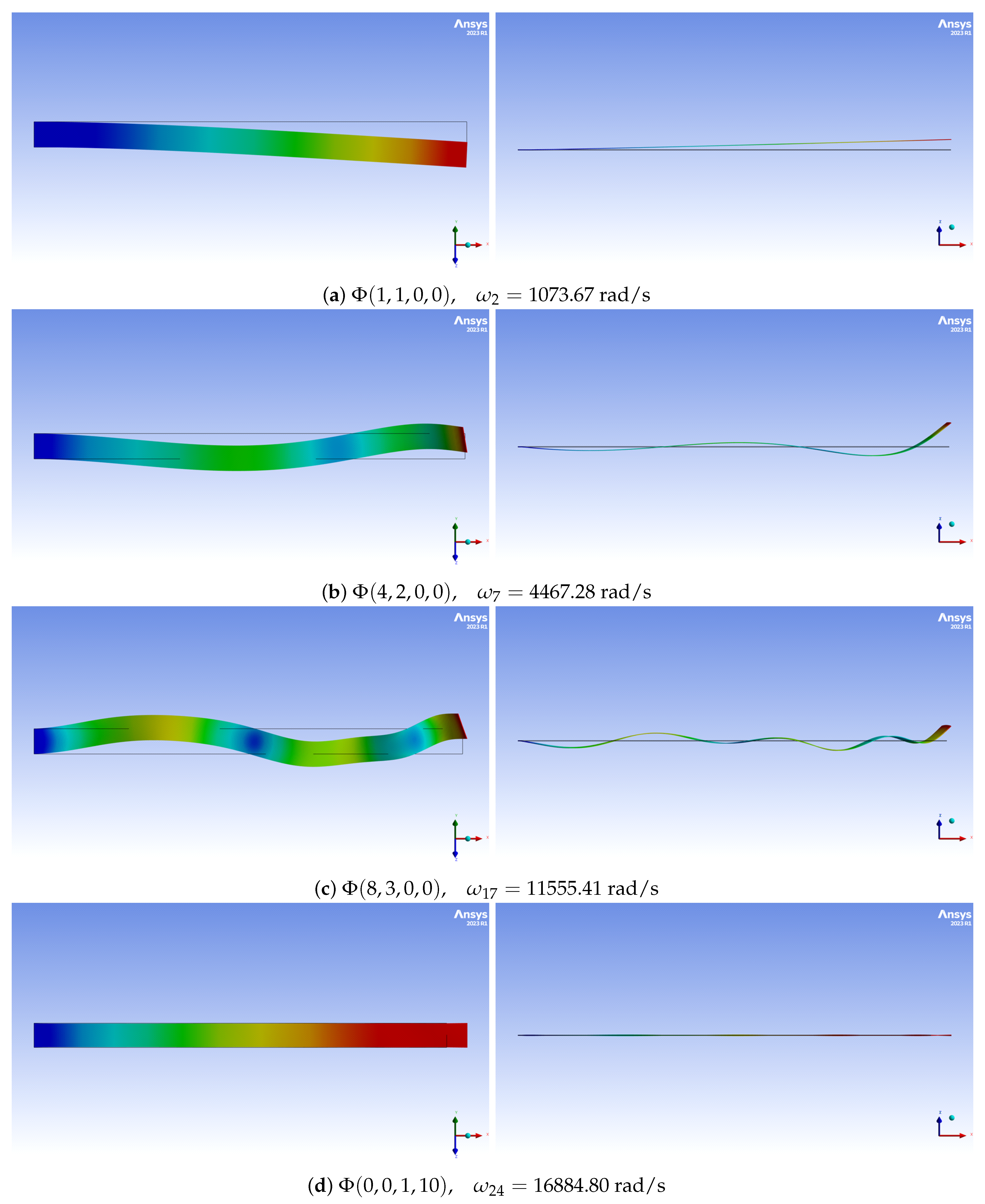
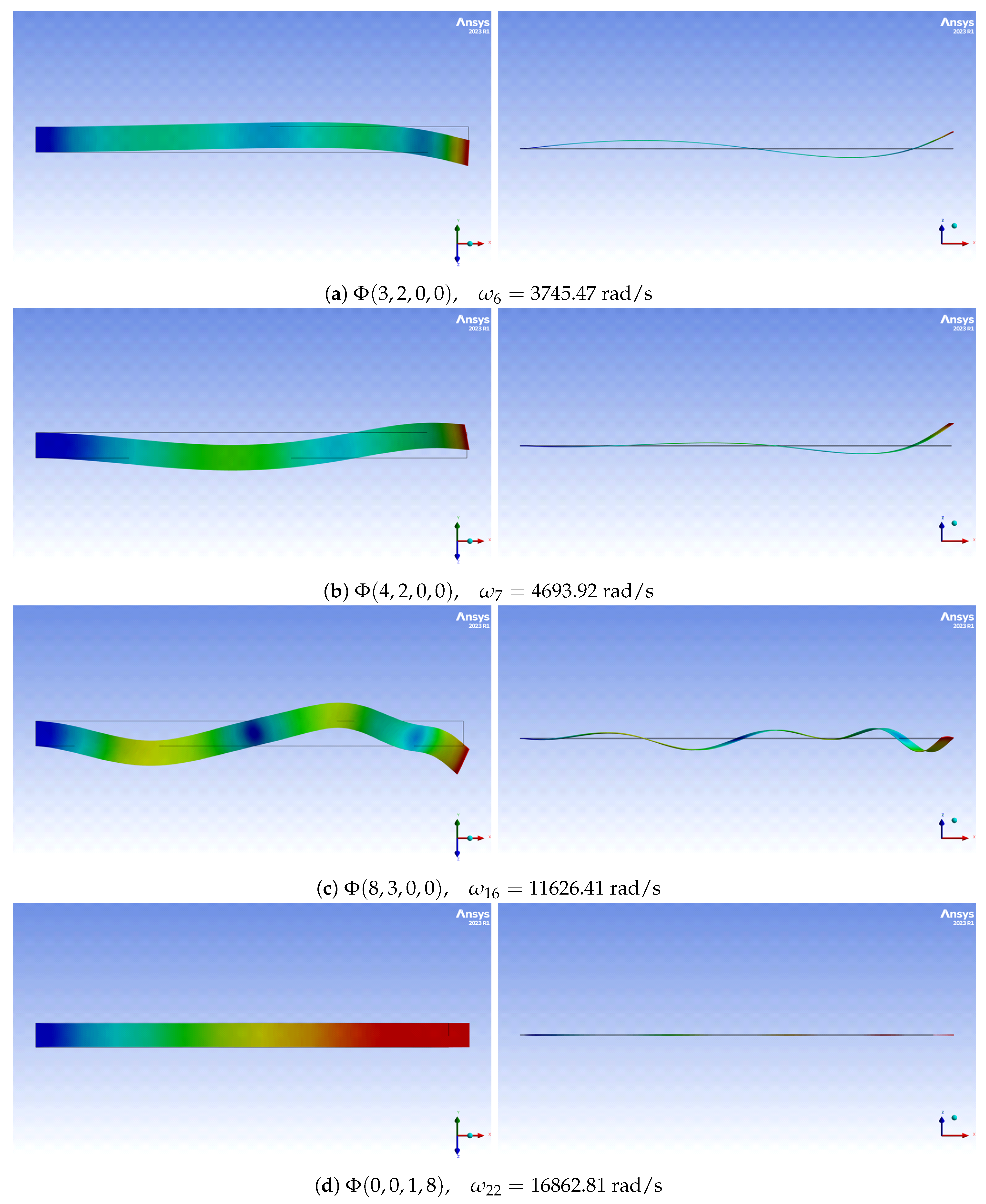
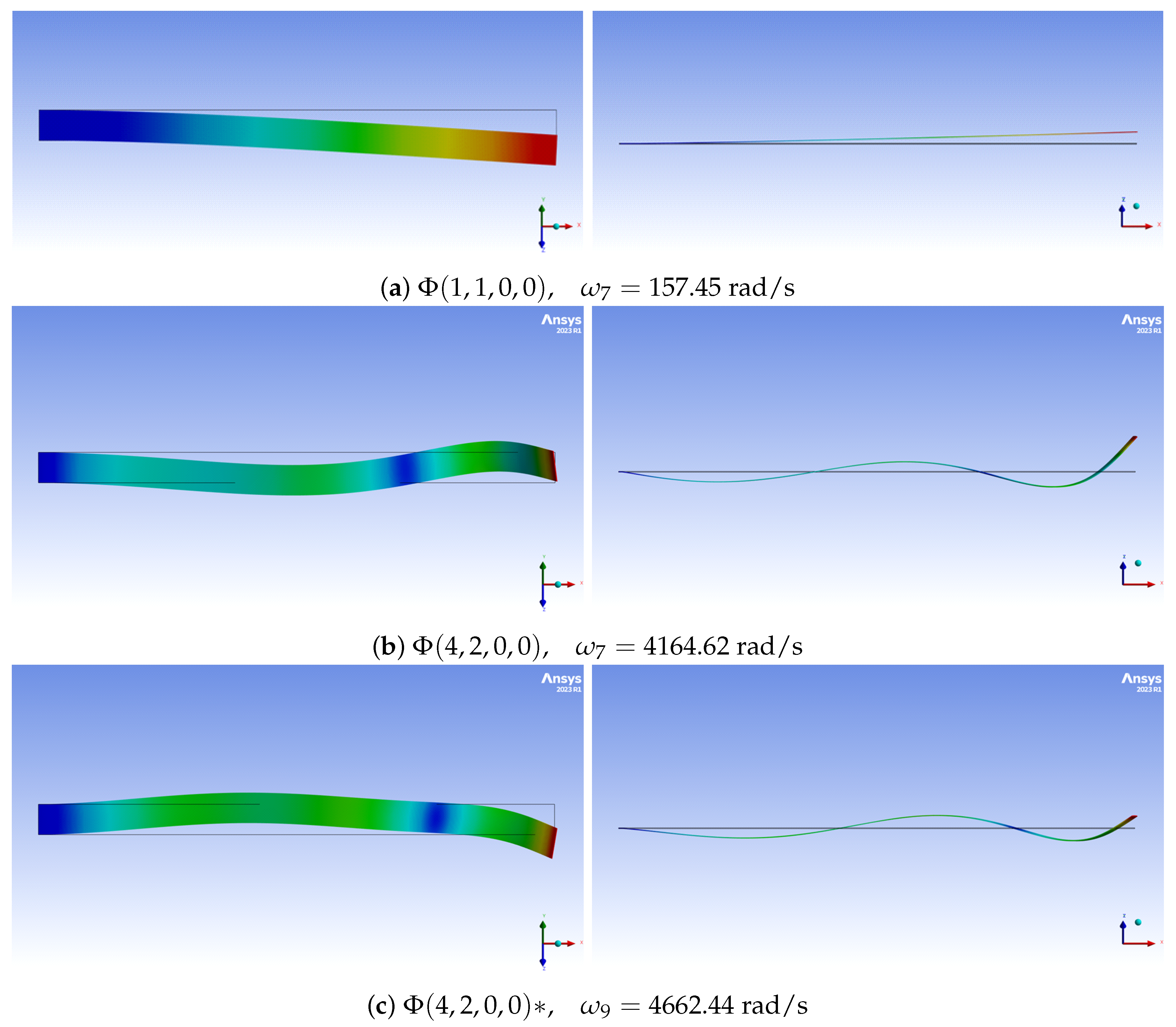
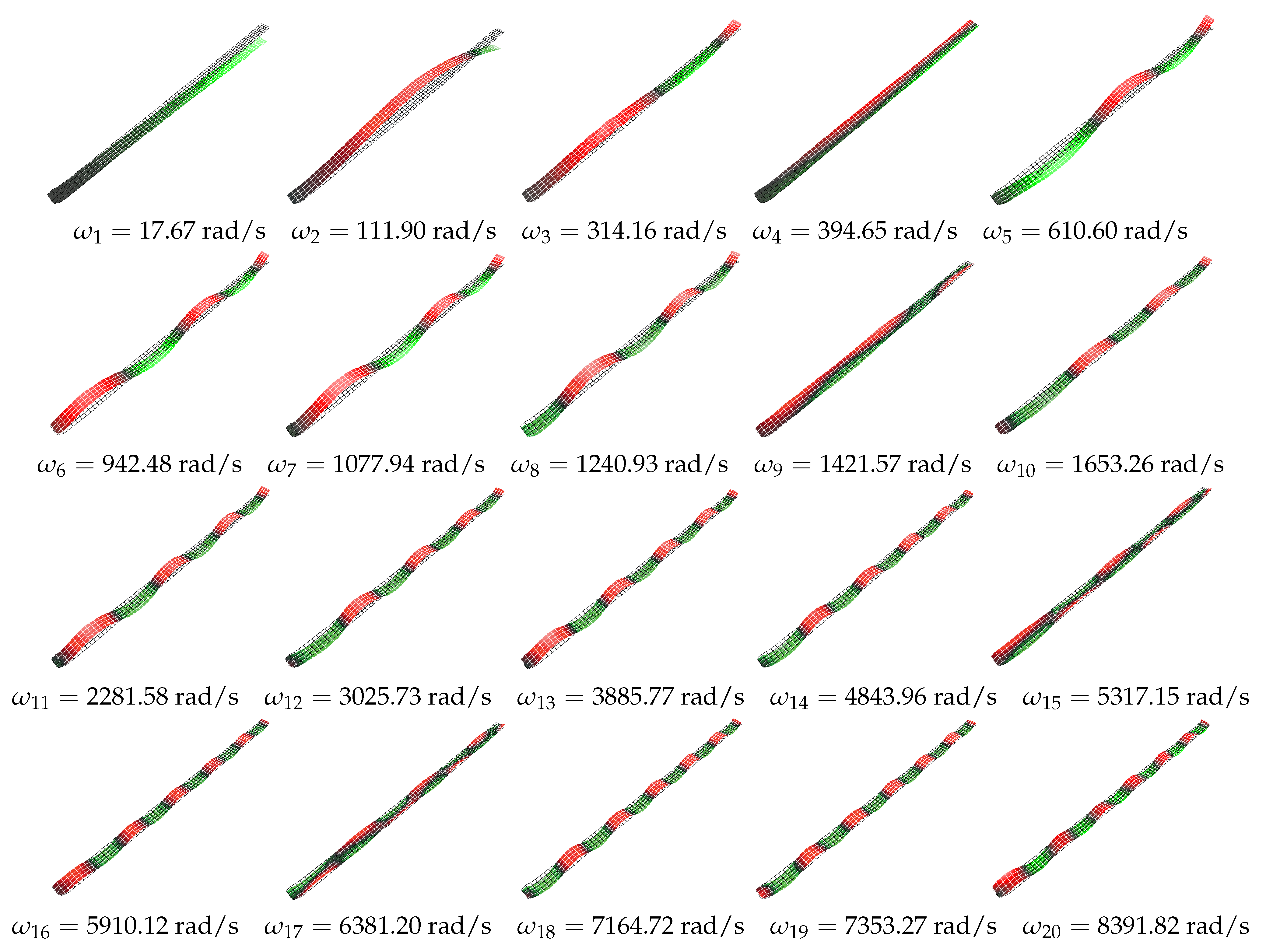
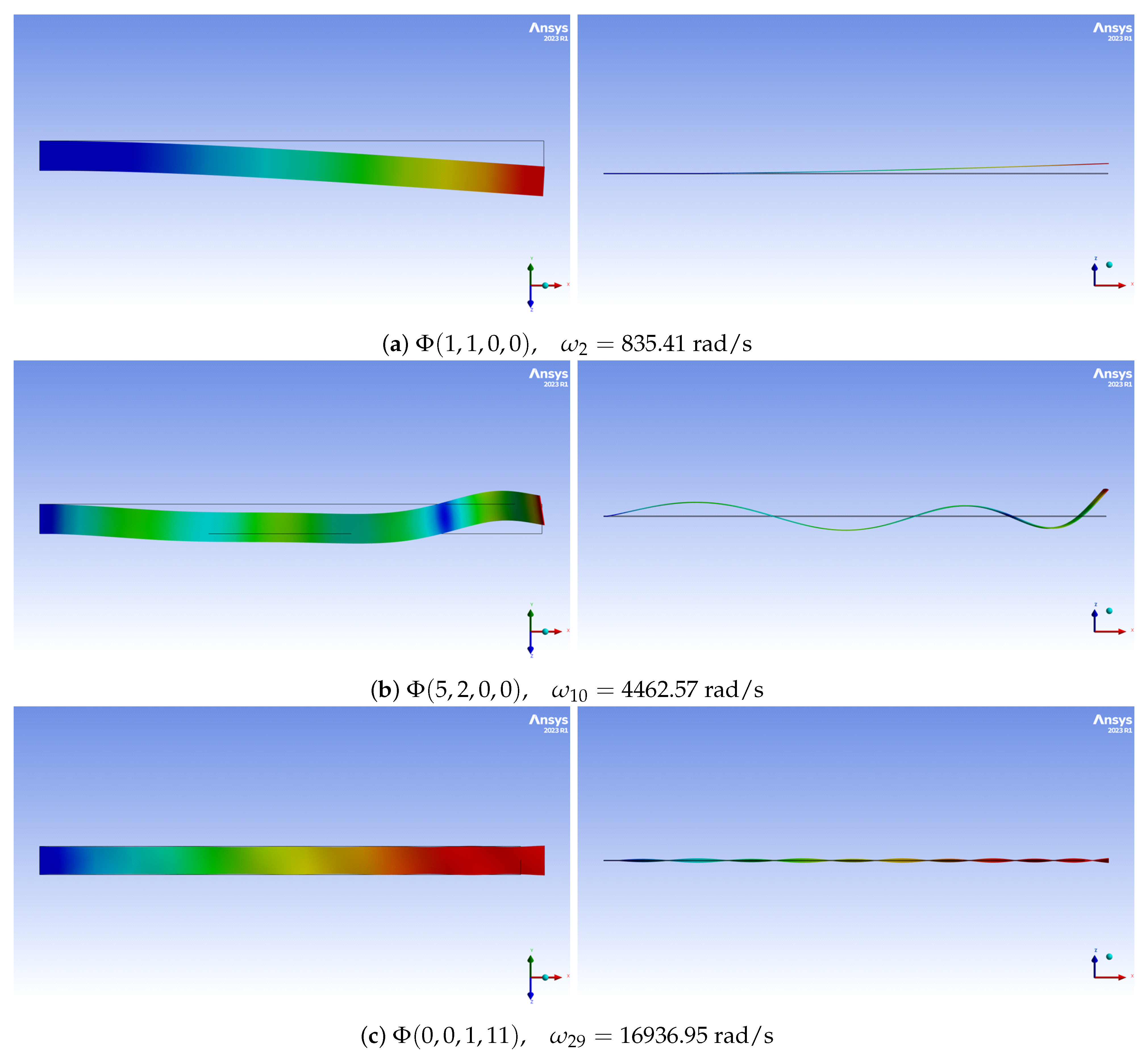
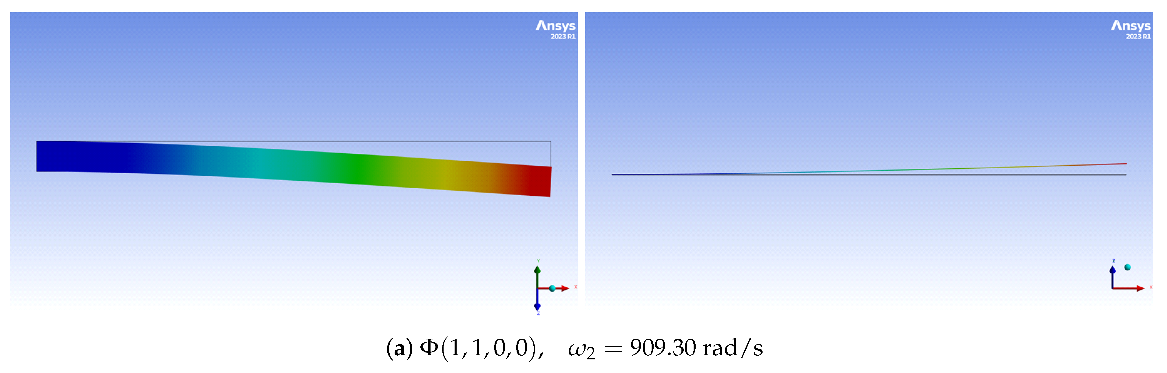
2.2. Linear Mode Shapes
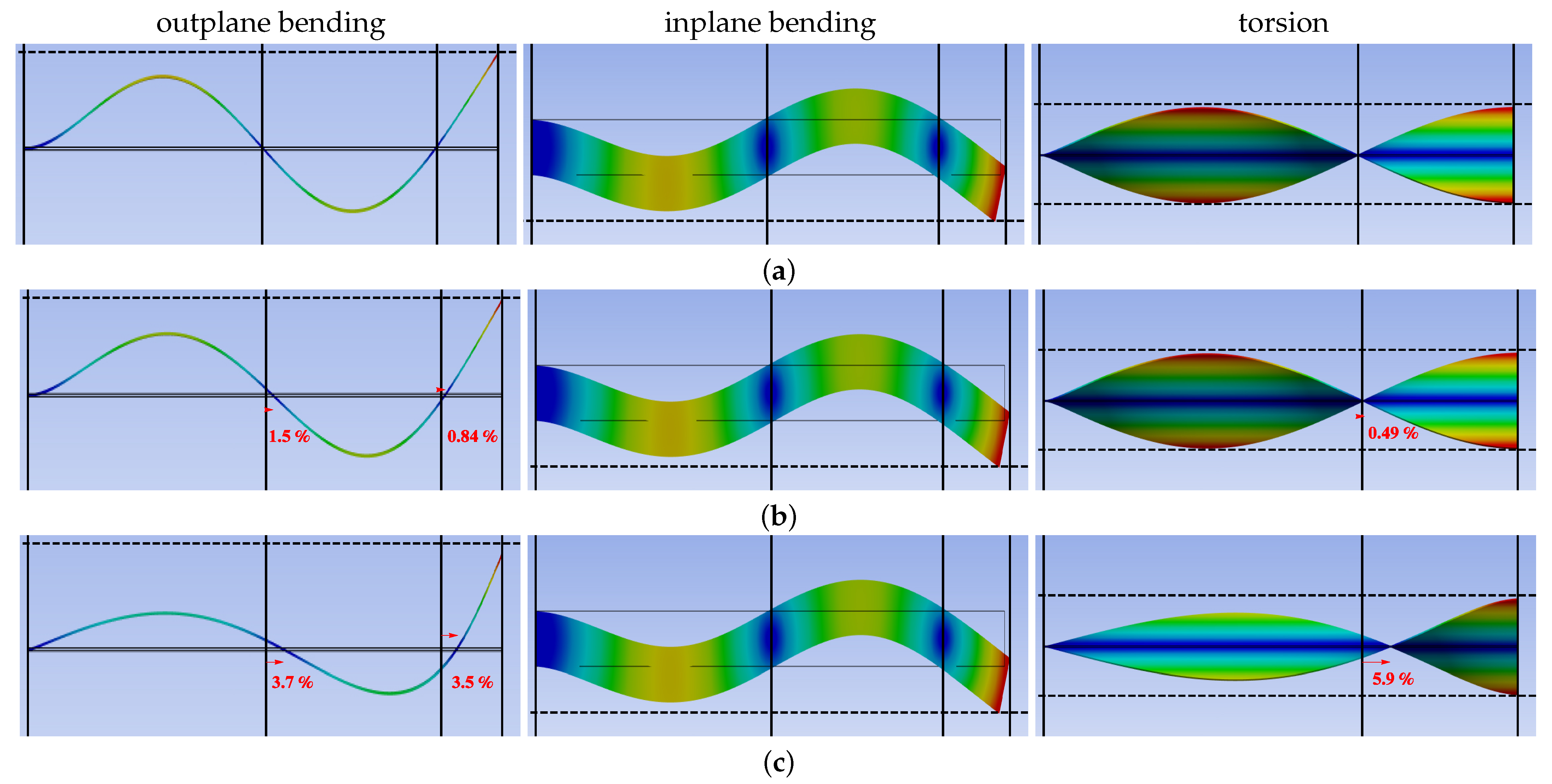
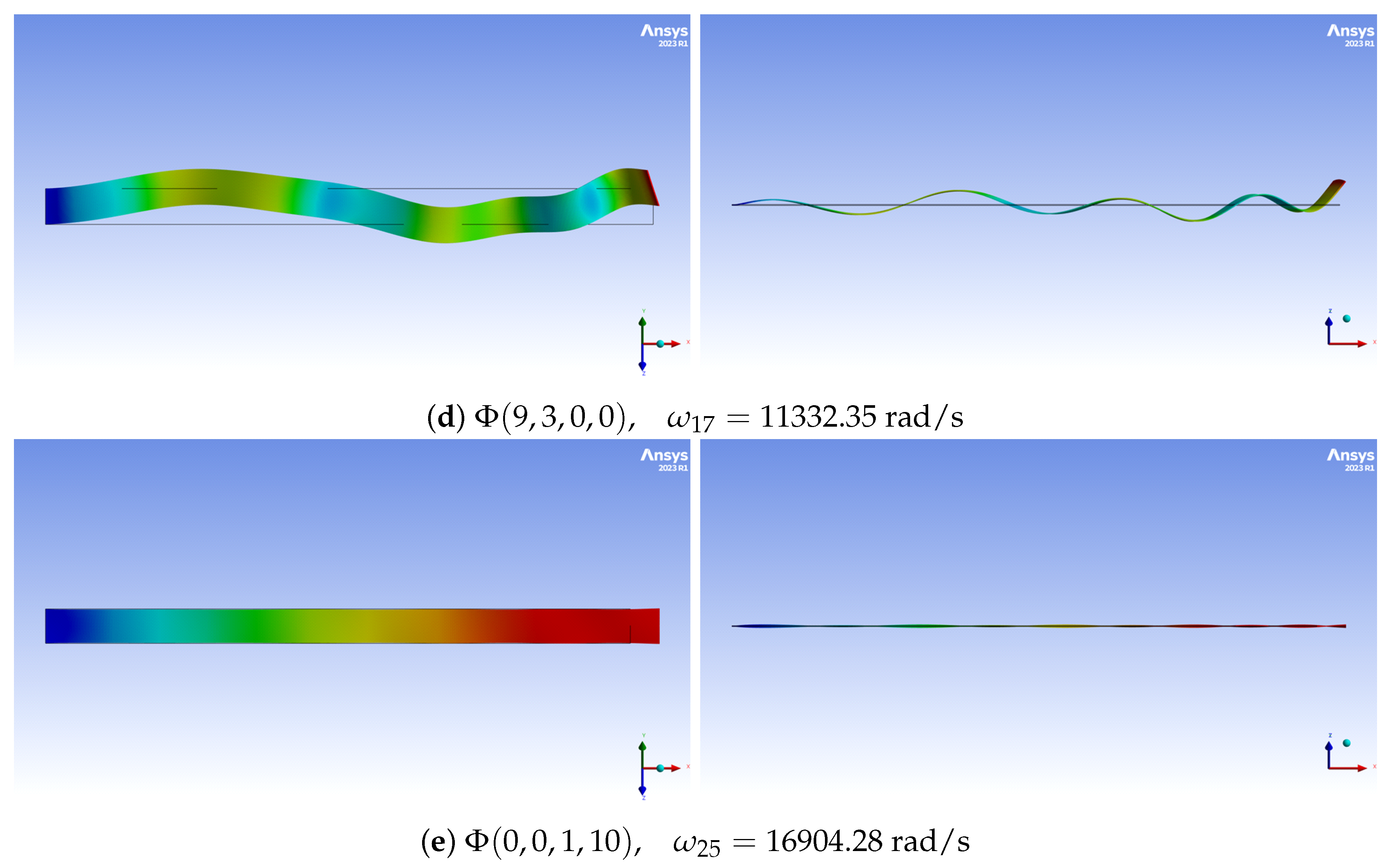
2.3. Linear Mode Couplings
3. Aerodynamic Simulations
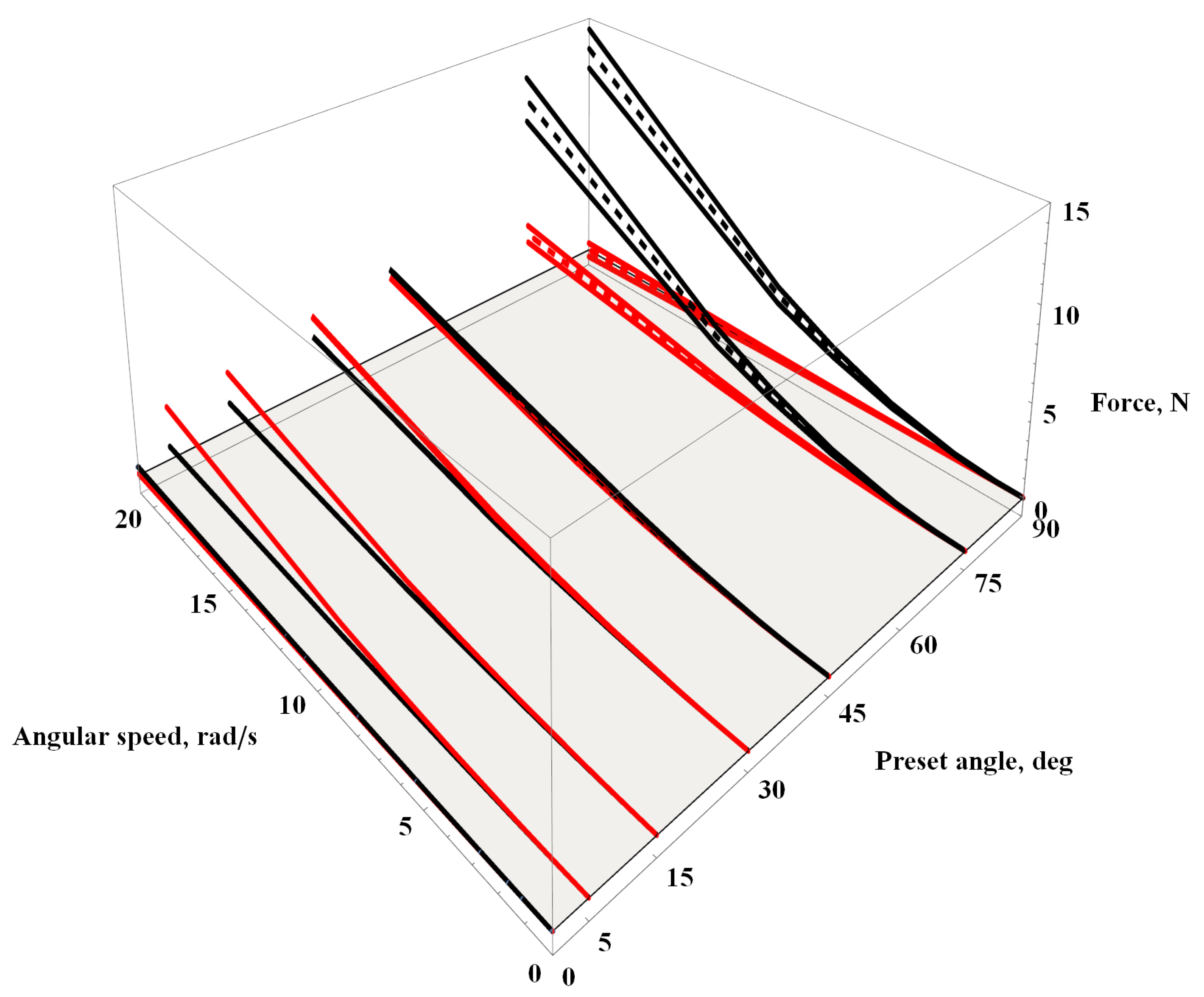
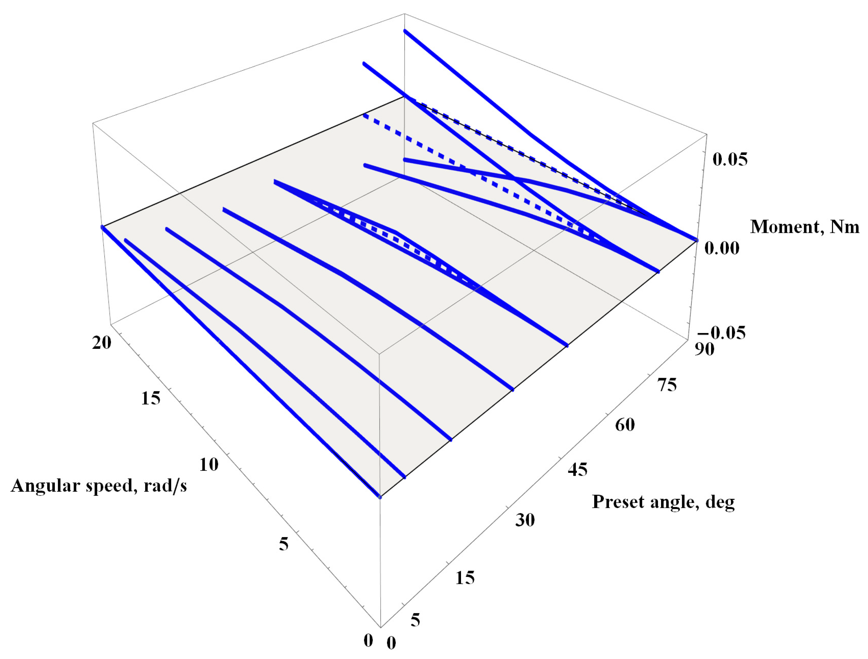
3.1. Lift/Drag Forces and Momentum
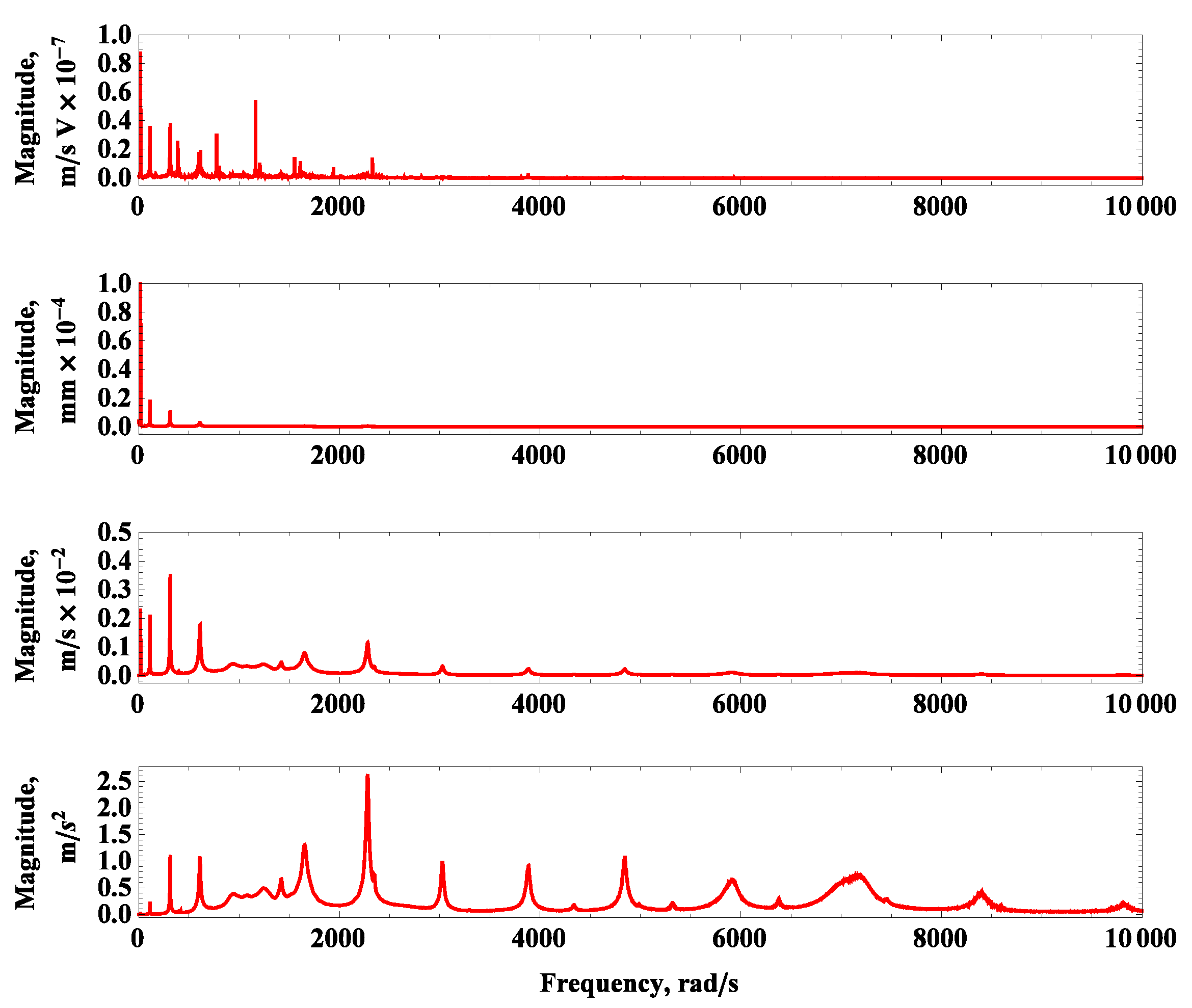
3.2. Frequency Spectra
4. Final Remarks and Further Developments
5. Conclusions
Author Contributions
Funding
Institutional Review Board Statement
Informed Consent Statement
Data Availability Statement
Conflicts of Interest
Nomeclature
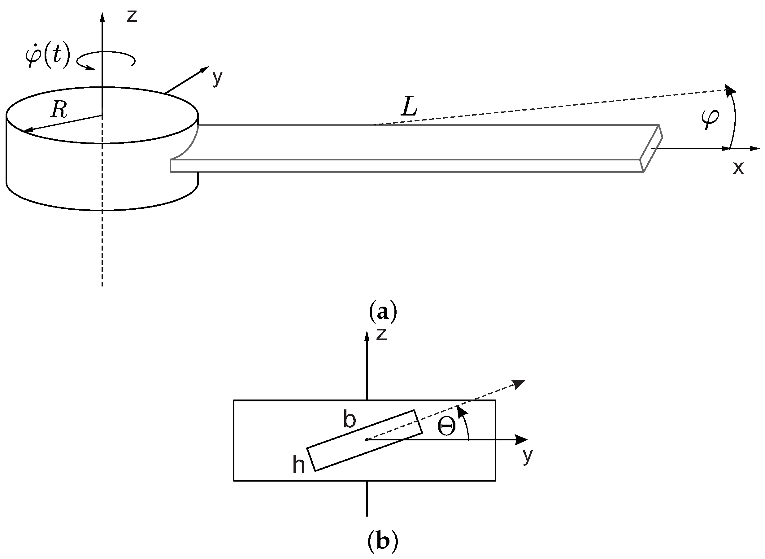
| R | Radius of a hub, mm |
| Angular velocity of a hub, rad/s | |
| L | Length of a beam, mm |
| b | Width of a beam, mm |
| h | Height of a beam, mm |
| Preset angle of a beam, | |
| Effective density of a composite beam, kg/m | |
| Mass per unit length of a beam, kg/m | |
| E | Effective Young modulus of a beam, GPa |
| G | Effective shear modulus of a beam, GPa |
| Effective Poisson’s ratio of a beam, - | |
| i | Notation for out-of-plane bending deformation of a beam, - |
| j | Notation for in-plane bending deformation of a beam, - |
| k | Notation for longitudinal deformation of a beam, - |
| l | Notation for torsional deformation of a beam, - |
| , , , | linear mode shape projections, m, m, m, rad |
| – | Normalized amplitudes of ith linear mode shape, m |
| – | Normalized amplitudes of jth linear mode shape, m |
| – | Normalized amplitudes of kth linear mode shape, m |
| – | Normalized amplitudes of lth linear mode shape, rad |
| , , , | Characteristic coefficients for ith, jth, kth and lth linear mode shape, respectively, 1/m, 1/m, 1/m, 1/rad |
| Linearly coupled mode | |
| nth natural frequency of a beam, rad/s | |
| Linearly coupled mode shape, m, m, m, rad | |
| Weights of a linearly coupled mode shape, - | |
| v | Air flow velocity, m/s |
Appendix A


References
- Carrera, E.; Pagani, A.; Petrolo, M.; Zappino, E. Recent developments on refined theories for beams with applications. Mech. Eng. Rev. 2015, 2, 14-00298. [Google Scholar] [CrossRef]
- Wang, D.; Chen, Y.; Wiercigroch, M.; Cao, Q. Bifurcation and dynamic response analysis of rotating blade excited by upstream vortices. Appl. Math. Mech. 2016, 37, 1251–1274. [Google Scholar] [CrossRef]
- Lenci, S.; Clementi, F.; Rega, G. Comparing nonlinear free vibrations of Timoshenko beams with mechanical or geometric curvature definition. Procedia IUTAM 2017, 20, 34–41. [Google Scholar] [CrossRef]
- Babilio, E.; Lenci, S. Consequences of different definitions of bending curvature on nonlinear dynamics of beams. Procedia Eng. 2017, 199, 1411–1416. [Google Scholar] [CrossRef]
- Lacarbonara, W.; Arvin, H.; Bakhtiari-Nejad, F. A geometrically exact approach to the overall dynamics of elastic rotating blades—Part 1: Linear modal properties. Nonlinear Dyn. 2012, 70, 659–675. [Google Scholar] [CrossRef]
- Arvin, H.; Lacarbonara, W.; Bakhtiari-Nejad, F. A geometrically exact approach to the overall dynamics of elastic rotating blades—Part 2: Flapping nonlinear normal modes. Nonlinear Dyn. 2012, 70, 2279–2301. [Google Scholar] [CrossRef]
- Thomas, O.; Sénéchal, A.; Deü, J.F. Hardening/softening behavior and reduced order modeling of nonlinear vibrations of rotating cantilever beams. Nonlinear Dyn. 2016, 86, 1293–1318. [Google Scholar] [CrossRef]
- Stoykov, S.; Ribeiro, P. Vibration analysis of rotating 3D beams by the p-version finite element method. Finite Elem. Anal. Des. 2013, 65, 76–88. [Google Scholar] [CrossRef]
- Carrera, E.; Filippi, M.; Zappino, E. Free vibration analysis of rotating composite blades via Carrera Unified Formulation. Compos. Struct. 2013, 106, 317–325. [Google Scholar] [CrossRef]
- Younesian, D.; Esmailzadeh, E. Non-linear vibration of variable speed rotating viscoelastic beams. Nonlinear Dyn. 2010, 60, 193–205. [Google Scholar] [CrossRef]
- Georgiades, F.; Latalski, J.; Warminski, J. Equations of motion of rotating composite beam with a nonconstant rotation speed and an arbitrary preset angle. Meccanica 2014, 49, 1833–1858. [Google Scholar] [CrossRef]
- Di Nino, S.; Luongo, A. Nonlinear dynamics of a base-isolated beam under turbulent wind flow. Nonlinear Dyn. 2022, 107, 1529–1544. [Google Scholar] [CrossRef]
- Elmiligui, A.; Abdol-Hamid, K.S.; Massey, S.J.; Pao, S.P. Numerical study of flow past a circular cylinder using hybrid turbulence formulations. J. Aircr. 2010, 47, 434–440. [Google Scholar] [CrossRef]
- Yao, M.H.; Chen, Y.P.; Zhang, W. Nonlinear vibrations of blade with varying rotating speed. Nonlinear Dyn. 2012, 68, 487–504. [Google Scholar] [CrossRef]
- Eftekhari, M.; Owhadi, S. Nonlinear dynamics of the rotating beam with time-varying speed under aerodynamic loads. Int. J. Dyn. Control 2022, 10, 49–68. [Google Scholar] [CrossRef]
- Warminski, J.; Kloda, L.; Latalski, J.; Mitura, A.; Kowalczuk, M. Nonlinear vibrations and time delay control of an extensible slowly rotating beam. Nonlinear Dyn. 2021, 103, 3255–3281. [Google Scholar] [CrossRef]
- Kloda, L.; Warminski, J. Nonlinear longitudinal–bending–twisting vibrations of extensible slowly rotating beam with tip mass. Int. J. Mech. Sci. 2022, 220, 107153. [Google Scholar] [CrossRef]
- Kumar, P. Modal analysis of viscoelastic three-dimensional rotating beam with generic tip mass. Eur. J. Mech.-A/Solids 2022, 96, 104734. [Google Scholar] [CrossRef]
- Huang, J.; Wang, K.; Tang, J.; Xu, J.; Song, H. An experimental study of the centrifugal hardening effect on rotating cantilever beams. Mech. Syst. Signal Process. 2022, 165, 108291. [Google Scholar] [CrossRef]
- Gawryluk, J.; Mitura, A.; Teter, A. Dynamic response of a composite beam rotating at constant speed caused by harmonic excitation with MFC actuator. Compos. Struct. 2019, 210, 657–662. [Google Scholar] [CrossRef]
- Rafiee, M.; Nitzsche, F.; Labrosse, M. Dynamics, vibration and control of rotating composite beams and blades: A critical review. Thin-Walled Struct. 2017, 119, 795–819. [Google Scholar] [CrossRef]
- Teter, A.; Gawryluk, J. Experimental modal analysis of a rotor with active composite blades. Compos. Struct. 2016, 153, 451–467. [Google Scholar] [CrossRef]
- Mitura, A.; Gawryluk, J.; Teter, A. Numerical and experimental studies on the rotating rotor with three active composite blades. Eksploat. Niezawodn. Maint. Reliab. 2017, 19, 571–579. [Google Scholar] [CrossRef]
- Warminski, J.; Latalski, J.; Szmit, Z. Vibration of a mistuned three-bladed rotor under regular and chaotic excitations. J. Theor. Appl. Mech. 2018, 56, 549–566. [Google Scholar] [CrossRef]
- Szmit, Z. Vibration, synchronization and localization of three-bladed rotor: Theoretical and experimental studies. Eur. Phys. J. Spec. Top. 2021, 230, 3615–3625. [Google Scholar] [CrossRef]
- Szmit, Z.; Kloda, L.; Kowalczuk, M.; Stachyra, G.; Warmiński, J. Experimental analysis of aerodynamic loads of three-bladed rotor. Materials 2022, 15, 3335. [Google Scholar] [CrossRef] [PubMed]
- Vannucci, P.; Verchery, G. A new method for generating fully isotropic laminates. Compos. Struct. 2002, 58, 75–82. [Google Scholar] [CrossRef]
- Warminski, J.; Kloda, L.; Lenci, S. Nonlinear vibrations of an extensional beam with tip mass in slewing motion. Meccanica 2020, 55, 2311–2335. [Google Scholar] [CrossRef]
- Ehrhardt, D.A.; Hill, T.L.; Neild, S.A.; Cooper, J.E. Veering and nonlinear interactions of a clamped beam in bending and torsion. J. Sound Vib. 2018, 416, 1–16. [Google Scholar] [CrossRef]


| E | G | |||
|---|---|---|---|---|
| kg/m3 | kg/m | GPa | GPa | (-) |
| 1350 |
Disclaimer/Publisher’s Note: The statements, opinions and data contained in all publications are solely those of the individual author(s) and contributor(s) and not of MDPI and/or the editor(s). MDPI and/or the editor(s) disclaim responsibility for any injury to people or property resulting from any ideas, methods, instructions or products referred to in the content. |
© 2023 by the authors. Licensee MDPI, Basel, Switzerland. This article is an open access article distributed under the terms and conditions of the Creative Commons Attribution (CC BY) license (https://creativecommons.org/licenses/by/4.0/).
Share and Cite
Stachyra, G.; Kloda, L.; Szmit, Z. Coupled Modal Analysis and Aerodynamics of Rotating Composite Beam. Materials 2023, 16, 7356. https://doi.org/10.3390/ma16237356
Stachyra G, Kloda L, Szmit Z. Coupled Modal Analysis and Aerodynamics of Rotating Composite Beam. Materials. 2023; 16(23):7356. https://doi.org/10.3390/ma16237356
Chicago/Turabian StyleStachyra, Grzegorz, Lukasz Kloda, and Zofia Szmit. 2023. "Coupled Modal Analysis and Aerodynamics of Rotating Composite Beam" Materials 16, no. 23: 7356. https://doi.org/10.3390/ma16237356
APA StyleStachyra, G., Kloda, L., & Szmit, Z. (2023). Coupled Modal Analysis and Aerodynamics of Rotating Composite Beam. Materials, 16(23), 7356. https://doi.org/10.3390/ma16237356