
Torsional Behavior of Concrete-Filled Circular Steel Tubes Strengthened with CFRP

Abstract
:1. Introduction
2. Experimental Study
2.1. Material Properties of Specimens
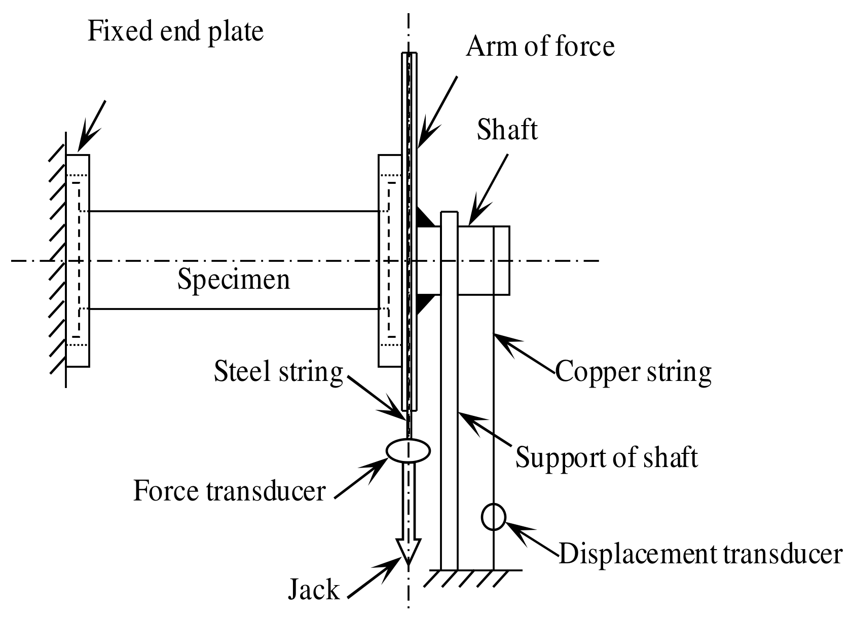
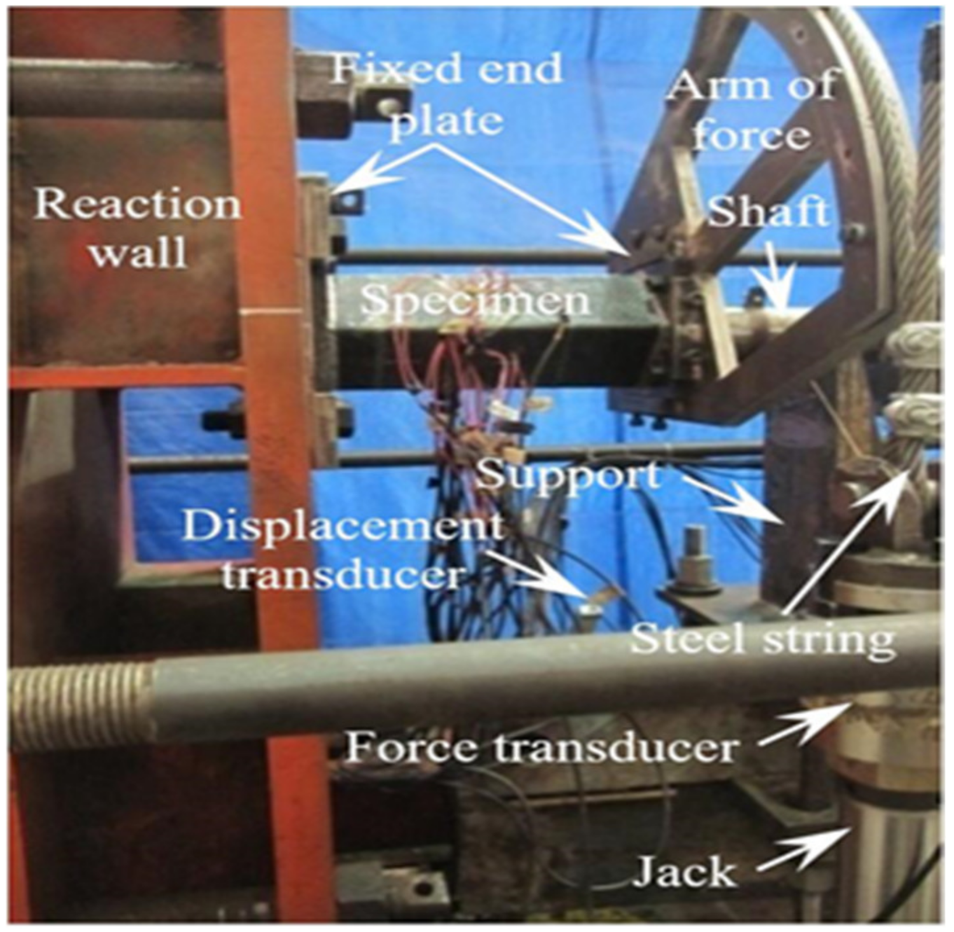
2.2. Loading and Measurement
2.3. Experimental Phenomenon
2.4. Analysis of Test Results
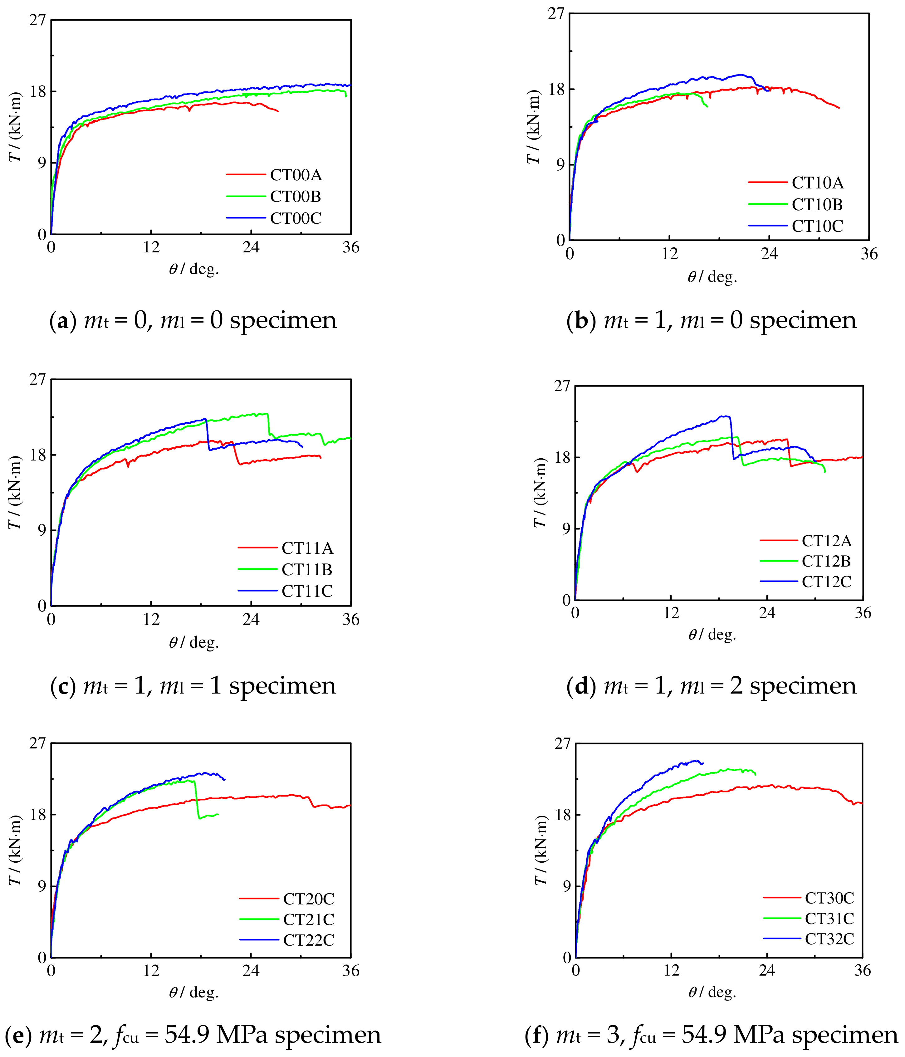
2.4.1. Moment–Rotation Curve
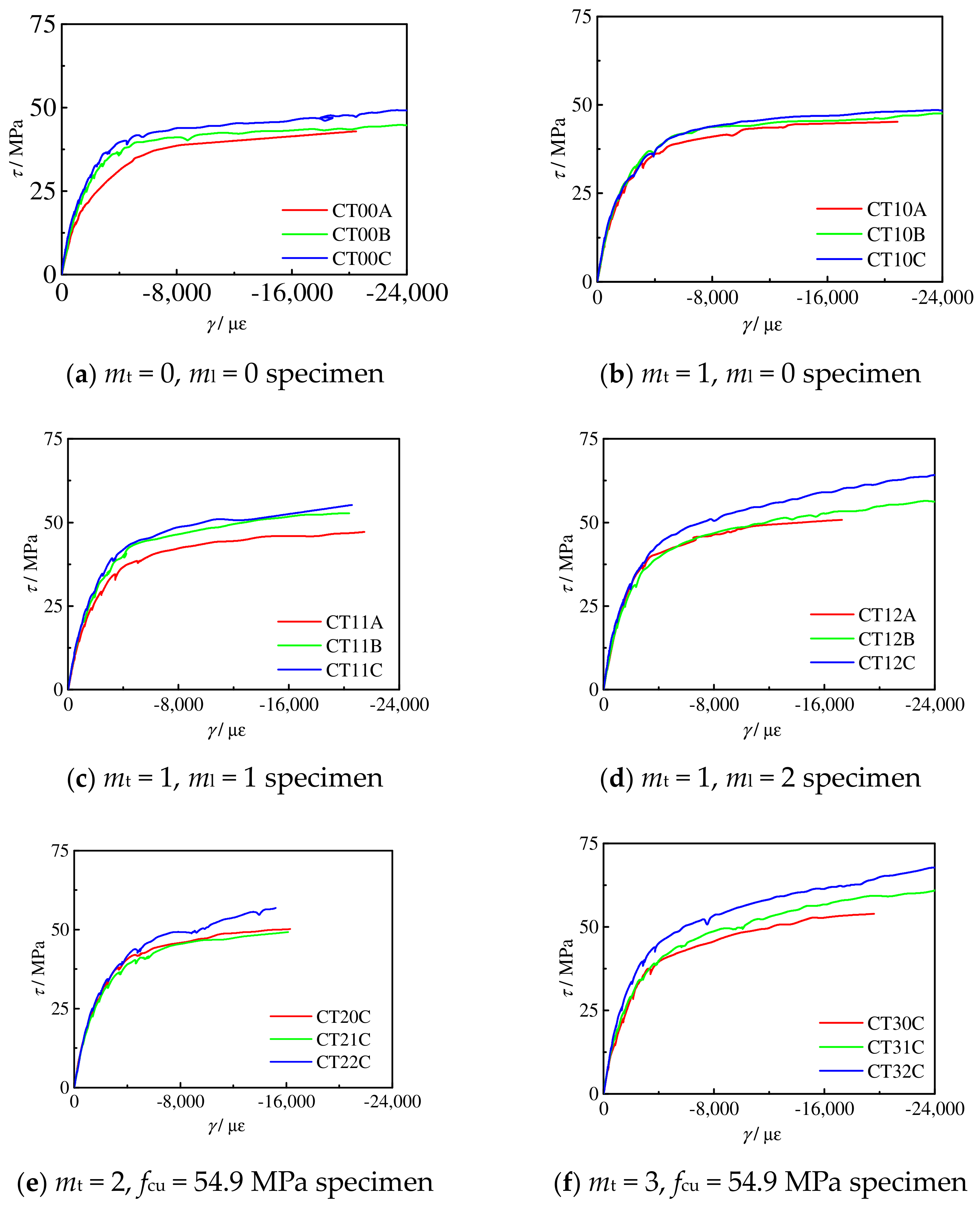
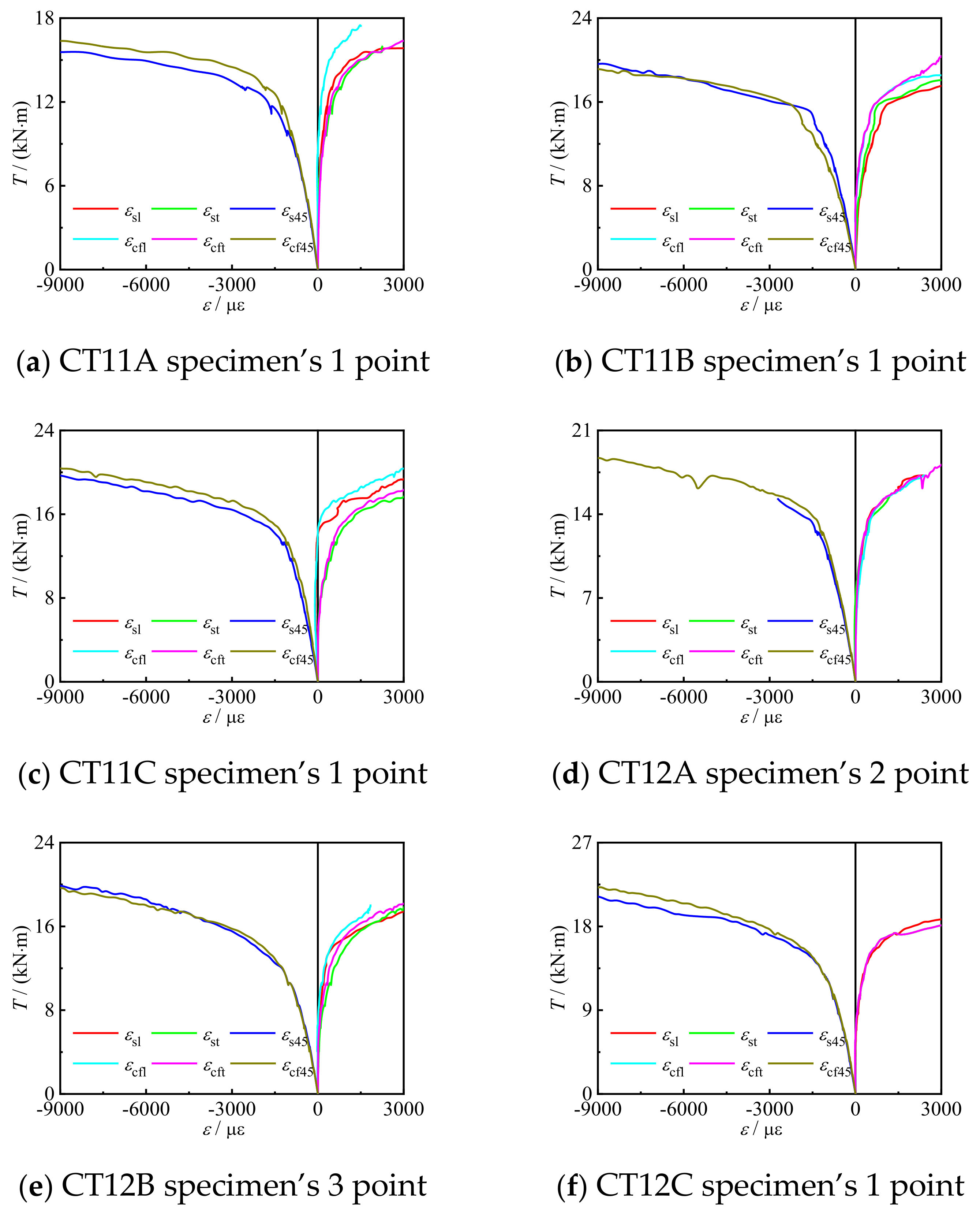
2.4.2. Shear Stress–Strain Curve
2.4.3. Collaborative Work of Steel Tube and CFRP
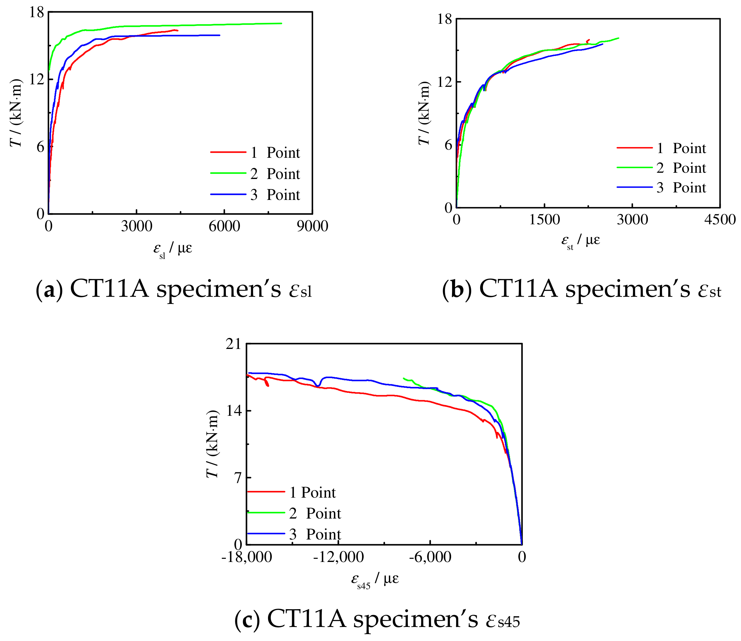
2.4.4. Plane Section Assumption
3. FE Model
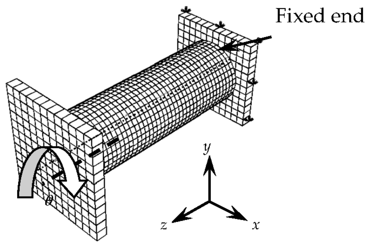
3.1. Finite Element Calculation Model
3.2. Comparison between Simulation Results and Test Results
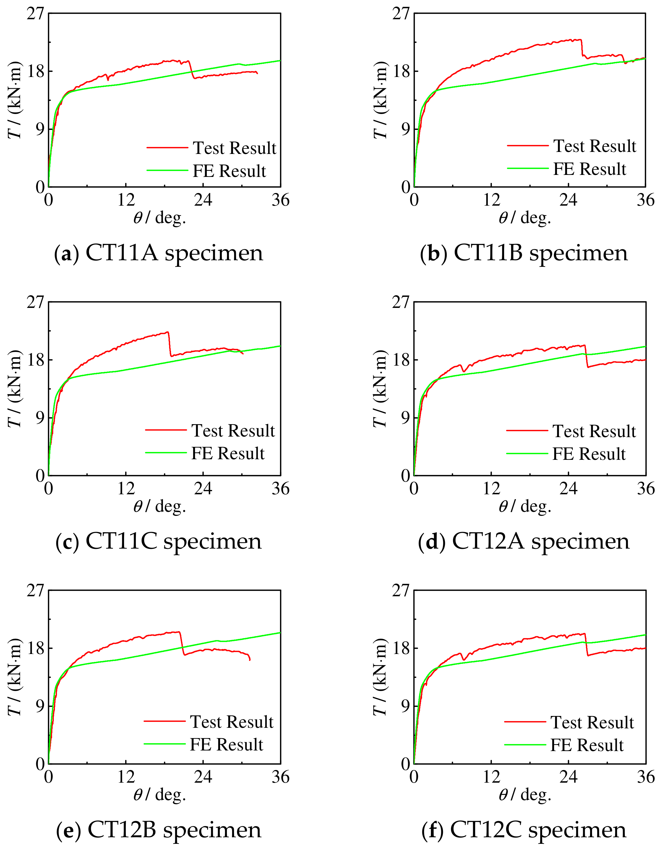
3.2.1. T-θ Curve
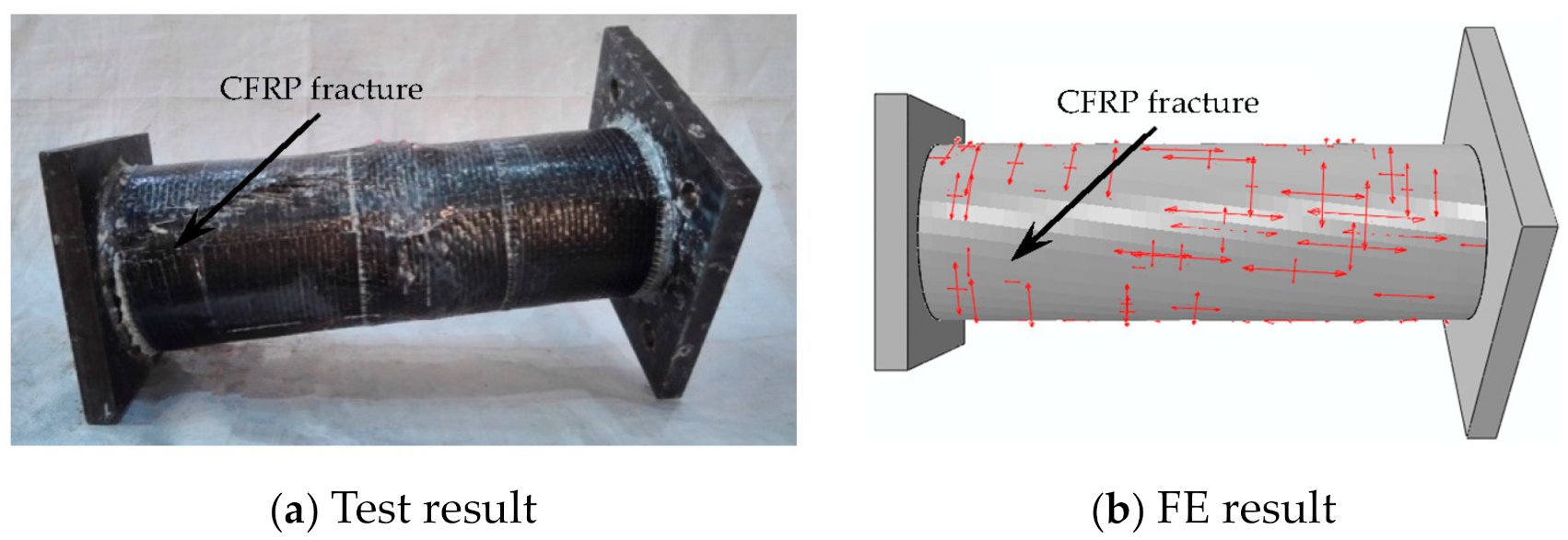
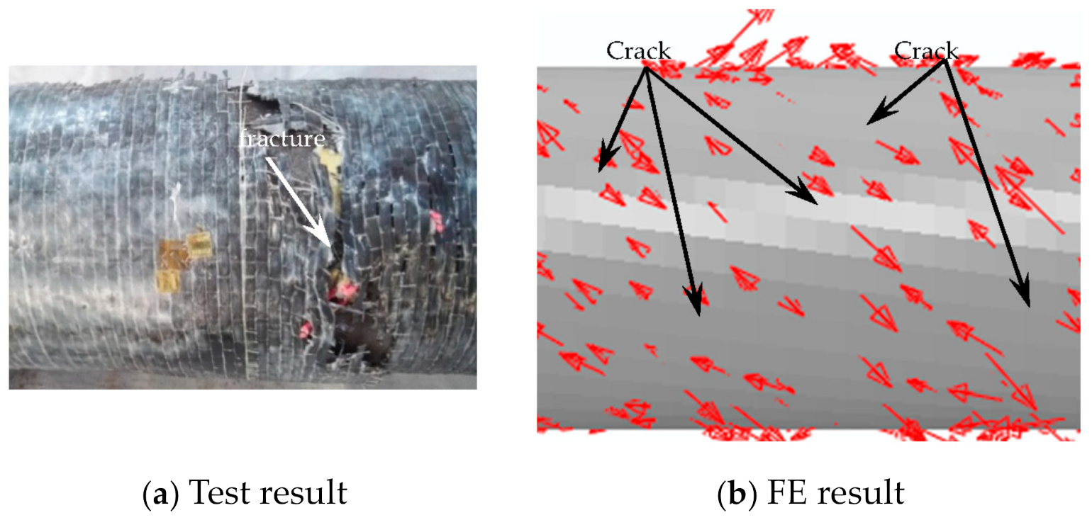
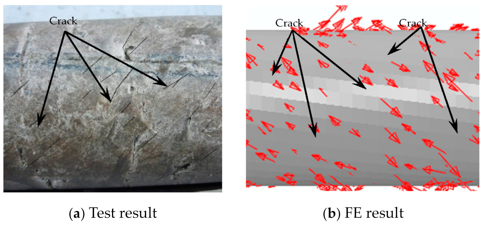
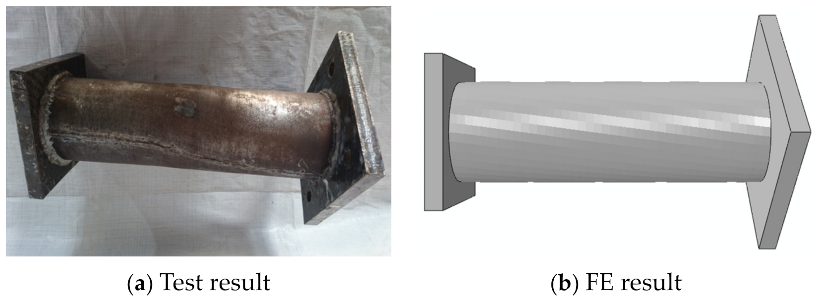
3.2.2. Failure Mode
4. Analysis of the Whole Process of Stress
4.1. Stress Distribution of Steel Tube and Concrete
4.2. Concrete Stress
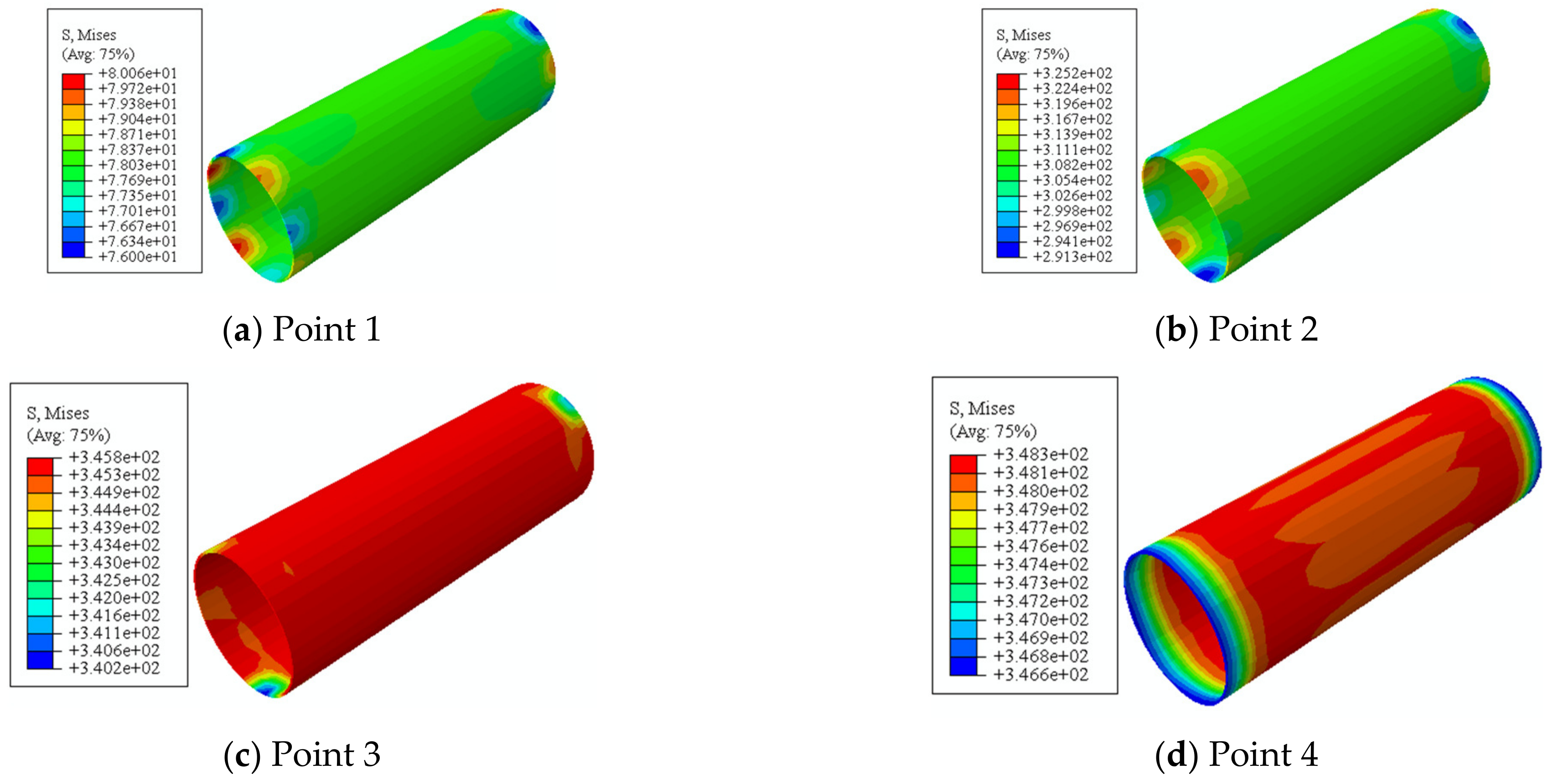
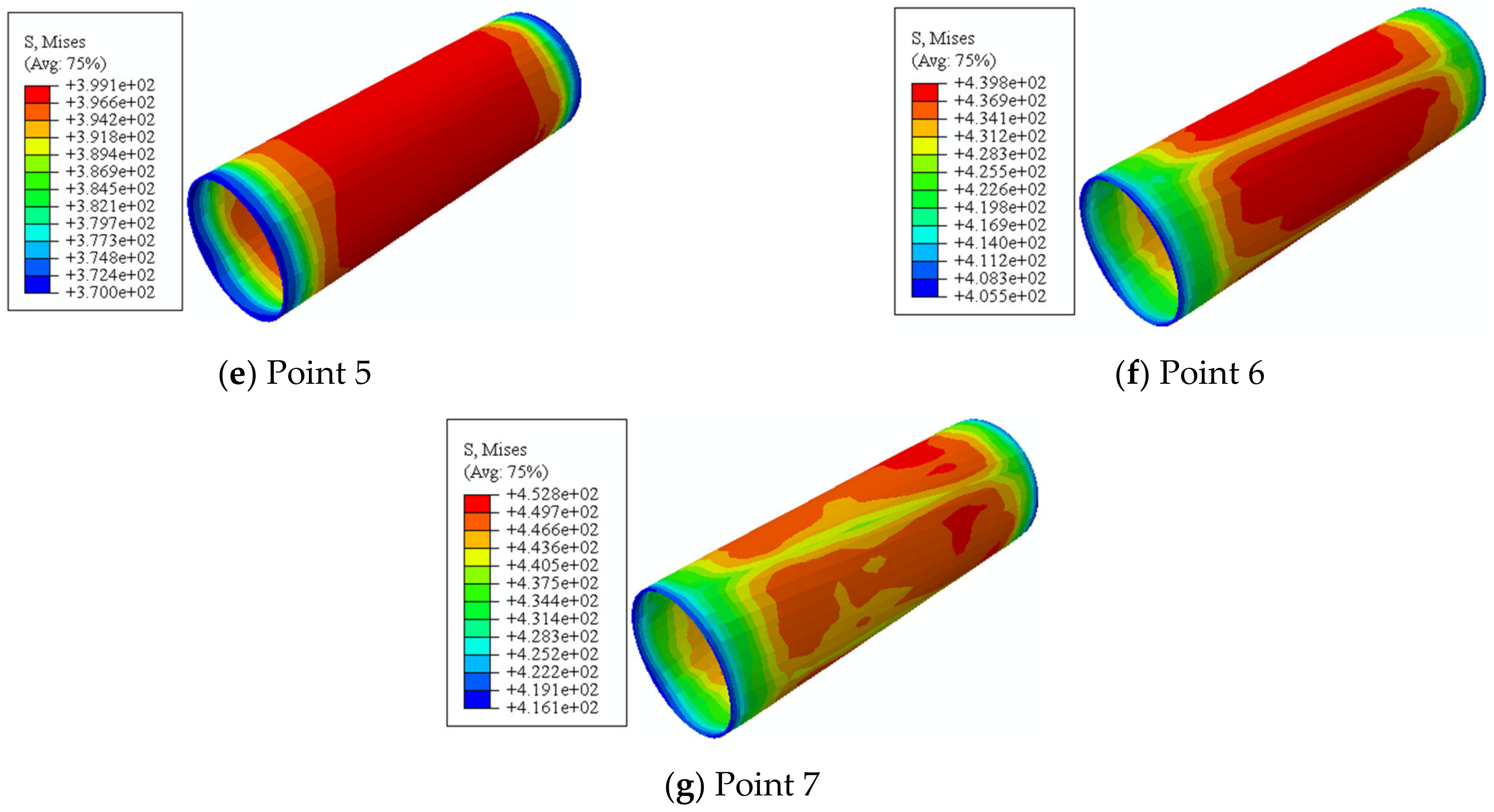
4.3. Steel Tube Stress
4.4. CFRP Stress
5. Parameter Analysis
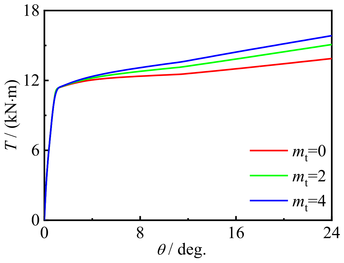
5.1. Influence of CFRP Layers
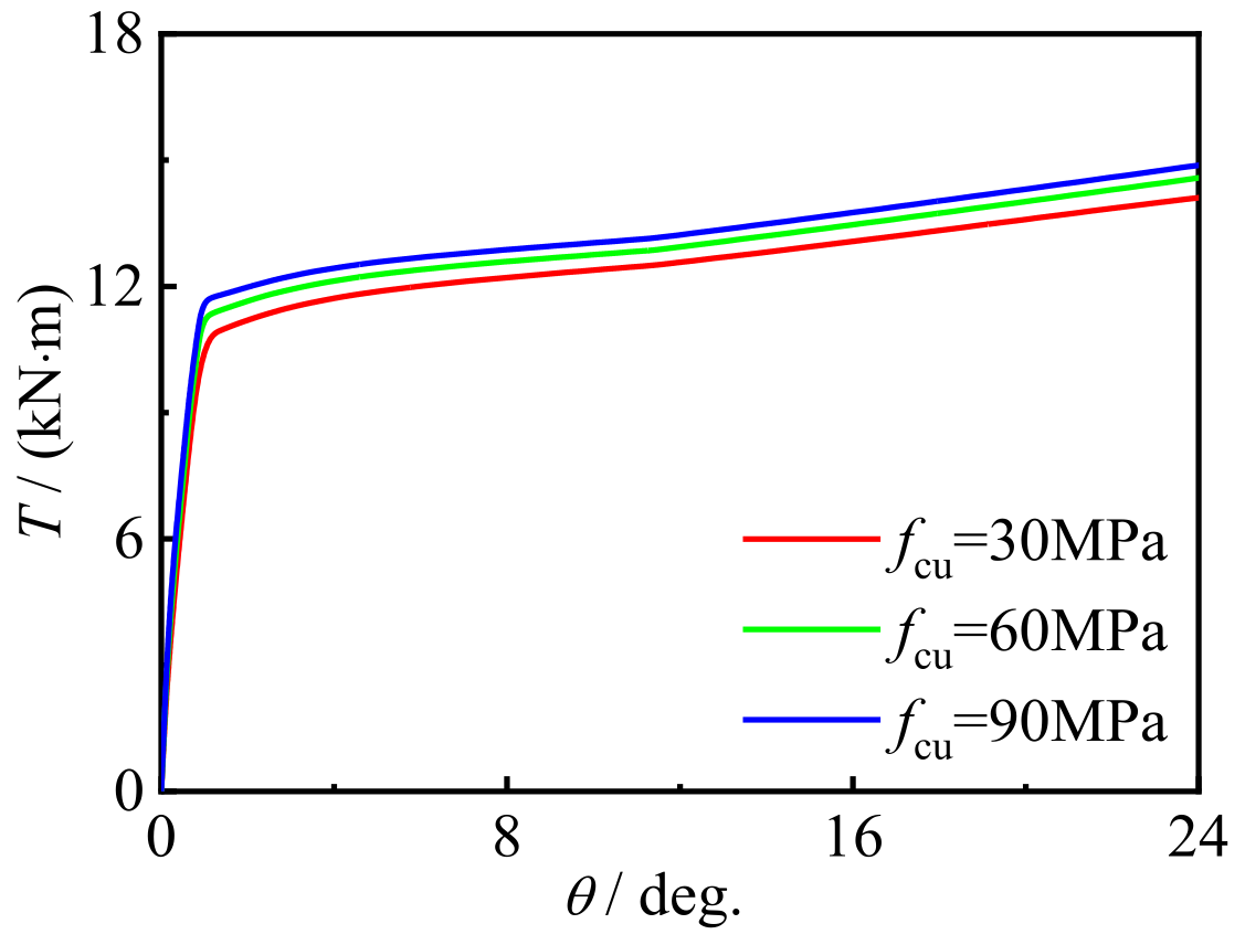
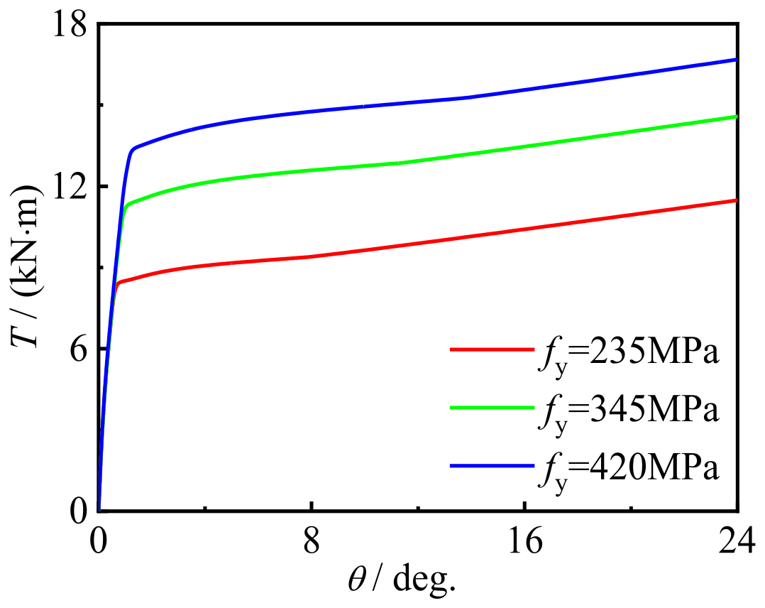
5.2. Effect of Material Strength
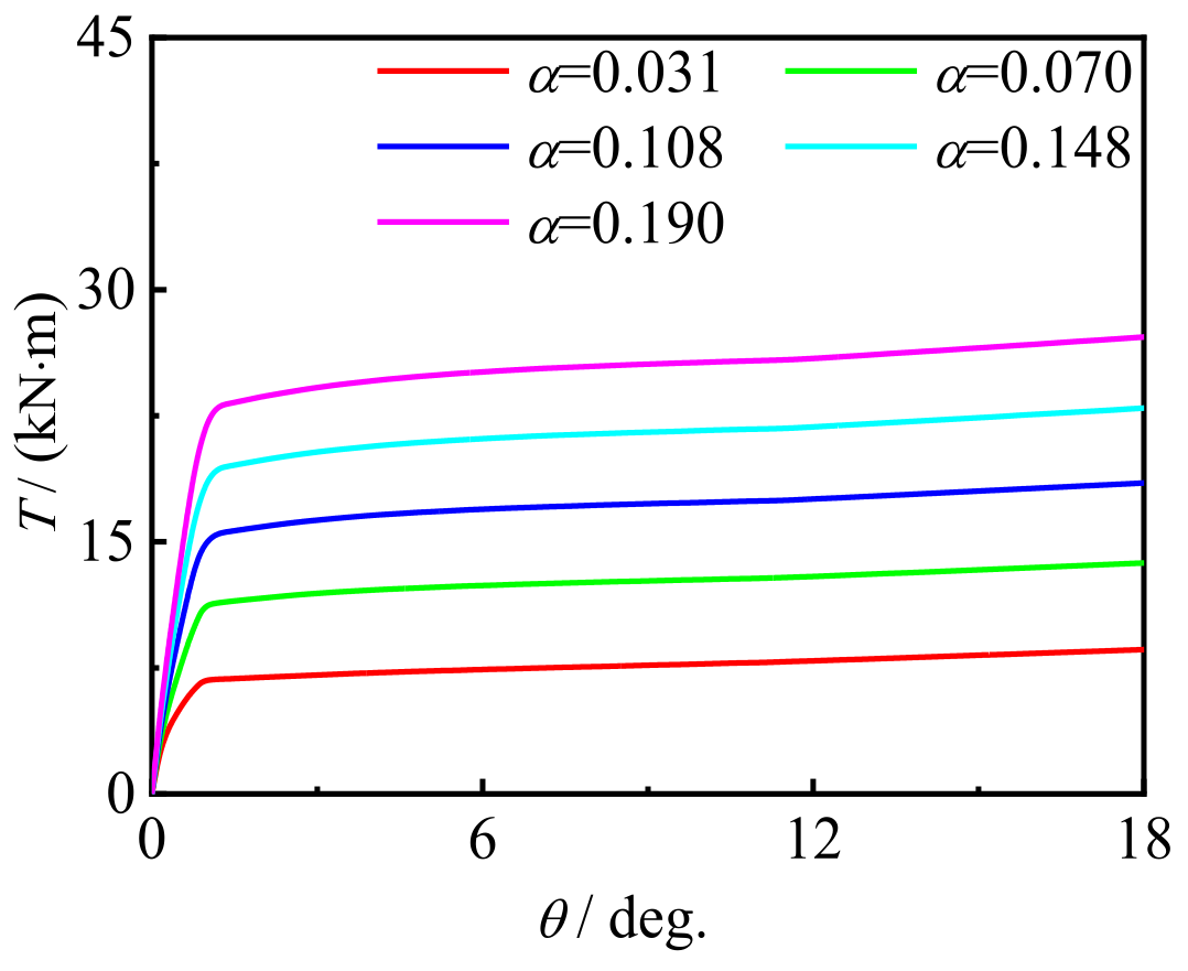
5.3. Effect of Steel Content
6. Torsional Bearing Capacity
6.1. Definition of Torsional Capacity
6.2. Calculation Expression
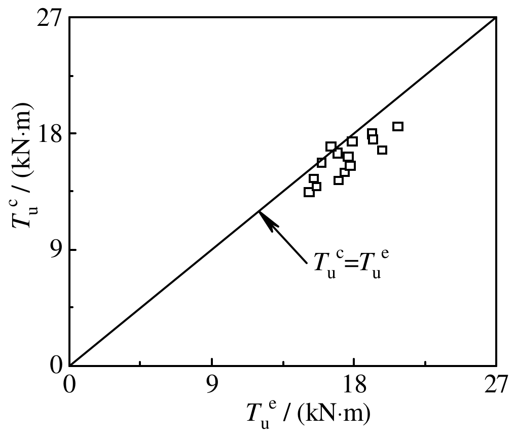
6.3. Validation of Expressions
7. Conclusions
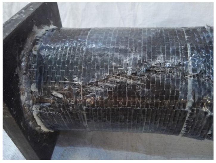
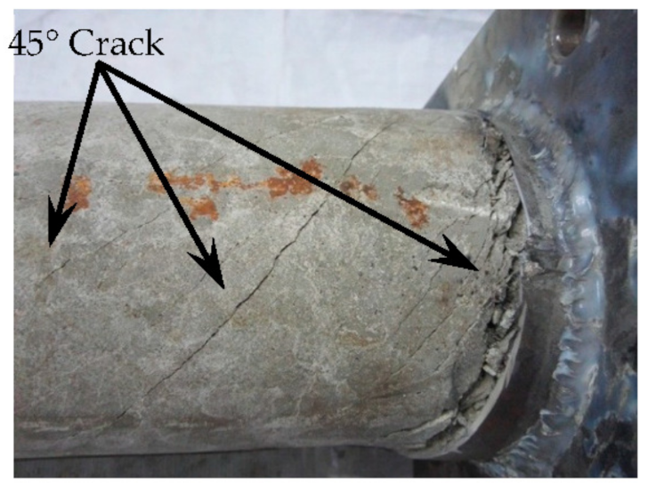
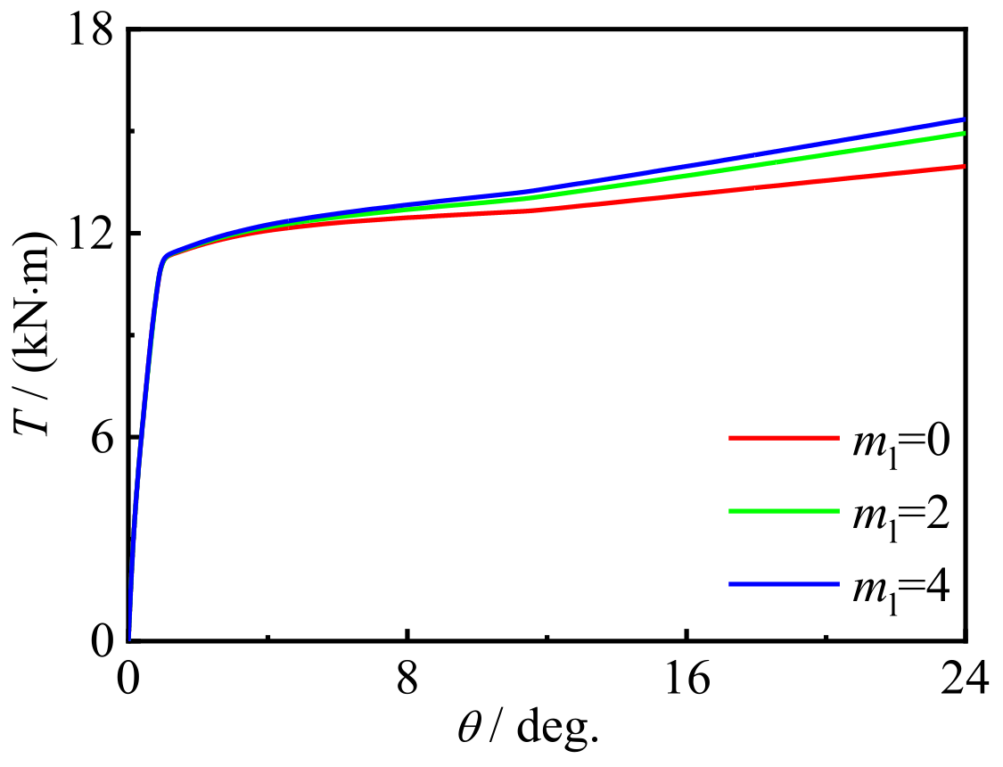
- The typical T-θ curve of the CFRP concrete-filled steel tubule is given. The curve is characterized by the elastic stage from the beginning of loading to the cracking of concrete. At this time, the torque is borne by the outer tube and concrete, and the T-θ curve at this stage is linear. When the concrete cracks appear, the specimen enters the elastic–plastic stage. At this time, with the continuous increase in torque, the concrete cracks gradually develop, the concrete continues to withdraw from its load-bearing function, the torsional stiffness gradually decreases, and most of the torque is borne by the steel tube. When most of the concrete no longer contributes to the structural load, the specimen enters the plastic reinforcement stage. Because of the restraint effect of the outer tube, the broken concrete is still whole, and the buckling of the steel tube is restrained. The steep drop in the T-θ curve is due to the fracture of the transverse and longitudinal carbon fibers, which also shows that CFRP CFST has stronger torsional resistance than CFST alone.
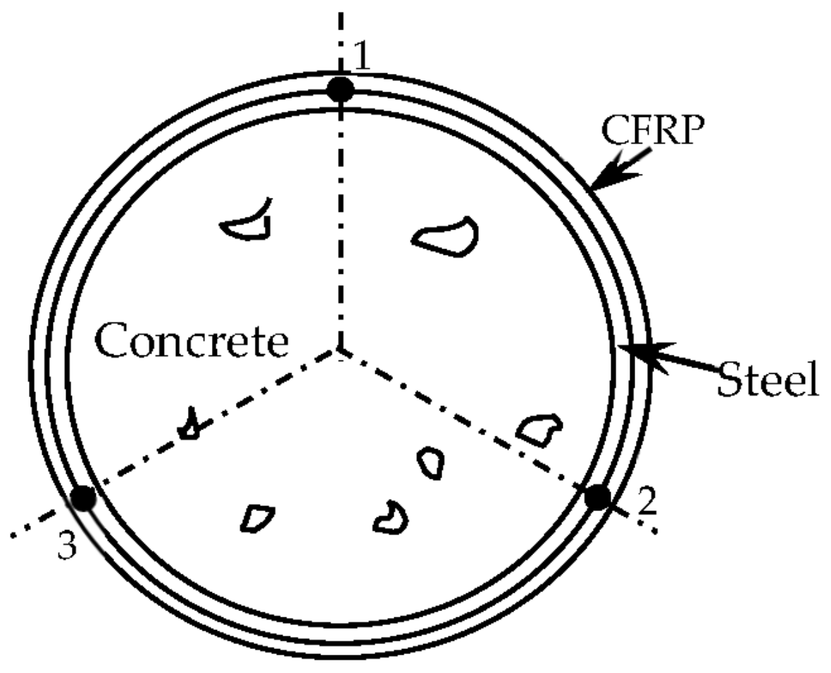
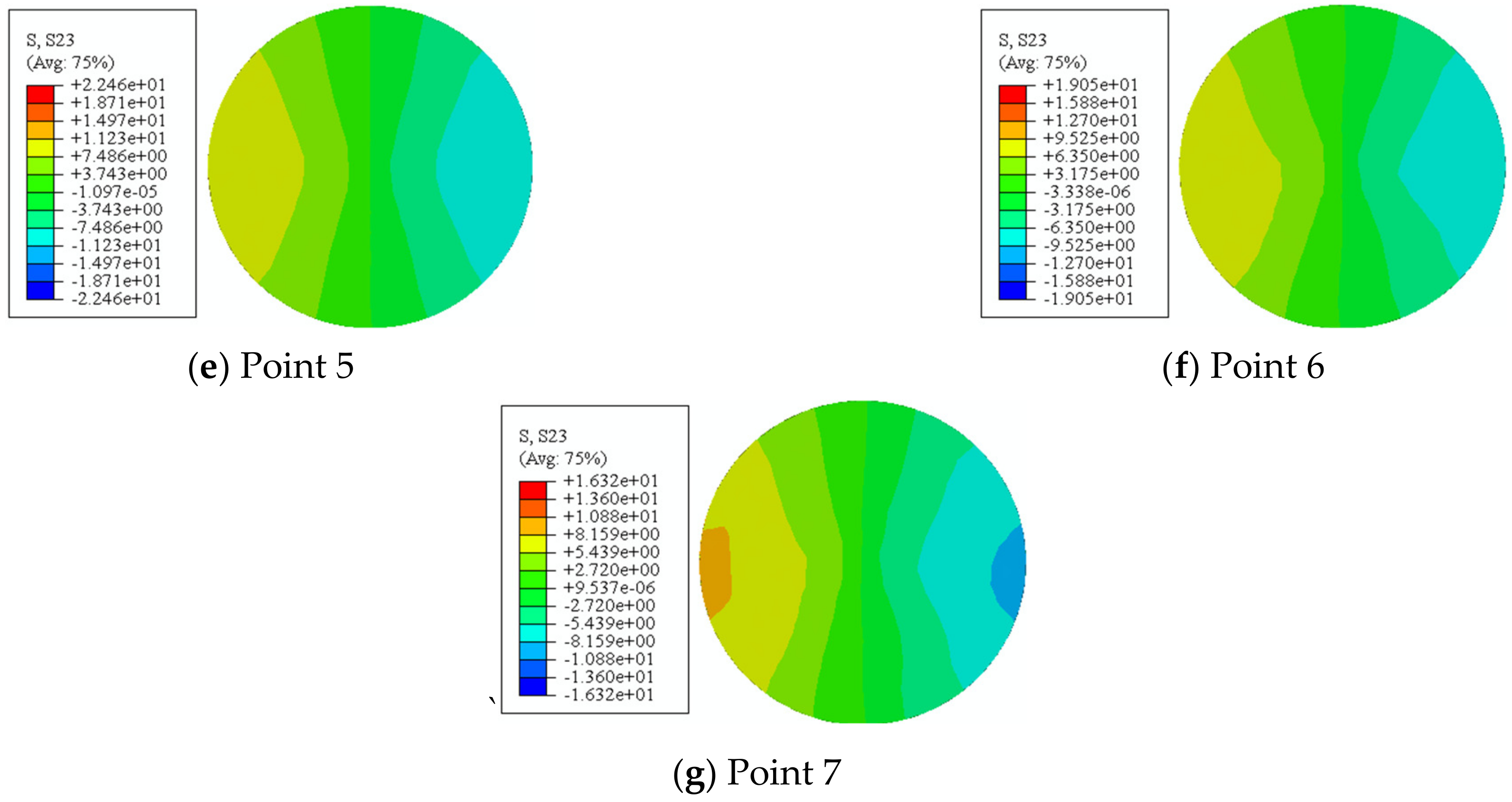
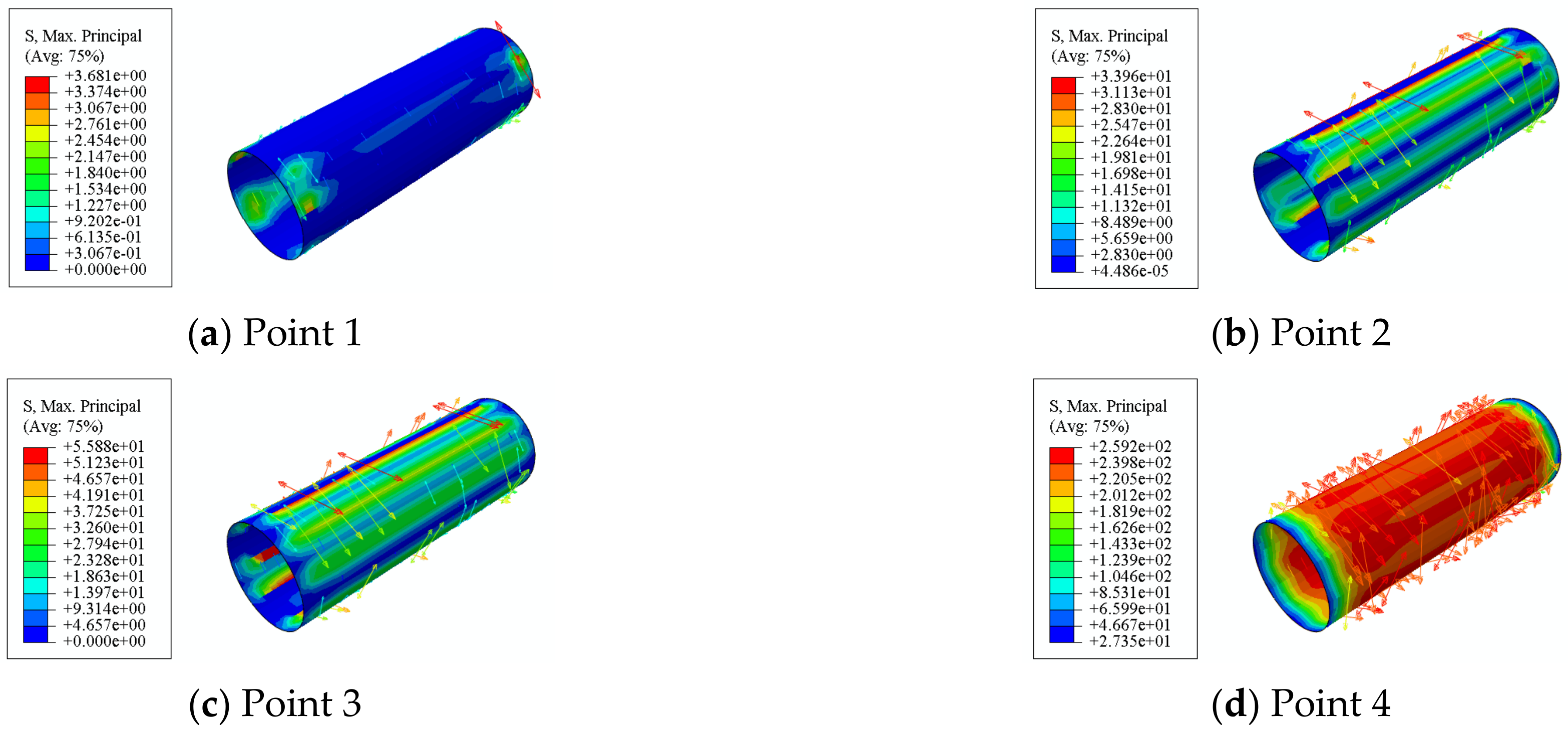
- The z-axis component τyz of the shear stress of the concrete/steel tube in the middle section of the specimen is evenly distributed along the length direction of the specimen. The maximum tensile stress of the concrete in the middle section of the circular specimen increases from inside to outside along the section radius, and the maximum tensile stress is evenly distributed along the length direction of the specimen.
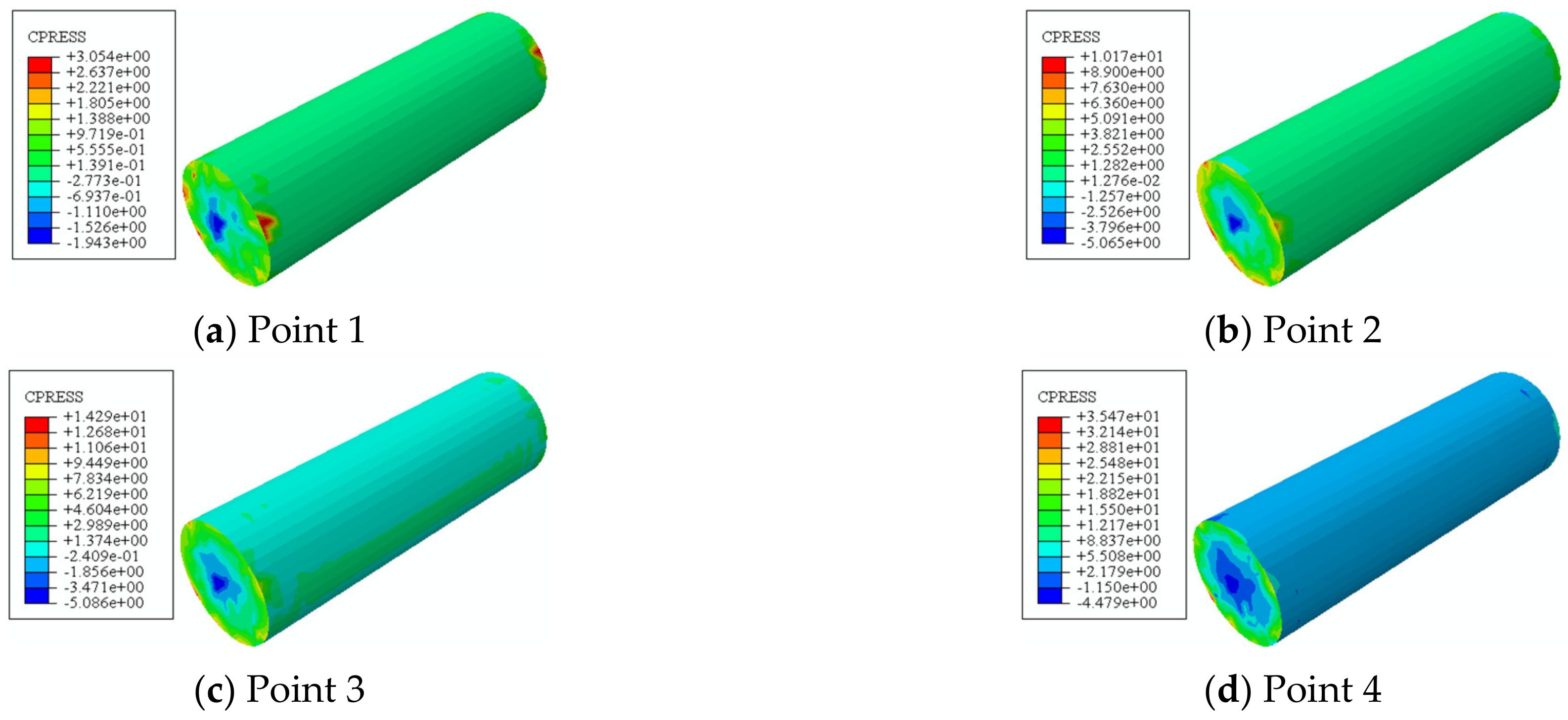
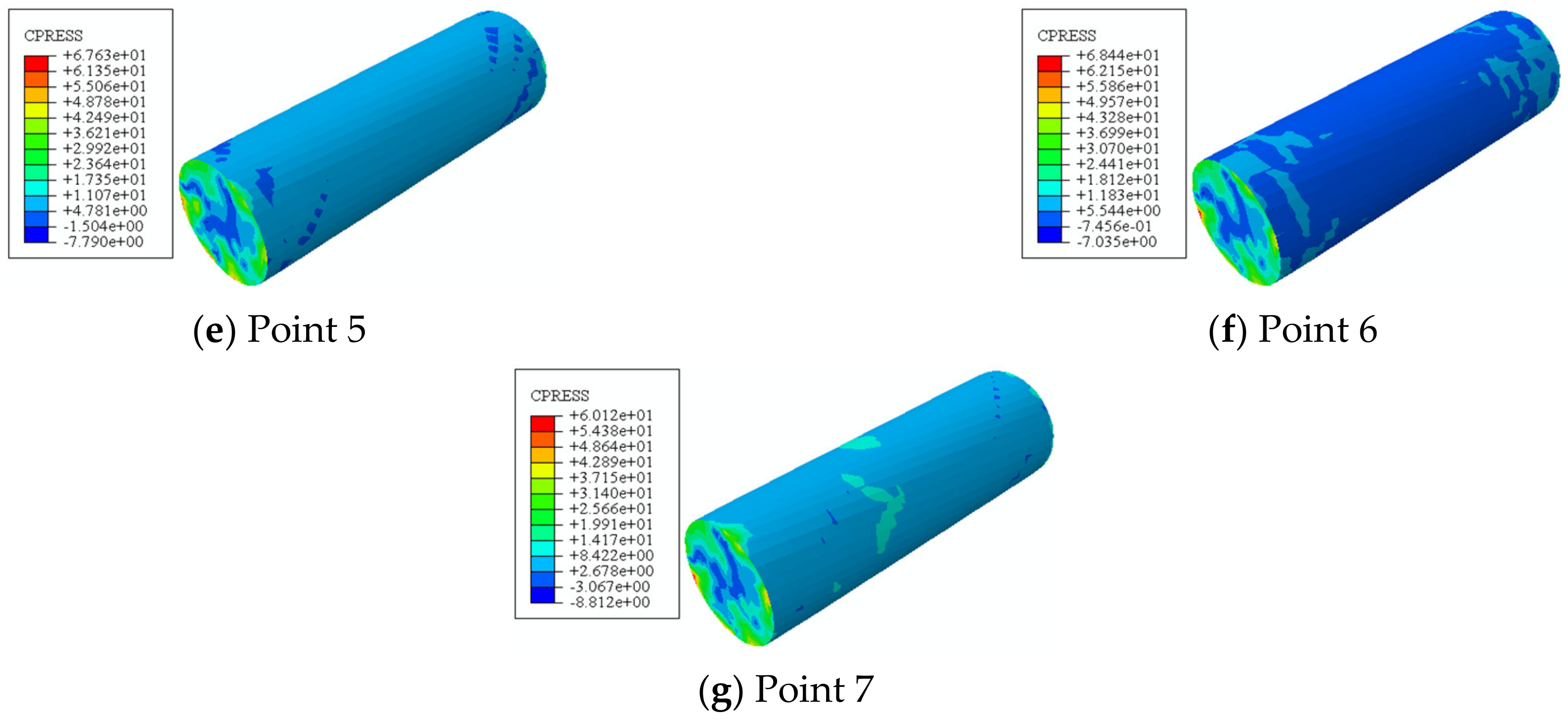
- At the initial stage of loading, the interaction force between the steel tube and concrete is small. The interaction force between the steel tube and concrete is equal in the symmetrical position of the same section, and the interaction force between the steel tube and concrete is evenly distributed along the axis.
- With the development of green buildings, it is becoming more and more important to determine whether constituent materials can be used as renewable resources after the structure reaches its service life. The concrete-filled CFRP-steel tube examined in this study is made of steel and concrete, and the steel tube and concrete in its main components could be used as reusable resources. The steel tube and concrete performance after tests will also be studied in the future.
Author Contributions
Funding
Institutional Review Board Statement
Informed Consent Statement
Data Availability Statement
Conflicts of Interest
References
- Jin, L.; Fan, L.; Li, P.; Du, X. Size effect of axial-loaded concrete-filled steel tubular columns with different confinement coefficients. Eng. Struct. 2019, 198, 109503. [Google Scholar] [CrossRef]
- Liu, Y.; Dong, Z. Experimental study on torsional behavior of circular CFRP concrete filled steel tube. J. Civ. Eng. 2009, 42, 91–101. [Google Scholar]
- Shakir, A.S.; Guan, Z.W.; Jones, S.W. Lateral impact response of the concrete filled steel tube columns with and without CFRP strengthening. Eng. Struct. 2016, 116, 148–162. [Google Scholar] [CrossRef]
- Chen, C.; Zhao, Y.H.; Zhu, C.Y.; Wei, L. Study on the impact response of concrete filled FRP-steel tube structures. Adv. Mater. Res. 2012, 368–373, 549–552. [Google Scholar] [CrossRef]
- Liu, L.; Li, X.; Wu, Y.; Cheng, Z.; Gao, Y. Numerical simulation analysis of the anti explosion performance of carbon fiber reinforced composite material confined steel tube concrete columns. Steel Struct. 2018, 33, 119–124. [Google Scholar]
- Sundarraja, M.C.; Ganesh, P.G. Investigation on strengthening of CFST members under compression using CFRP composites. J. Reinf. Plast. Compos. 2011, 30, 1251–1264. [Google Scholar] [CrossRef]
- Tao, Z.; Han, L.H.; Zhuang, J.P. Axial loading behavior of CFRP strengthened concrete-filled steel tubular stub columns. Adv. Struct. Eng. 2007, 10, 37–46. [Google Scholar] [CrossRef]
- Chellapandian, M.; Prakash, S.S.; Rajagopal, A. Analytical and Finite Element Studies on Hybrid FRP Strengthened RC Column Elements under Axial and Eccentric Compression. Compos. Struct. 2017, 184, 234–248. [Google Scholar] [CrossRef]
- Zhu, C.; Zhao, Y.; Yuan, Y.; Wang, K.; Sun, L. Local buckling FRP enhances the seismic performance of thin-walled steel tube concrete. J. Comput. Mech. 2018, 35, 552–559. [Google Scholar]
- Wang, J.; Sheng, M.; Liao, F.; Shen, Q. Bias compression performance of circular steel tube concrete short columns with void defects in carbon fiber reinforced composite spacing wrapping. Ind. Build. 2019, 49, 18. [Google Scholar]
- GB 50936-2014; National Standard of the People’s Republic of China. Technical Specification for Concrete-Filled Steel Tube Structures. China Architecture and Building Press: Beijing, China, 2014.
- Al-Mosawe, A.; Al-Mahaidi, R.; Zhao, X.L. Effect of CFRP properties, on the bond characteristics between steel and CFRP laminate under quasi-static loading. Constr. Build. Mater. 2015, 98, 489–501. [Google Scholar] [CrossRef]
- Abdel-Rahman, N.; Sivakumaran, K.S. Material properties models for analysis of cold-formed steel members. J. Struct. Eng. 1997, 123, 1135–1143. [Google Scholar] [CrossRef]
- Choi, K.K.; Xiao, Y. Analytical model of circular CFRP confined concrete-filled steel tubular columns under axial compression. J. Compos. Constr. 2020, 14, 125–133. [Google Scholar] [CrossRef]
- Nabati, A.; Ghazijahani, T.G. CFRP-reinforced circular steel tubes with cutout under axial loading. J. Constr. Steel Res. 2020, 164, 105775. [Google Scholar] [CrossRef]
- Jiang, J.F.; Wu, Y.F. Identification of material parameters for Drucker-Prager plasticity model for FRP confined circular concrete columns. Int. J. Solids Struct. 2020, 49, 445–456. [Google Scholar] [CrossRef]
- Karren, K.W. Corner properties of cold-formed steel shapes. J. Struct. Div. ASCE 1967, 93, 401–432. [Google Scholar] [CrossRef]
- Ztürk, B.; Yilmaz, C. Analytical investigation of effect of retrofit application using CFRP on seismic behavior of a monumental building at historical Cappadocia region of Turkey. In Proceedings of the 9th US National and 10th Canadian Conference on Earthquake Engineering, Toronto, ON, Canada, 25–29 July 2010; pp. 25–29. [Google Scholar]


| No. | Specimen Labels | fcu (MPa) | mt Layer(s) | ml Layer(s) | xcf | hcf | xs |
|---|---|---|---|---|---|---|---|
| 1 | CT00A | 31.5 | 0 | 0 | 1.38 | 0 | 0 |
| 2 | CT00B | 33 | 0 | 0 | 1.05 | 0 | 0 |
| 3 | CT00C | 35.2 | 0 | 0 | 0.88 | 0 | 0 |
| 4 | CT10A | 31.5 | 1 | 0 | 1.38 | 0.21 | 0 |
| 5 | CT10B | 33 | 1 | 0 | 1.05 | 0.16 | 0 |
| 6 | CT10C | 35.2 | 1 | 0 | 0.88 | 0.17 | 0 |
| 7 | CT11A | 31.5 | 1 | 1 | 1.38 | 0.21 | 0.2 |
| 8 | CT11B | 33 | 1 | 1 | 1.05 | 0.16 | 0.2 |
| 9 | CT11C | 35.2 | 1 | 1 | 0.88 | 0.17 | 0.2 |
| 10 | CT12A | 31.5 | 1 | 2 | 1.38 | 0.21 | 0.4 |
| 11 | CT12B | 33 | 1 | 2 | 1.05 | 0.16 | 0.4 |
| 12 | CT12C | 35.2 | 1 | 2 | 0.88 | 0.17 | 0.4 |
| 13 | CT20C | 35.2 | 2 | 0 | 0.88 | 0.27 | 0 |
| 14 | CT21C | 35.2 | 2 | 1 | 0.88 | 0.27 | 0.2 |
| 15 | CT22C | 35.2 | 2 | 2 | 0.88 | 0.27 | 0.4 |
| 16 | CT30C | 35.2 | 3 | 0 | 0.88 | 0.41 | 0 |
| 17 | CT31C | 35.2 | 3 | 1 | 0.88 | 0.41 | 0.2 |
| 18 | CT32C | 35.2 | 3 | 2 | 0.88 | 0.41 | 0.4 |
| fy/MPa | fu/MPa | Es/GPa | vs | ε′/% |
|---|---|---|---|---|
| 466 | 610 | 206 | 0.28 | 27 |
| No. | C | FA | S | G | W | SP |
|---|---|---|---|---|---|---|
| A | 0.6 | 0.4 | 2.5 | 1.5 | 0.4 | 0.01 |
| B | 0.6 | 0.4 | 2 | 1.4 | 0.35 | 0.01 |
| C | 0.74 | 0.26 | 1.2 | 1.5 | 0.3 | 0.009 |
| Thickness (mm) | Ecf (GPa) | ecftr (me) | ecflr (me) |
|---|---|---|---|
| 0.111 | 230 | 5500 | 7000 |
| Geometry | Steel | Concrete | CFRP | End Plate |
|---|---|---|---|---|
| Section (mm) | 120 × 120 | 98 × 98 | Different dimensions | 200 × 200 |
| Thickness (mm) | 2 | / | Different dimensions | 20 |
| Specimen length (mm) | 360 | 360 | 360 | / |
| Type of geometry | Solid | Solid | Shell | Solid |
| Mesh type | C3D8R | C3D8R | M3D4 | C3D8R |
| Type | Analytical |
|---|---|
| Test | 1. The typical T-θ curve is characterized by the elastic stage from the beginning of loading to the cracking of concrete. 2. With the fracture of the transverse CFRP, the longitudinal CFRP immediately peels off, and the T-θ curve of the specimen has an obvious steep drop section. |
| Numerical studies | 1. The simulation results are in good agreement with the experimental results. 2. At the initial stage of loading, the interaction force between the steel tube and concrete is small. The interaction force between the steel tube and concrete is equal in the symmetrical position of the same section, and the interaction force between the steel tube and concrete is evenly distributed along the axis. |
Disclaimer/Publisher’s Note: The statements, opinions and data contained in all publications are solely those of the individual author(s) and contributor(s) and not of MDPI and/or the editor(s). MDPI and/or the editor(s) disclaim responsibility for any injury to people or property resulting from any ideas, methods, instructions or products referred to in the content. |
© 2023 by the authors. Licensee MDPI, Basel, Switzerland. This article is an open access article distributed under the terms and conditions of the Creative Commons Attribution (CC BY) license (https://creativecommons.org/licenses/by/4.0/).
Share and Cite
Qing-li, W.; Hui-ying, Z.; Peng, K. Torsional Behavior of Concrete-Filled Circular Steel Tubes Strengthened with CFRP. Materials 2023, 16, 6964. https://doi.org/10.3390/ma16216964
Qing-li W, Hui-ying Z, Peng K. Torsional Behavior of Concrete-Filled Circular Steel Tubes Strengthened with CFRP. Materials. 2023; 16(21):6964. https://doi.org/10.3390/ma16216964
Chicago/Turabian StyleQing-li, Wang, Zhang Hui-ying, and Kuan Peng. 2023. "Torsional Behavior of Concrete-Filled Circular Steel Tubes Strengthened with CFRP" Materials 16, no. 21: 6964. https://doi.org/10.3390/ma16216964
APA StyleQing-li, W., Hui-ying, Z., & Peng, K. (2023). Torsional Behavior of Concrete-Filled Circular Steel Tubes Strengthened with CFRP. Materials, 16(21), 6964. https://doi.org/10.3390/ma16216964