
Recycling of Hard Disk Drive Platters via Plastic Consolidation


Abstract
:1. Introduction
2. Materials and Methods
3. Results and Discussion
4. Conclusions
Author Contributions
Funding
Institutional Review Board Statement
Informed Consent Statement
Data Availability Statement
Conflicts of Interest
References
- Chaudhary, R.; Kansal, A. A perspective on the future of the magnetic hard drive (HDD) technology. Int. J. Tech. Res. Appl. 2015, 3, 63–74. [Google Scholar]
- Khan, J.B. Chapter 45—Hard Drive Imaging, Computer and Information Security Handbook, 3rd ed.; Elsevier: Amsterdam, The Netherlands, 2017; pp. 669–672. [Google Scholar] [CrossRef]
- Osakabe, K.; Isono, H.; Iwata, K.; Eda, S.; Terada, K. Glass Substrate for Magnetic Disc and Manufacturing Method of the Same. U.S. Patent 8,119,267 B2, 21 February 2012. Available online: https://patents.google.com/patent/US8119267 (accessed on 1 June 2023).
- Critical Raw Materials for the EU, Report of the Ad-Hoc Working Group on Defining Critical Raw Metals, European Commission, June 2010. Available online: https://www.euromines.org/files/what-we-do/sustainable-development-issues/2010-report-critical-raw-materials-eu.pdf (accessed on 12 June 2023).
- Tudose, I.V.; Comanescu, F.; Pascariu, P.; Bucur, S.; Rusen, L.; Iacomi, F.; Koudoumas, E.; Suchea, M.P. Chapter 2—Chemical and physical metods for multifunctional nanostructured interface fabrication. In Functional Nanostructured Interfaces for Environmental and Biomedical Applications, Micro and Nano Technologies; Elsevier: Amsterdam, The Netherlands, 2019; pp. 15–26. [Google Scholar] [CrossRef]
- Rudnik, E.; Kozak, B.; Włoch, G. Selection of reagents for leaching of computer disc platters. Rudy Met. Nieżelazne 2017, 5, 18–22. [Google Scholar] [CrossRef]
- Microcontamination Testing Services, Cleanliness Test for Disk Drive Parts, Setsco Services Pte Ltd. Available online: https://www.setsco.com/doc/microcontamination/BROCHURE%20FOR%20DISK%20DRIVE%20TESTING%20I.pdf (accessed on 27 July 2023).
- Szałatkiewicz, J. Resources recovery from computer hard disc drives. Ecol. Eng. Environ. Technol. 2010, 23, 77–87. [Google Scholar]
- Dańczak, A.; Chojnacka, I.; Matuska, S.; Marcola, K.; Lesniewicz, A.; Wełna, M.; ŻAK, A.; Adamski, Z.; Rycerz, L. The recycling-oriented material characterization of hard disc drives with special emphasis on NdFeB magnets. Pchysicochem. Probl. Miner. Process. 2018, 54, 363–376. [Google Scholar] [CrossRef]
- München, D.D.; Veit, H.M. Neodymium as the main feature of permanent magnets from hard disk drives (HDDs). Waste Manag. 2017, 61, 372–376. [Google Scholar] [CrossRef]
- Grochowski, E. Emerging Trends in Data Storage on Magnetic Hard Disk Drives; IBM Almaden Research Center: San Jose, CA, USA, 2013; Available online: https://courses.cs.washington.edu/courses/cse590s/03au/grochowski-trends.pdf (accessed on 15 June 2023).
- München, D.D.; Stein, R.T.; Veit, H.M. Rare Earth Elements Recycling Potential Estimate Based on End-of-Life NdFeB Permanent Magnets from Mobile Phones and Hard Disk Drives in Brazil. Minerals 2021, 11, 1190. [Google Scholar] [CrossRef]
- Aluminum Alloy Substrates for Magnetic Disks, Aluminum Lightens the World, UACJ. Available online: https://www.uacj.co.jp/english/products/sheeting/aas-magnetic.htm.website (accessed on 27 July 2023).
- de Assunção, M.D.; Lefèvre, L. Chapter Four—State of the Art on Technology and Practices for Improving the Energy Efficiency of Data Storage. Adv. Comput. 2012, 87, 89–124. [Google Scholar] [CrossRef]
- Directive 2012/19/EU of the European Parliament and of the Council, Official Journal of the European Union. Available online: https://eur-lex.europa.eu/LexUriServ/LexUriServ.do?uri=OJ:L:2012:197:0038:0071:EN:PDF (accessed on 12 July 2012).
- Waste Electrical and Electronic Equipment Recycling (WEEE). Health and Safety Executive. Available online: https://www.hse.gov.uk/waste/waste-electrical.htm (accessed on 27 July 2023).
- Firdaus, M.; Rhamdhani, M.A.; Durandet, Y.; Rankin, W.J.; McGregor, K. Review of High-Temperature Recovery of Rare Earth (Nd/Dy) from Magnet Waste. J. Sustain. Metall. 2016, 2, 276–295. [Google Scholar] [CrossRef]
- Sprecher, B.; Kleijn, R.; Kramer, J. Recycling Potential of Neodymium: The Case of Computer Hard Disk Drives. Environ. Sci. Technol. 2014, 48, 9506–9513. [Google Scholar] [CrossRef]
- Klemettinen, A.; Żak, A.; Chojnacka, I.; Matuska, S.; Lesniewicz, A.; Wełna, M.; Adamski, Z.; Klemettinen, L.; Rycerz, L. Leaching of Rare Earth Elements from NdFeB Magnets without Mechanical Pretreatment by Sulfuric (H2SO4) and Hydrochloric (HCl) Acids. Minerals 2021, 11, 1374. [Google Scholar] [CrossRef]
- Yoon, H.-S.; Kim, C.-J.; Chung, K.W.; Lee, S.-J.; Joe, A.-R.; Shin, Y.-H.; Lee, A.-I.; Yoo, S.-J.; Kim, J.-G. Leaching kinetics of neodymium in sulfuric acid from E-scrap of NdFeB permanent magnet. Korean J. Chem. Eng. 2014, 31, 706–711. [Google Scholar] [CrossRef]
- Uysal, E.; Al, S.; Emil-Kaya, E.; Stopic, S.; Gürmen, S.; Friedrich, B. Hydrometallurgical recycling of waste NdFeB magnets: Design of experiment, optimisation of low concentrations of sulphuric acid leaching and process analysis. Can. J. Metall. Mater. Sci. 2023, 62, 107–118. [Google Scholar] [CrossRef]
- Reisdörfer, G.; Bertuol, D.; Tanabe, E.H. Recovery of neodymium from the magnets of hard disk drives using organic acids. Miner. Eng. 2019, 143, 105938. [Google Scholar] [CrossRef]
- Tian, Y.; Liu, Z.; Zhang, G. Recovering REEs from NdFeB wastes with high purity and efficiency by leaching and selective precipitation process with modified agents. J. Rare Earths 2019, 37, 205–210. [Google Scholar] [CrossRef]
- Allahkarami, E.; Rezai, B.; Bozorgmehr, M.; Adib, A. Extraction of neodymium(III) from aqueous solutions by solvent extraction with Cyanex® 572. Physicochem. Probl. Miner. Process. 2021, 57, 127–135. [Google Scholar] [CrossRef]
- Michalski, B.; Szymanski, M.; Gola, K.; Zygmuntowicz, J.; Leonowicz, M. Experimental evidence for the suitability of the hydrogen decomposition process for the recycling of Nd-Fe-B sintered magnets. J. Magn. Magn. Mater. 2022, 548, 168879. [Google Scholar] [CrossRef]
- Walton, A.; Yi, H.; Rowson, N.A.; Speight, J.D.; Mann, V.S.J.; Sheridan, R.S.; Bradshaw, A.; Harris, J.R.; Williams, A.J. The use of hydrogen to separate and recycle neodymium–iron–boron-type magnets from electronic waste. J. Clean. Prod. 2015, 104, 236–241. [Google Scholar] [CrossRef]
- Green, J.A.S. Aluminum Recycling and Processing for Energy Conservation and Sustainability; ASM International: Clevlend, OH, Canada, 2007. [Google Scholar]
- Noga, P.; Piotrowicz, A.; Skrzekut, T.; Zwoliński, A.; Strzępek, P. Effect of various forms of aluminum 6082 on the mechanical properties, microstructure and surface modification of the profile after extrusion process. Materials 2021, 14, 5066. [Google Scholar] [CrossRef]
- Korbel, A.; Bochniak, W.; Śliwa, R.; Ostachowski, P.; Łagoda, P.; Kusion, Z.; Trzebuniak, B. Low-temperature consolidation of machining chips from hardly-deformable aluminium alloys. Met. Form. 2016, XXVII, 133–152. [Google Scholar]
- Skrzekut, T.; Kula, A.; Blaz, L. Effect of annealing temperature on the structure of mechanically alloyed Al-AgO composite. In Proceedings of the METAL 2015—24th International Conference on Metallurgy and Materials, Conference Proceedings, Brno, Czech Republic, 3–5 June 2015; pp. 1639–1643. [Google Scholar]
- Wloch, G.; Skrzekut, T.; Sobota, J.; Woźnicki, A.; Cisoń, J. The structure and mechanical properties of plastically consolidated Al-Ni alloy. Key Eng. Mater. 2016, 682, 245–251. [Google Scholar] [CrossRef]
- Dybiec, H. Plastic consolidation of metallic powders. Arch. Metall. Mater. 2007, 52, 161–170. [Google Scholar]
- Skrzekut, T.; Kula, A.; Blaz, L. Structure evolution in annealed and hot deformed AlMg-CeO2 composite. Key Eng. Mater. 2016, 682, 259–264. [Google Scholar] [CrossRef]
- Jaworska, L.; Skrzekut, T.; Stepień, M.; Pałka, P.; Boczkal, G.; Zwoliński, A.; Noga, P.; Podsiadło, M.; Wnuk, R.; Ostachowski, P. The Pressure Compaction of Zr-Nb Powder Mixtures and Selected Properties of Sintered and KOBO-Extruded Zr-xNb Materials. Materials 2021, 14, 3172. [Google Scholar] [CrossRef]
- Wędrychowicz, M.; Wzorek, Ł.; Tokarski, T.; Noga, P.; Wiewióra, J. Recycling without melting: An alternative approach to aluminum scrap recovery. Key Eng. Mater. 2016, 682, 284–289. [Google Scholar] [CrossRef]
- Noga, P.; Skrzekut, T.; Wedrychowicz, M. Microstructure and Mechanical Properties of Al-Si Alloys Produced by Rapid Solidification and Hot Extrusion. Materials 2023, 16, 5223. [Google Scholar] [CrossRef]
- Chmura, W.; Gronostajski, J. Mechanical and tribological properties of aluminium-base composites produced by the recycling of chips. J. Mater. Process. Technol. 2000, 106, 23–27. [Google Scholar] [CrossRef]
- Tanvar, H.; Barnwal, A.; Dhawan, N. Characterization and evaluation of discarded hard disc drives for recovery of copper and rare earth values. J. Clean. Prod. 2020, 249, 119377. [Google Scholar] [CrossRef]
- PN-EN ISO 6892-1:2020-05; Metals—Tensile Test—Room Temperature Test Method. Polish Committee for Standardization: Warsaw, Poland, 2020.
- Piątkowski, J. Development of the fundamentals of melting and casting technology of Al-Me (Cr, Ni, Mo, W, Ti) master alloys used for modification of microstructure in silumins. Arch. Foundry Eng. 2009, 9, 17–20. [Google Scholar]
- Hansen, M.; Anderko, K. Constitution of Binary Alloys, 2nd ed.; McGraw-Hill Companies, Inc.: New York, NY, USA, 1958. [Google Scholar]
- Martínez-Villalobos, M.A.; Figueroa, I.A.; Suarez, M.A.; Rodríguez, G.Á.L.; Peralta, O.N.; Reyes, G.G.; López, I.A.; Martínez, J.V.; Trujillo, C.C. Microstructural Evolution of Rapid Solidified Al-Ni Alloys. J. Mex. Chem. Soc. 2016, 60, 67–72. [Google Scholar] [CrossRef]
- Lopez, G.A.; Sommadossi, S.; Gust, W.; Mittemeijer, E.J.; Zieba, P. Phase Characterization of Diffusion Soldered Ni/Al/Ni Interconnections. Interface Sci. 2002, 10, 13–19. [Google Scholar] [CrossRef]
- Franklin, S.V.; Mertens, F.; Marder, M. Portevin-Le Chatelier effect. Phys. Rev. E 2000, 62, 8195–8206. [Google Scholar] [CrossRef]
- Korbel, A. The structural aspect of the portevin-le chatelier effect in alpha brass. Scr. Metall. 1974, 8, 609–612. [Google Scholar] [CrossRef]
- Cottrell, A.H. A note on the Portevin-Le Chatelier effect. Philos. Mag. 1953, 42, 829–832. [Google Scholar] [CrossRef]
- Dybiec, H. The strain rate sensitivity during serrated yielding. Scr. Metall. 1988, 22, 595–599. [Google Scholar] [CrossRef]
- Abbadi, M.; Hähner, P.; Zeghloul, A. On the characteristics of Portevin–Le Chatelier bands in aluminum alloy 5182 under stress-controlled and strain-controlled tensile testing. Mater. Sci. Eng. A 2002, 337, 194–201. [Google Scholar] [CrossRef]
- Zdunek, J.; Spychalski, W.L.; Mizera, J.; Kurzydłowski, K.J. The influence of specimens geometry on the PLC effect in Al–Mg–Mn (5182) alloy. Mater. Charact. 2007, 58, 46–50. [Google Scholar] [CrossRef]
- Maj, P.; Zdunek, J.; Mizera, J.; Kurzydłowski, K.J. The effect of a notch on the Portevin–Le Chatelier phenomena in an Al–3Mg model alloy. Mater. Charact. 2014, 96, 46–53. [Google Scholar] [CrossRef]
- PN-EN 485-2+A1:2018-12; Aluminium and Aluminium Alloys—Sheet, Tape, Plate—Part 2: Mechanical Properties. Polish Committee for Standardization: Warsaw, Poland, 2018.
- Noga, P.; Tuz, L.; Żaba, K.; Zwoliński, A. Analysis of Microstructure and Mechanical Properties of AlSi11 after Chip Recycling, Co-Extrusion, and Arc Welding. Materials 2021, 14, 3124. [Google Scholar] [CrossRef]
- Zasadzińska, M.; Strzępek, P.; Mamala, A.; Noga, P. Reinforcement of Aluminium-Matrix Composites with Glass Fibre by Metallurgical Synthesis. Materials 2020, 13, 5441. [Google Scholar] [CrossRef]
- Samuel, M. A new technique for recycling aluminium scrap. J. Mater. Process. Technol. 2003, 135, 117–124. [Google Scholar] [CrossRef]
- U.S. Eeergy Requirements for Aluminum Production. Historical Perspective, Theoretical Limits and Current Practices; Prepared for Industrial Technologies Program Energy Efficiency and Renewable Energy; U.S. Department of Energy: Washington, DC, USA, 2007.

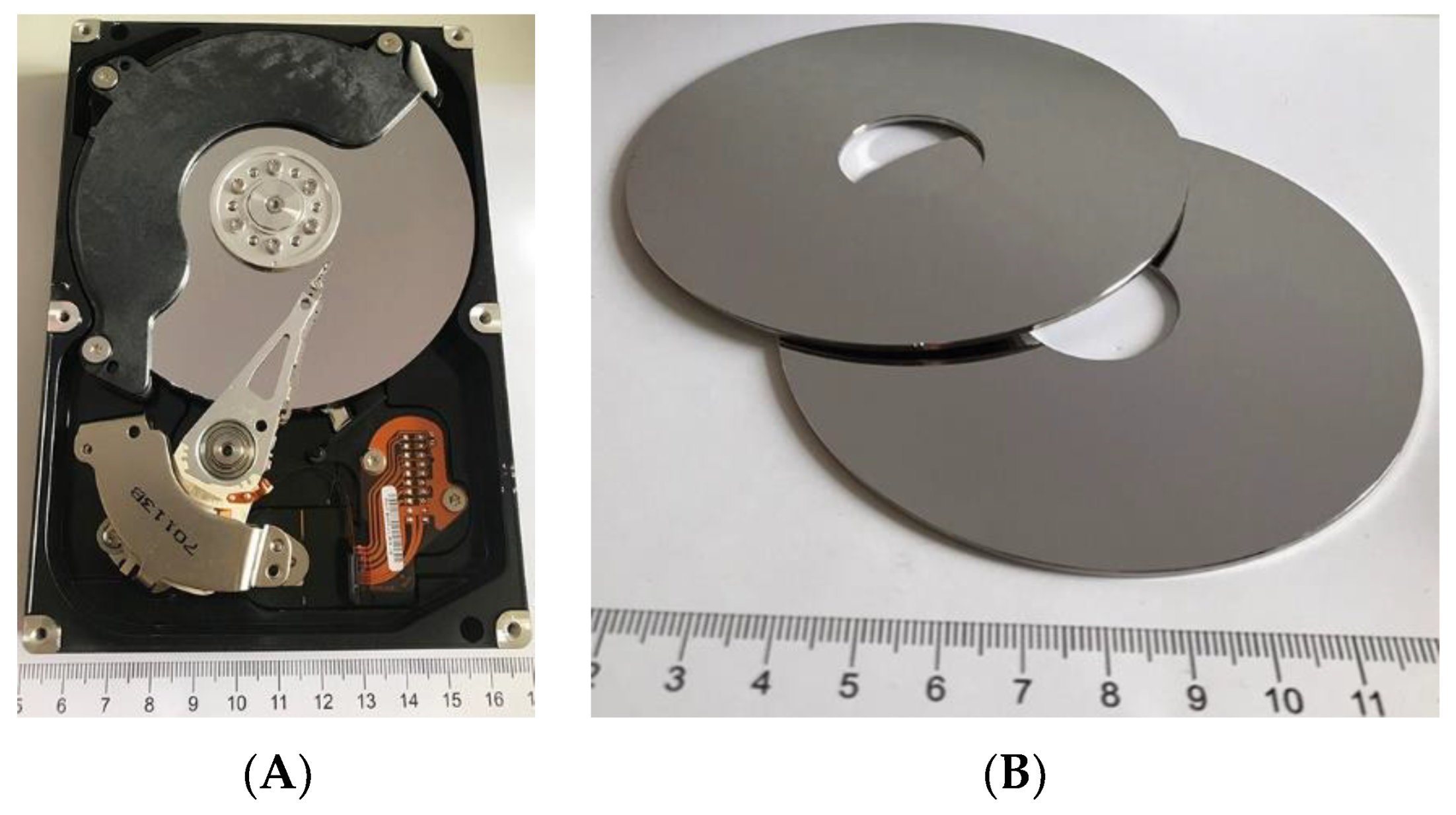
| Raw Material | The Average Mass (g) and Percentage (%) | |
|---|---|---|
| Aluminum | 264 | 51.3 |
| Ferromagnetic materials | 90 | 17.5 |
| Stainless steel | 53 | 10.4 |
| Electronics | 41 | 7.9 |
| Sub-assemblies and others | 66 | 12.9 |
| Total | 515 | 100 |
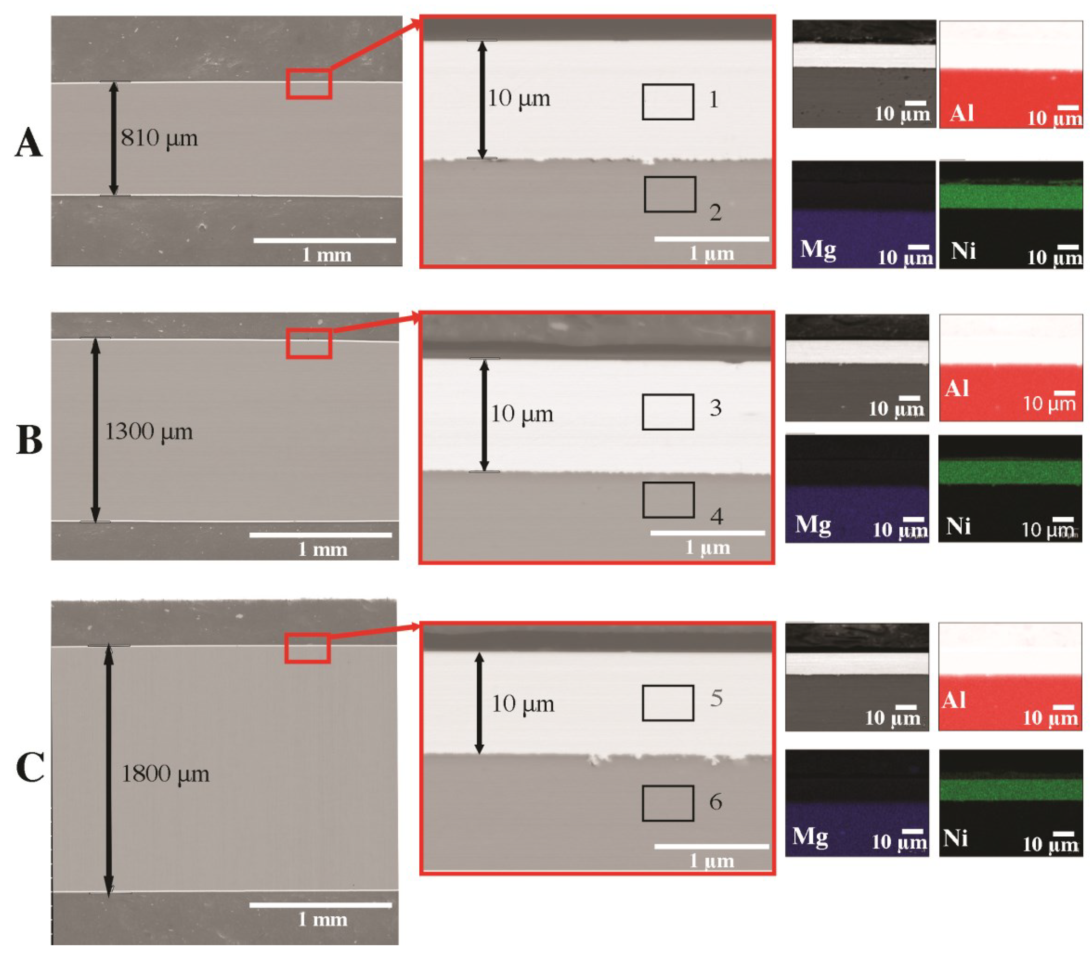
| No | Mg | Al | Ni | Fe |
|---|---|---|---|---|
| 1 | 0.0 | 0.1 | 99.9 | 0.0 |
| 2 | 4.1 | 95.8 | 0.0 | 0.1 |
| 3 | 0.0 | 0.1 | 99.9 | 0.0 |
| 4 | 4.2 | 95.7 | 0.0 | 0.1 |
| 5 | 0.0 | 0.1 | 99.9 | 0.0 |
| 6 | 4.1 | 95.7 | 0.0 | 0.1 |
| Element | Al | Ni | Fe | Mg | Other |
|---|---|---|---|---|---|
| A | 91.49 | 4.53 | 0.08 | 3.79 | 0.11 |
| B | 91.38 | 4.56 | 0.08 | 3.88 | 0.10 |
| C | 91.32 | 4.57 | 0.09 | 3.90 | 0.12 |
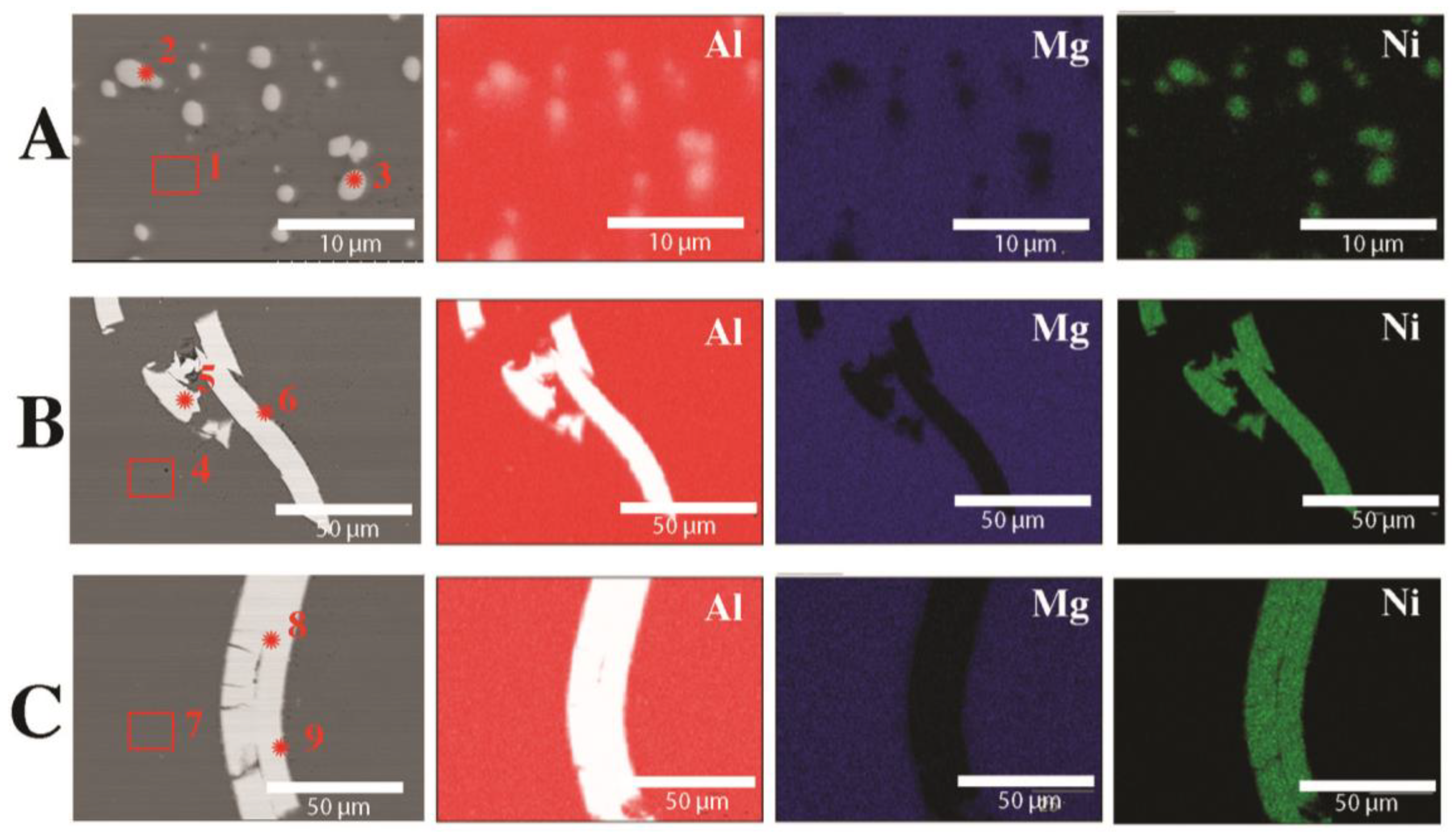
| Element | Mg | Al | Ni | Fe |
|---|---|---|---|---|
| 1 | 3.8 | 95.9 | 0.3 | 0.1 |
| 2 | 0.2 | 61.4 | 38.4 | 0.0 |
| 3 | 0.3 | 61.5 | 38.2 | 0.0 |
| 4 | 3.9 | 95.8 | 0.3 | 0.1 |
| 5 | 0.0 | 0.2 | 99.8 | 0.0 |
| 6 | 0.1 | 58.9 | 41 | 0.0 |
| 7 | 3.8 | 95.9 | 0.3 | 0.1 |
| 8 | 0.0 | 0.1 | 99.9 | 0.0 |
| 9 | 0.1 | 63.4 | 36.5 | 0.0 |
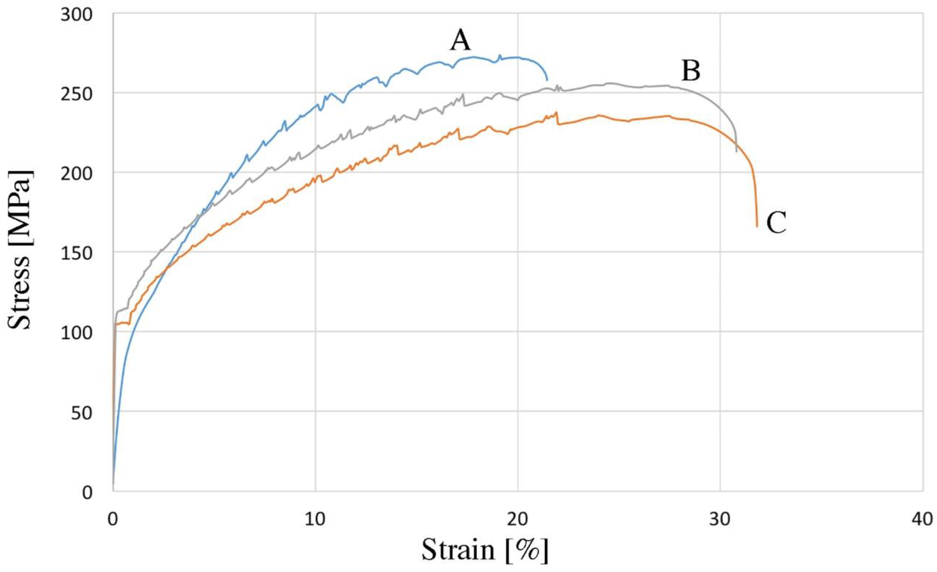
| Element | UTS, MPa | YS, MPa | Sharp Yield Point | Elongation, % | Hardness, HV2 | Density g/cm3 | |||||||
|---|---|---|---|---|---|---|---|---|---|---|---|---|---|
| LYP, MPa | UYP, MPa | ||||||||||||
| A | 271 | ±4.2 | 95 | ±4.1 | - | - | - | - | 20 | ±3.2 | 74 | ±2.2 | 2.76 |
| B | 254 | ±3.1 | - | - | 112 | ±3.3 | 116 | ±3.4 | 31 | ±3.0 | 72 | ±2.1 | 2.75 |
| C | 237 | ±2.9 | - | - | 104 | ±2.4 | 106 | ±3.0 | 32 | ±2.7 | 71 | ±1.9 | 2.75 |
Disclaimer/Publisher’s Note: The statements, opinions and data contained in all publications are solely those of the individual author(s) and contributor(s) and not of MDPI and/or the editor(s). MDPI and/or the editor(s) disclaim responsibility for any injury to people or property resulting from any ideas, methods, instructions or products referred to in the content. |
© 2023 by the authors. Licensee MDPI, Basel, Switzerland. This article is an open access article distributed under the terms and conditions of the Creative Commons Attribution (CC BY) license (https://creativecommons.org/licenses/by/4.0/).
Share and Cite
Skrzekut, T.; Wędrychowicz, M.; Piotrowicz, A. Recycling of Hard Disk Drive Platters via Plastic Consolidation. Materials 2023, 16, 6745. https://doi.org/10.3390/ma16206745
Skrzekut T, Wędrychowicz M, Piotrowicz A. Recycling of Hard Disk Drive Platters via Plastic Consolidation. Materials. 2023; 16(20):6745. https://doi.org/10.3390/ma16206745
Chicago/Turabian StyleSkrzekut, Tomasz, Maciej Wędrychowicz, and Andrzej Piotrowicz. 2023. "Recycling of Hard Disk Drive Platters via Plastic Consolidation" Materials 16, no. 20: 6745. https://doi.org/10.3390/ma16206745
APA StyleSkrzekut, T., Wędrychowicz, M., & Piotrowicz, A. (2023). Recycling of Hard Disk Drive Platters via Plastic Consolidation. Materials, 16(20), 6745. https://doi.org/10.3390/ma16206745