
Analysis of Incremental Sheet Forming of Aluminum Alloy


Abstract
:1. Introduction
- -
- -
- -
- Multi-point incremental forming (flexible 3D manufacturing process)—used for big sheets and has two opposed hard dice (lower and upper) with systems consisting of multiple punches with the highly precise movements that are necessary to obtain the desired shape being carried out with linear actuators [10,11,12];
- -
- -
- -
- -
- forming force—There are three types of forces that contribute to sheet deformation: those derived through prediction, analysis, and experimentation. Finally, the forming force shifts when different inputs are used [27];
- -
- -
- surface roughness—The tool radius, the initial roughness of the active part of the tool, the thickness of the sheet, the flow rate, the incremental depth, and the various tool designs are all process characteristics that might affect surface roughness [29];
- -
- spring back—There are two types of spring back: local and global. The first one produces poor accuracy, and the second produces residual stresses [30];
- -
- failure to fracture—During the process of sheet material deformation, it undergoes multiple stages that ultimately lead to the fracture stage [31].
2. Materials and Methods
2.1. Materials
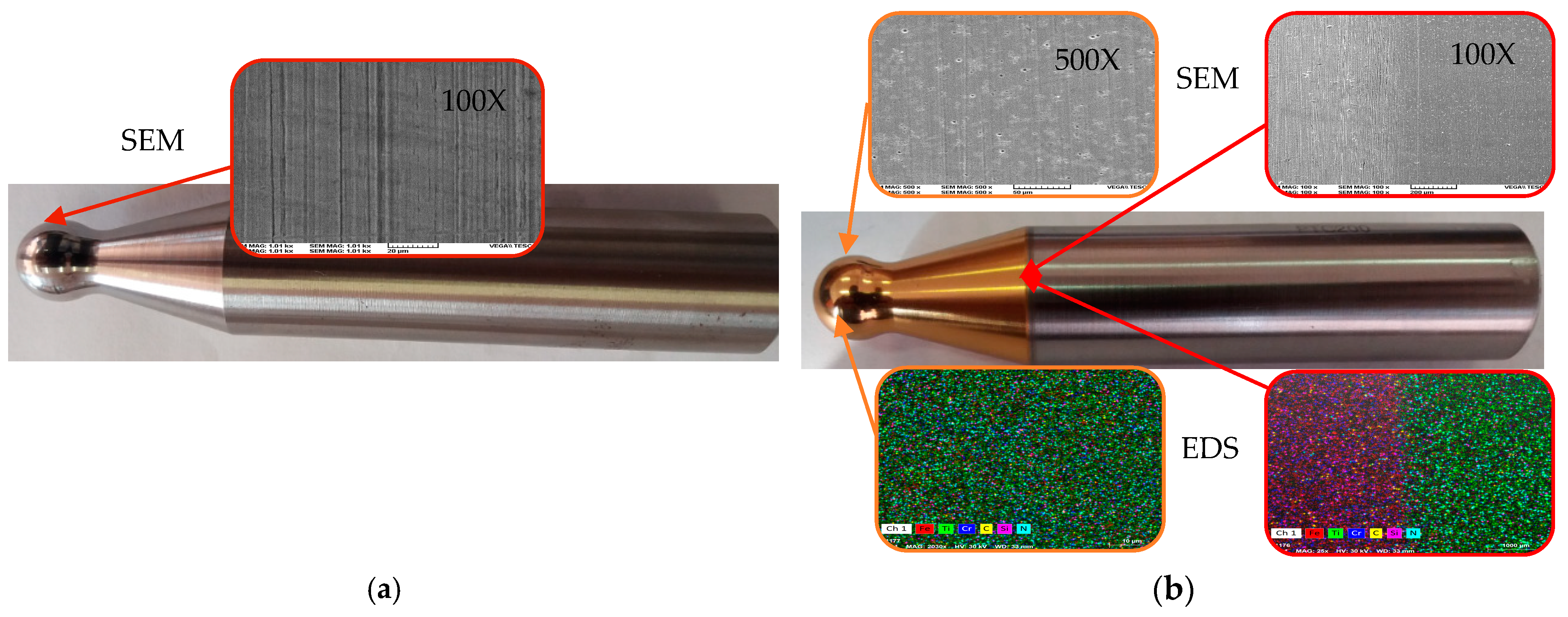
2.2. Machine Tools, Equipment, and Tools
- ✓
- Kuka KR210-2 6-axis robot, developing a maximum load of 2100 N with a positioning repeatability of ±0.06 mm. It is equipped with a KR C2 controller (KUKA Roboter GmbH, Augsburg, Germany), and the numerical programming software is SprutCam (X version, SprutCAM Tech, Limassol, Cyprus) [96,97]. This robot, together with the Aramis measurement system, was used for measuring deformations and wall thinning;
- ✓
- Incremental forming force measurement device. A measuring system, consisting of the PCB261A13 sensor (PCB Piezotronics, Inc., NY, USA), the CMD600 signal amplifier (KUKA Roboter GmbH, Augsburg, Germany), and the Quantum X MX840B acquisition system (Hottinger Brüel & Kjær, Naerum, Denmark), was used to measure the forces during the incremental forming process. The force sensor makes it possible to acquire forces in dynamic and quasi-static format, and the amplifier creates the signal voltages required for acquisition with the Quantum X system. The force transducer consists of a piezoelectric sensor assembled between 2 plates.
2.3. Methods
3. Results
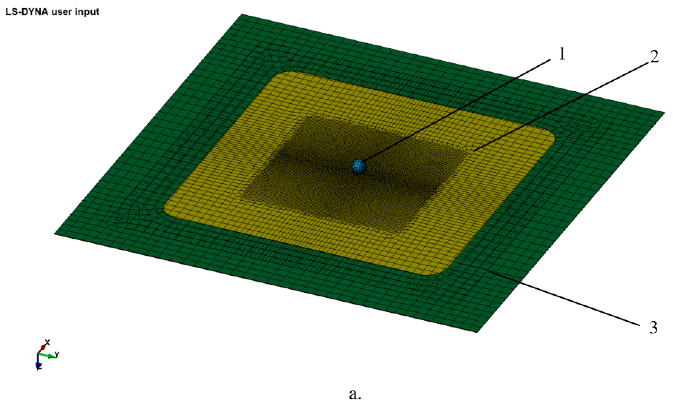
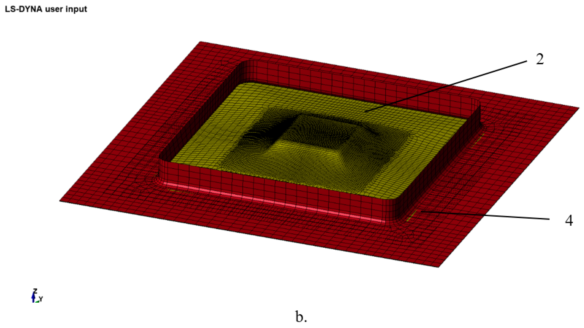
3.1. Numerical Simulation of the Variation in the Components of the Ambulation Force
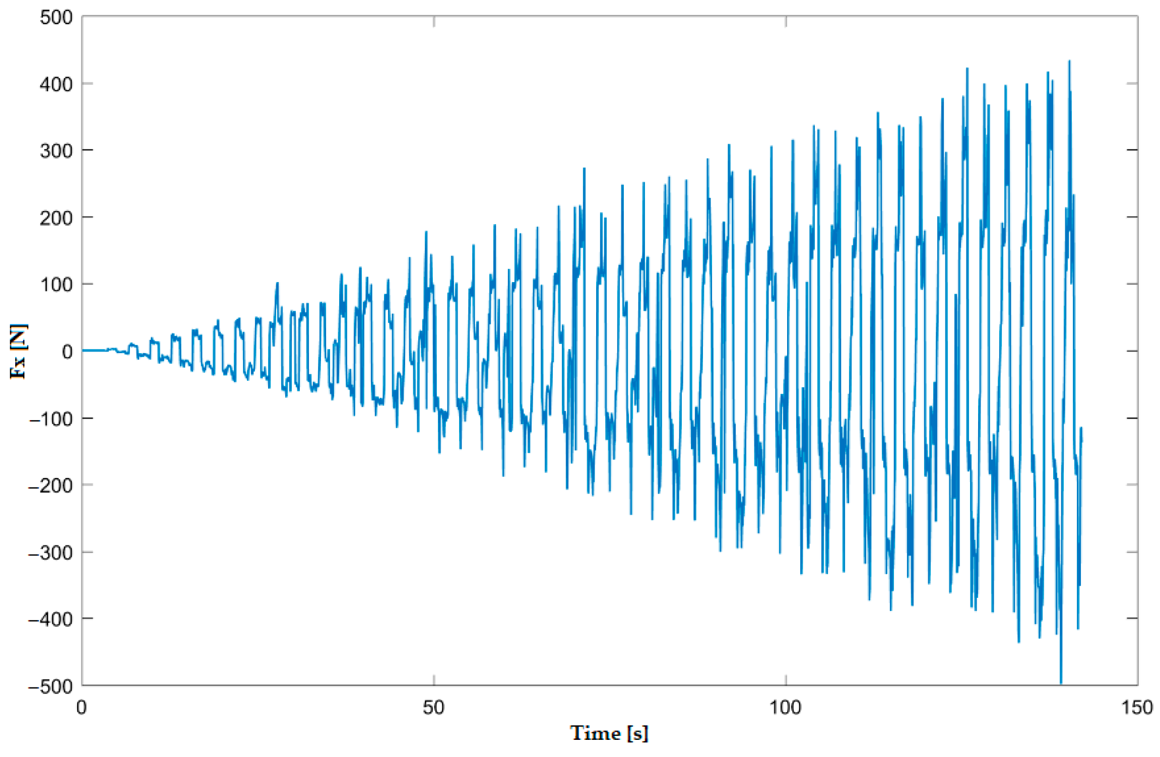
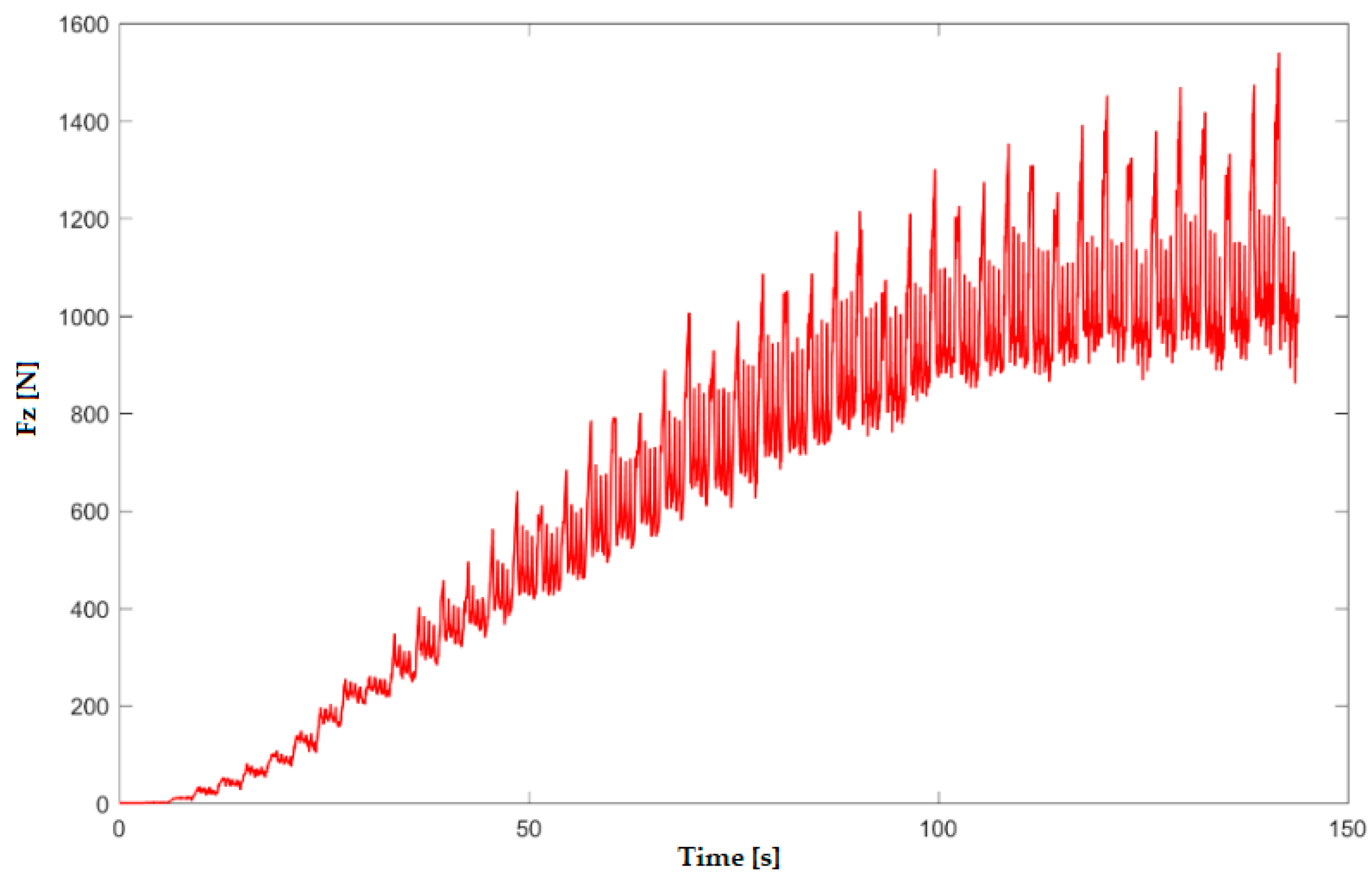
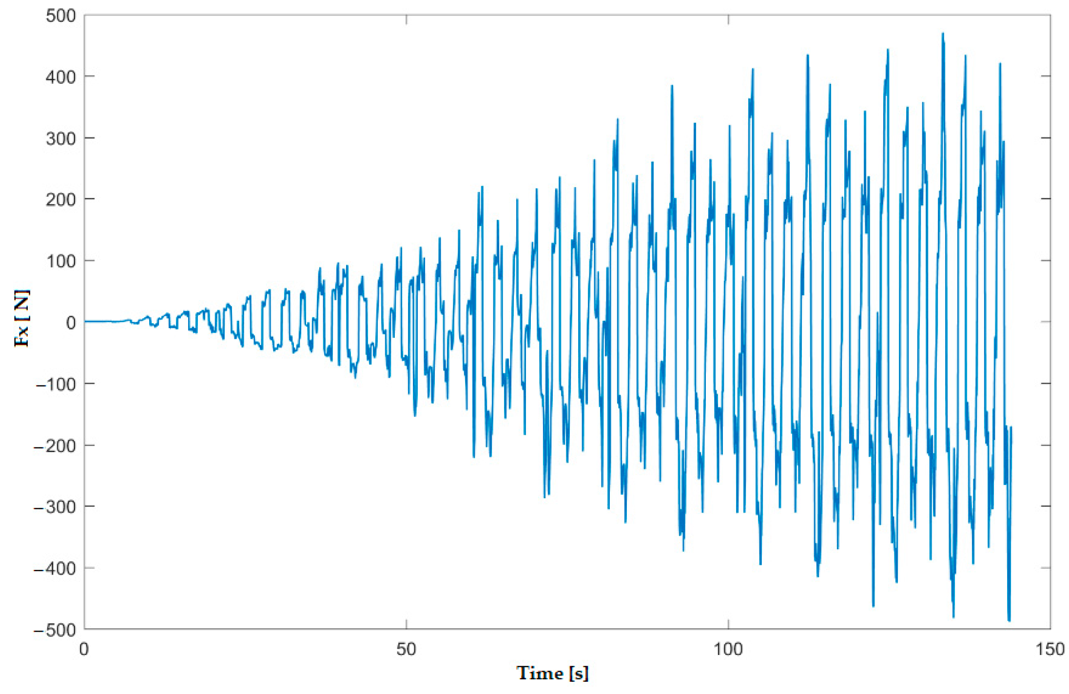
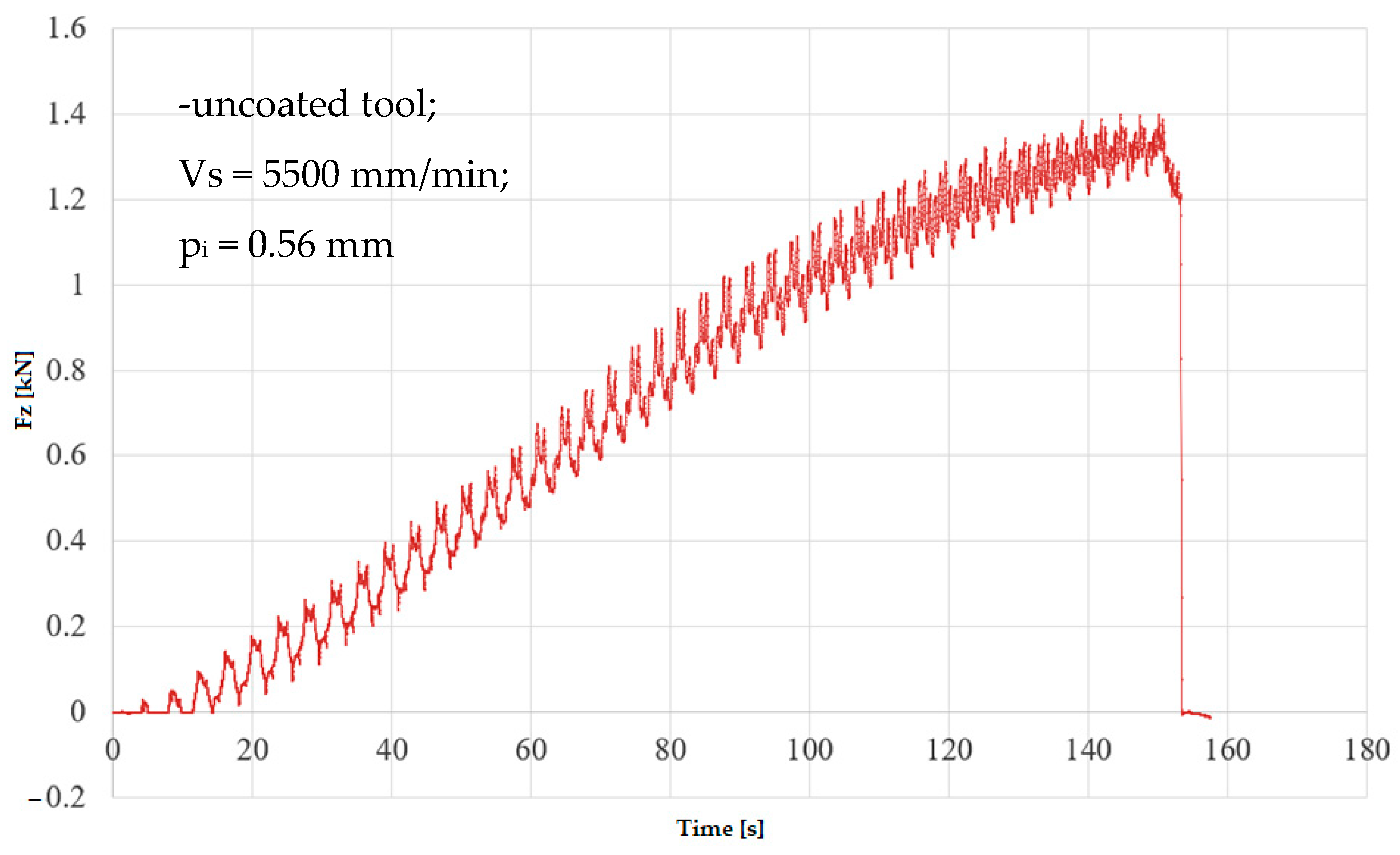
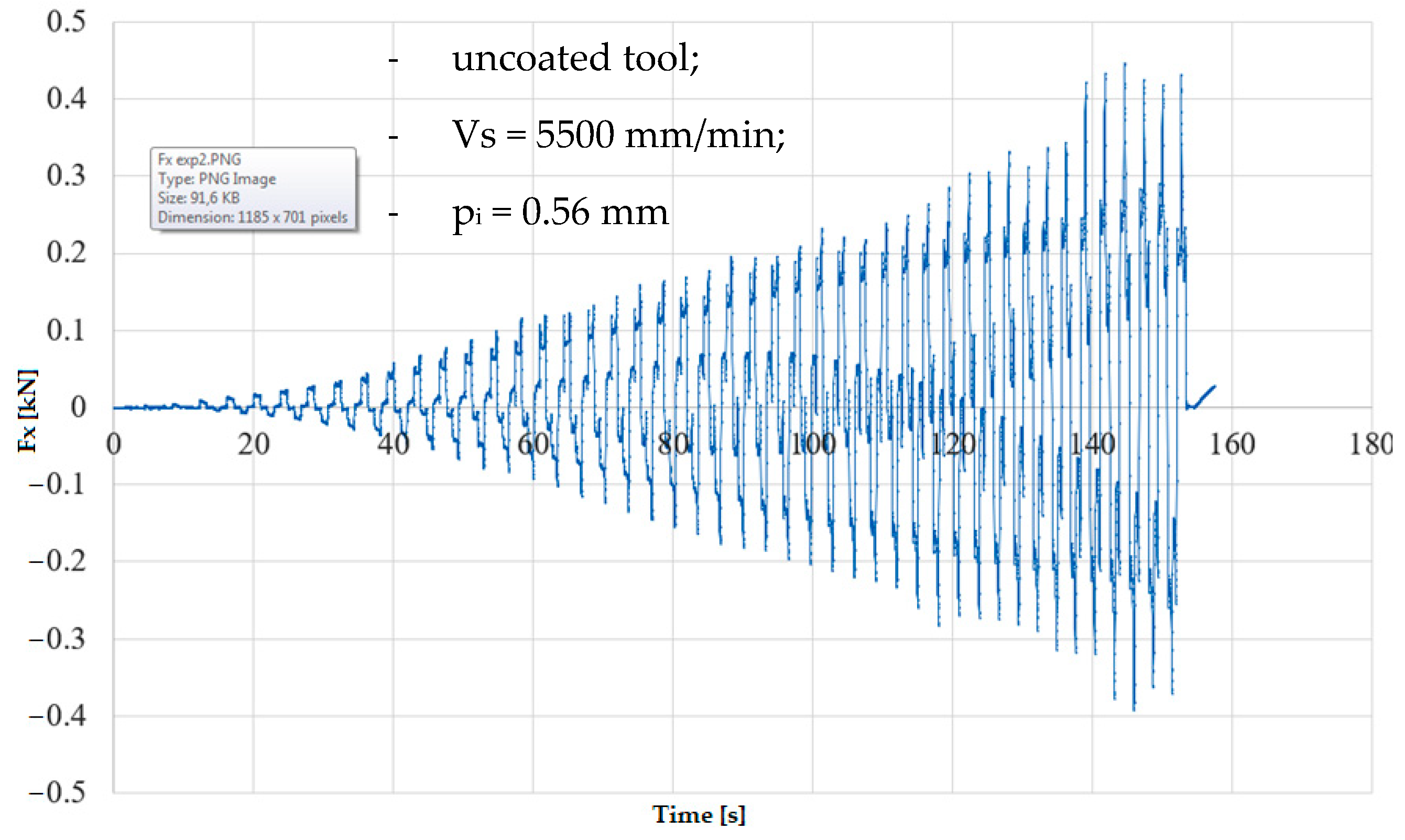
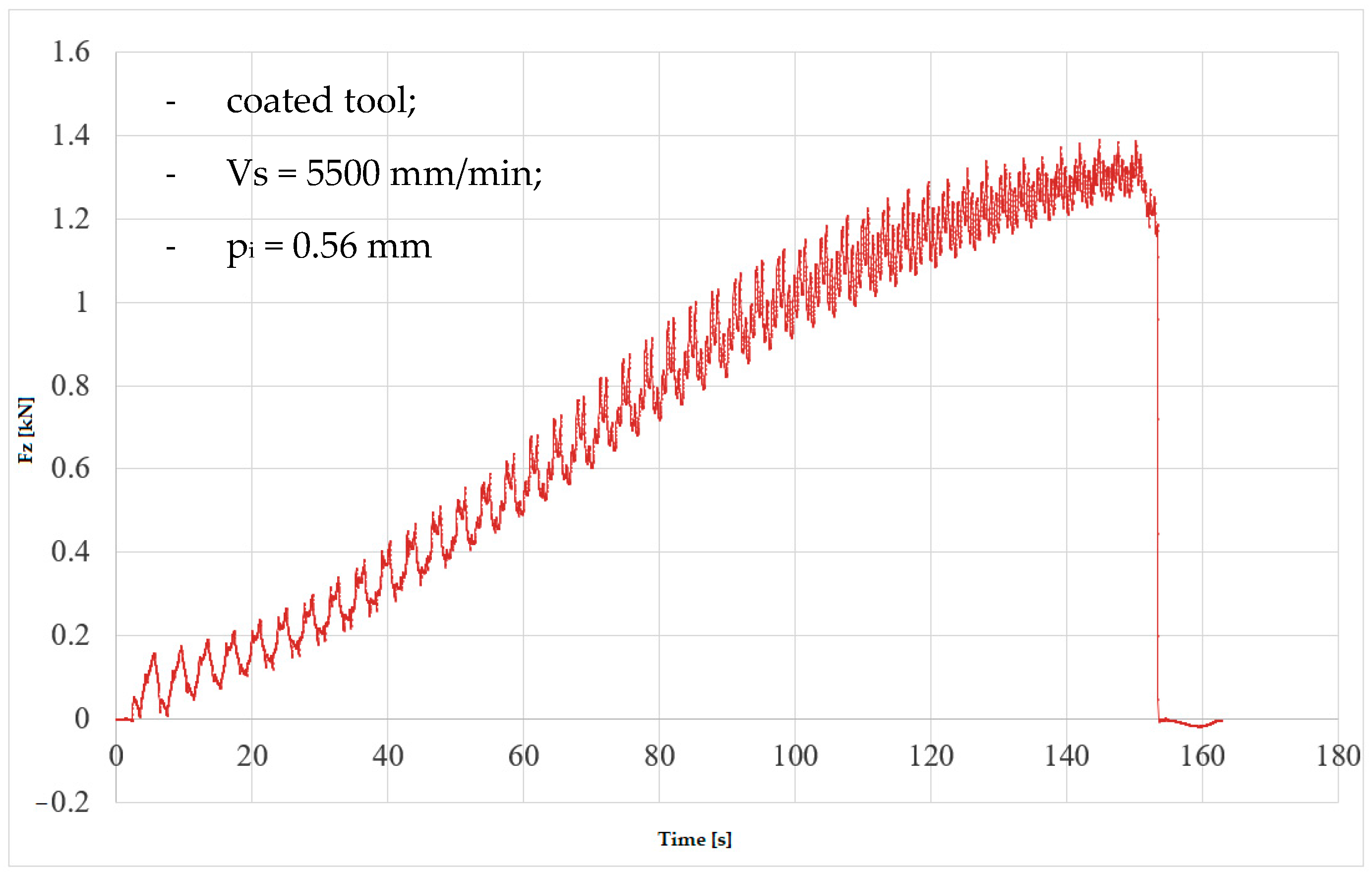
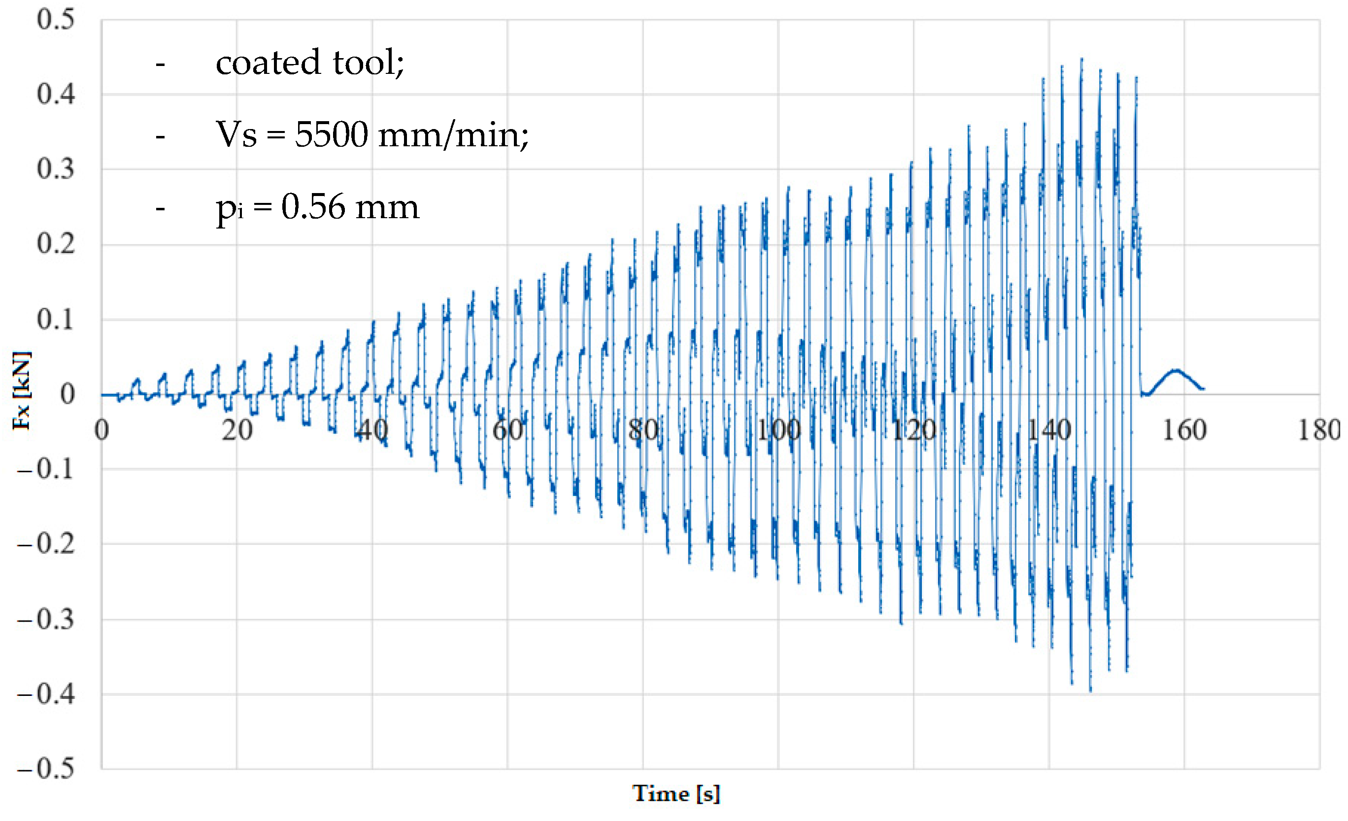
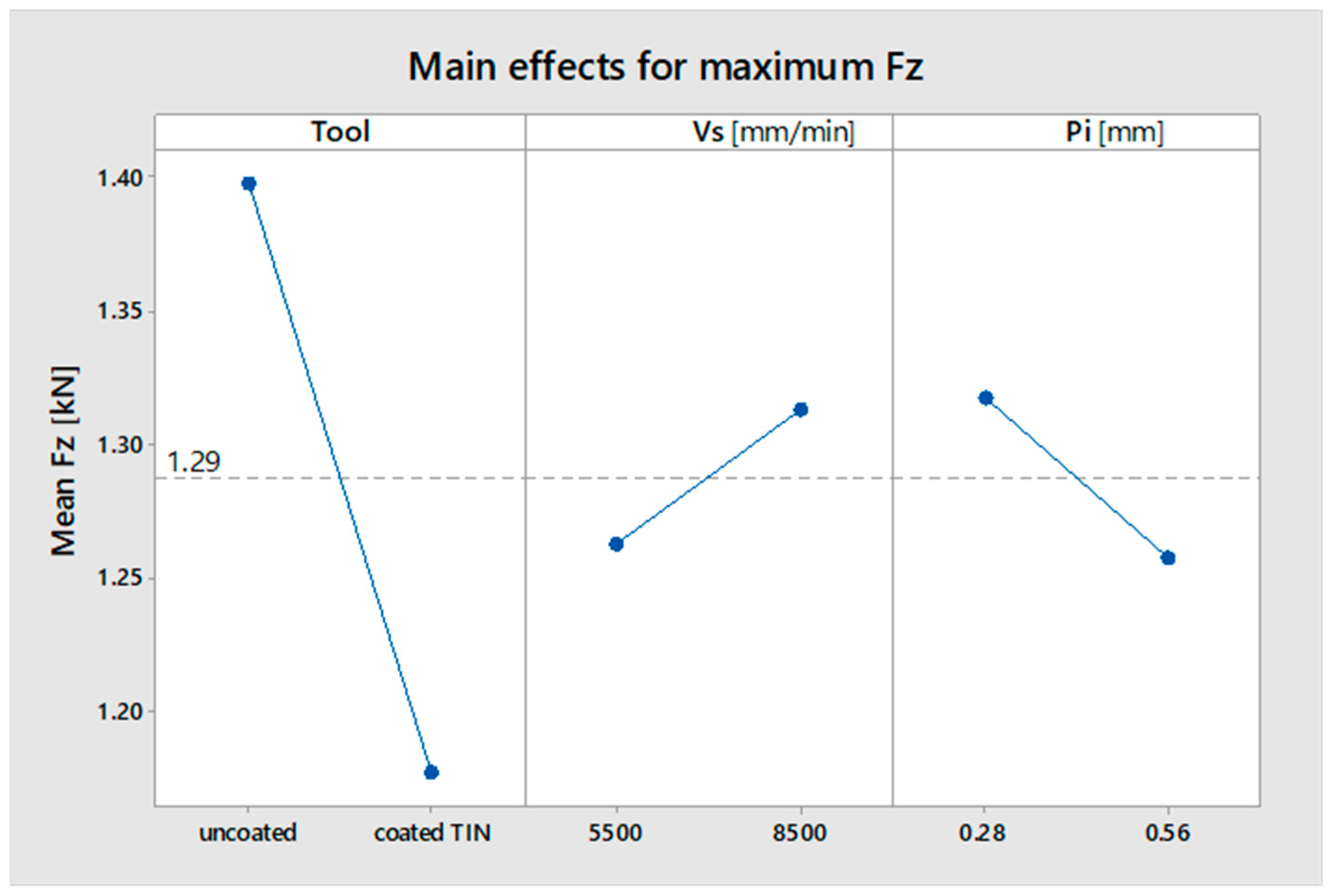
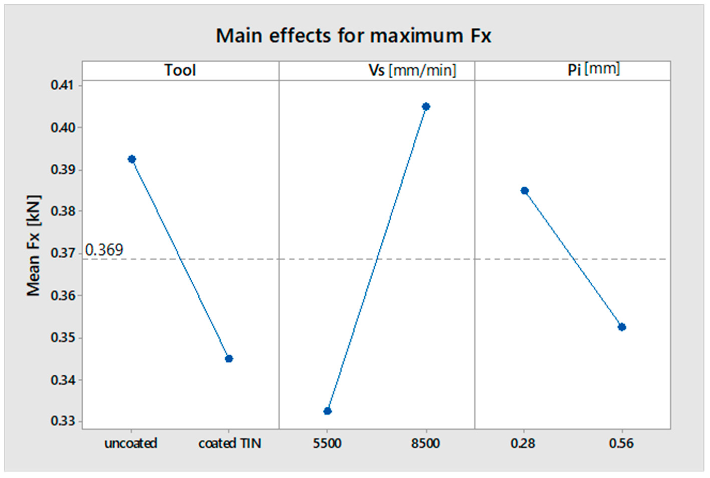
3.2. Influence of Working Parameters on the Components of the Forming Force
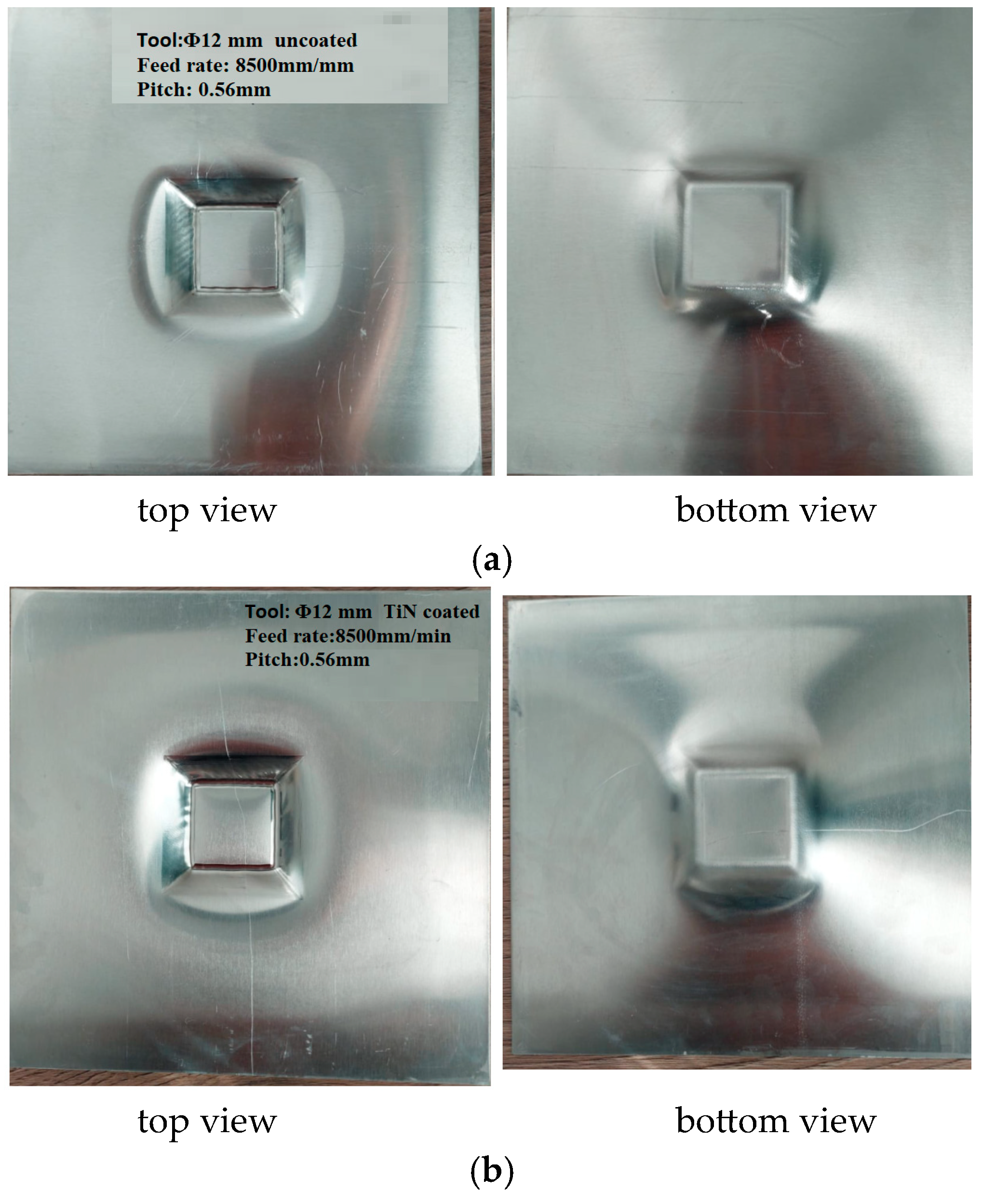
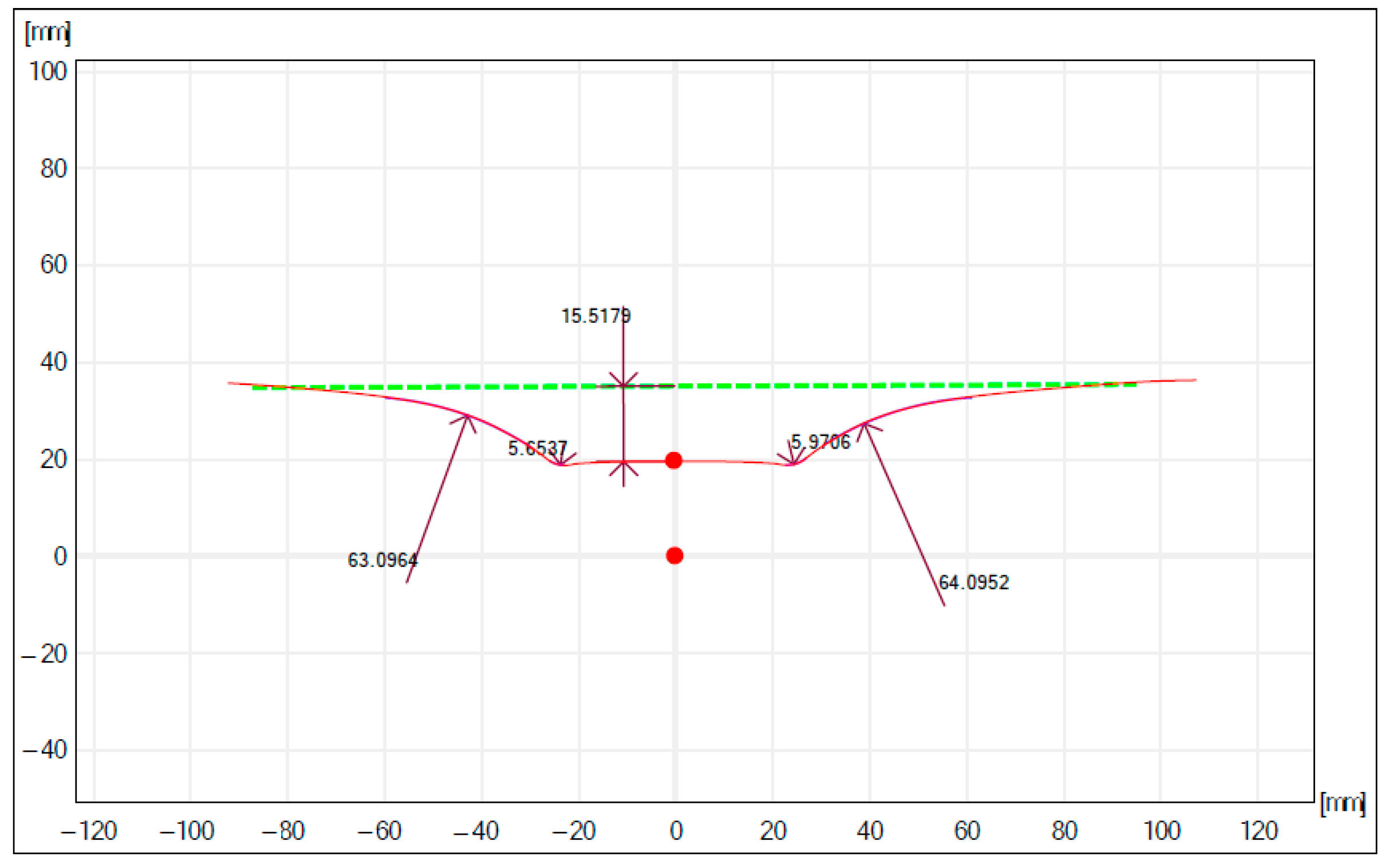
3.3. Execution Accuracy
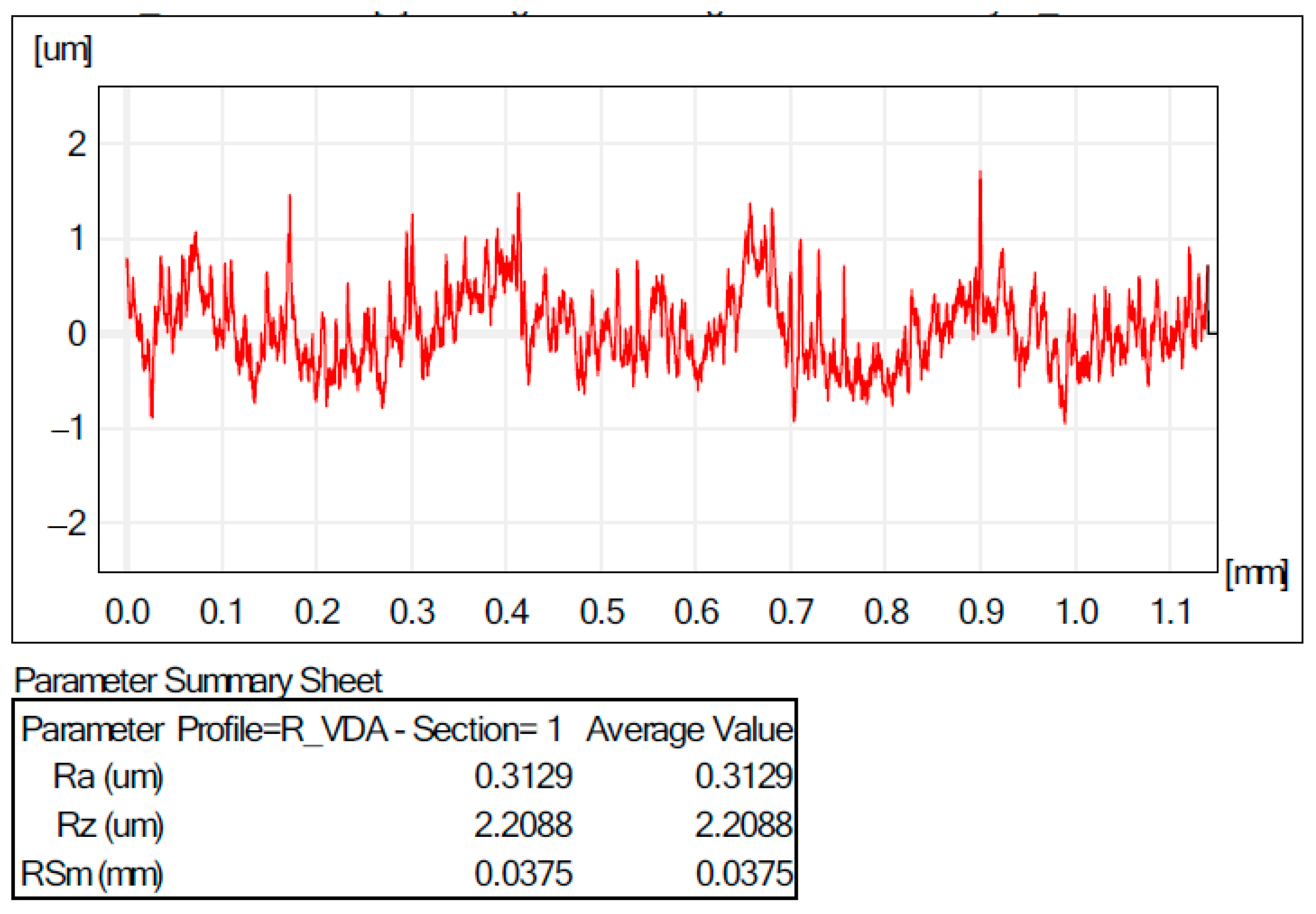
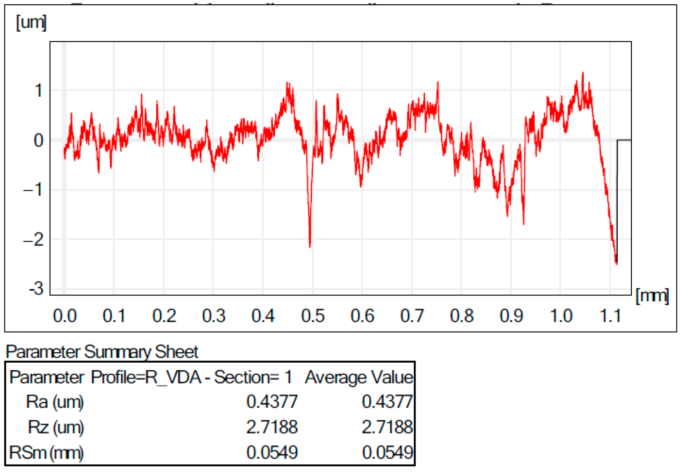
3.4. Quality of the Surfaces Obtained
4. Conclusions
- -
- the temperature is not controlled in the deformed area (with the possibility of improving the material deformability);
- -
- reduced precision of the process (need to use the counter-pouch (tool)/counter-matrice);
- -
- the inclination angle of the wall cannot exceed 70° (under special conditions) because breaks and cracks occur;
- -
- the process is limited and of a lower precision due to the use of a robot for traveling the tool, which has low rigidity. On the other hand, industrial robots can be used in the processing with incremental forming of areas of large assemblies that cannot be placed on the CNC milling machines’ table;
- -
- long processing time compared to classic forming, which recommends it only for small and unique series production.
Author Contributions
Funding
Institutional Review Board Statement
Informed Consent Statement
Data Availability Statement
Conflicts of Interest
References
- Emmens, W.C.; van den Boogaard, A.H. An overview of stabilizing deformation mechanisms in incremental sheet forming. J. Mater. Process. Technol. 2009, 209, 3688–3695. [Google Scholar] [CrossRef]
- Button, S.T. Introduction to Advanced Forming Technologies. In Comprehensive Materials Processing; Hashmi, S., Batalha, G.F., Van Tyne, C.J., Yilbas, B., Eds.; Elsevier: Amsterdam, The Netherlands, 2014; pp. 1–5. [Google Scholar] [CrossRef]
- Zheng, K.; Politis, D.J.; Wang, L.; Lin, J. A review on forming techniques for manufacturing lightweight complex—Shaped aluminium panel components. Int. J. Lightweight Mater. Manuf. 2018, 1, 55–80. [Google Scholar] [CrossRef]
- Kumar, Y.; Kumar, S. Advances in Material Forming and Joining; Springer India: New Delhi, India, 2015; pp. 29–47. [Google Scholar] [CrossRef]
- Duflou, J.R.; Habraken, A.-M.; Cao, J.; Malhotra, R.; Bambach, M.; Adams, D.; Vanhove, H.; Mohammadi, A.; Jeswiet, J. Single point incremental forming: State-of-the-art and prospects. Int. J. Mater. Form. 2018, 11, 743–773. [Google Scholar] [CrossRef]
- Behera, A.K. Ricardo Alves de Sousa, Giuseppe Ingarao, Valentin Oleksik, Single point incremental forming: An assessment of the progress and technology trends from 2005 to 2015. J. Manuf. Process. 2017, 27, 37–62. [Google Scholar] [CrossRef]
- Tisza, M. General overview of sheet incremental forming. Manuf. Eng. 2012, 55, 113–120. [Google Scholar]
- Peng, W.; Ou, H.; Becker, A.; Forming, D.-S.I.; Eng, J.M.S. Double-Sided Incremental Forming: A Review. J. Manuf. Sci. Eng. 2019, 141, 050802. [Google Scholar] [CrossRef]
- Mostafanezhad, H.; Menghari, H.G.; Esmaeili, S.; Shirkharkolaee, E.M. Optimization of two-point incremental forming process of AA1050 through response surface methodology. Measurement 2018, 127, 21–28. [Google Scholar] [CrossRef]
- Li, M.Z.; Cai, Z.Y.; Sui, Z.; Yan, Q.G. Multi-point forming technology for sheet metal. J. Mater. Process. Technol. 2002, 129, 333–338. [Google Scholar] [CrossRef]
- Bhaskar, R.S. Analysis of Various Sheet Incremental Metal Forming Processes: A Review. Int. J. Innov. Sci. Res. Technol. 2017, 2, 128–131. [Google Scholar]
- Ramkumar, K.; Baskar, N.; Elangovan, K.; Narayanan, C.S.; Selvarajan, K.A.; Jesuthanam, C. Comparison of Multi Point Incremental Forming Tool with Single Point Incremental Forming Tool Using FLD, Fractography and 3D-Surface Roughness Analysis on Cr/Mn/Ni/Si Based Stainless Steel. Silicon 2021, 13, 487–494. [Google Scholar] [CrossRef]
- Kumar, Y.; Kumar, S. Experimental and analytical evaluation of Incremental Sheet Hydro-Forming strategies to produce high forming angle sheets. Heliyon 2019, 5, e01801. [Google Scholar] [CrossRef] [PubMed]
- Shamsari, M.; Mirnia, M.J.; Elyasi, M.; Baseri, H. Formability improvement in single point incremental forming of truncated cone using a two-stage hybrid deformation strategy. Int. J. Adv. Manuf. Technol. 2018, 94, 2357–2368. [Google Scholar] [CrossRef]
- Shang, M.; Li, Y.; Yang, M.; Chen, Y.; Bai, L.; Li, P. Wall Thickness Uniformity in ISF of Hydraulic Support: System Design, Finite Element Analysis and Experimental Verification. Machines 2023, 11, 353. [Google Scholar] [CrossRef]
- Bhatt, D.K.; Rana, J.; Shah, K.; Patel, K.J. Incremental Sheet Metal Forming Process: A Review. Int. J. Eng. Res. Technol. 2016, 4, 1–9. [Google Scholar]
- Silva, M.B.; Martins, P.A.F. Two-Point Incremental Forming with Partial Die: Theory and Experimentation. J. Mater. Eng. Perform. 2013, 22, 1018–1027. [Google Scholar] [CrossRef]
- Lu, H.; Kearney, M.; Wang, C.; Liu, S.; Meehan, P.A. Part accuracy improvement in two point incremental forming with a partial die using a model predictive control algorithm. Precis. Eng. 2017, 49, 179–188. [Google Scholar] [CrossRef]
- Young, D.; Jeswiet, J. Wall thickness variations in single-point incremental forming. Proc. Inst. Mech. Eng. Part B J. Eng. Manuf. 2004, 218, 1453–1459. [Google Scholar] [CrossRef]
- Reddy, N.V.; Lingam, R. Double Sided Incremental Forming: Capabilities and Challenges. J. Phys. Conf. Ser. 2018, 1063, 012170. [Google Scholar] [CrossRef]
- Nourmohammadi, A.A.; Elyasi, M.; Mirnia, M.J. Flexibility improvement in two-point incremental forming by implementing multi-point die. Int. J. Adv. Manuf. Technol. 2019, 102, 2933–2952. [Google Scholar] [CrossRef]
- Bhasker, R.S.; Kumar, Y. Process capabilities and future scope of Incremental Sheet Forming (ISF). Mater. Today Proc. 2023, 72, 1014–1019. [Google Scholar] [CrossRef]
- Gatea, S.; Ou, H.; McCartney, G. Review on the influence of process parameters in incremental sheet forming. Int. J. Adv. Manuf. Technol. 2016, 87, 479–499. [Google Scholar] [CrossRef]
- Patel, D.; Gandhi, A. A review article on process parameters affecting Incremental Sheet Forming (ISF). Mater. Today Proc. 2022, 63, 368–375. [Google Scholar] [CrossRef]
- Kim, Y.H.; Park, J.J. Effect of process parameters on formability in incremental forming of sheet metal. J. Mater. Process. Technol. 2002, 130–131, 42–46. [Google Scholar] [CrossRef]
- Maaß, F.; Hahn, M.; Tekkaya, A.E. Interaction of Process Parameters, Forming Mechanisms, and Residual Stresses in Single Point Incremental Forming. Metals 2020, 10, 656. [Google Scholar] [CrossRef]
- Xiao, X.; Kim, C.I.; Lv, X.D.; Hwang, T.S.; Kim, Y.S. Formability and forming force in incremental sheet forming of AA7075-T6 at different temperatures. J. Mech. Sci. Technol. 2019, 33, 3795–3802. [Google Scholar] [CrossRef]
- Shi, X.; Hussain, G.; Zha, G.; Wu, M.; Kong, F. Study on formability of vertical parts formed by multi-stage incremental forming. Int. J. Adv. Manuf. Technol. 2014, 75, 1049–1053. [Google Scholar] [CrossRef]
- Gandla, P.K.; Inturi, V.; Kurra, S.; Radhika, S. Evaluation of surface roughness in incremental forming using image processing based methods. Measurement 2020, 164, 108055. [Google Scholar] [CrossRef]
- Edwards, W.L.; Grimm, T.J.; Ragai, I.; Roth, J.T. Optimum Process Parameters for Springback Reduction of Single Point Incrementally Formed Polycarbonates. Procedia Manuf. 2017, 10, 329–338. [Google Scholar] [CrossRef]
- Ai, S.; Long, H. A review on material fracture mechanism in incremental sheet forming. Int. J. Adv. Manuf. Technol. 2019, 104, 33–61. [Google Scholar] [CrossRef]
- Heggemann, T.; Homberg, W.; Sapli, H. Combined Curing and Forming of Fiber Metal Laminates. Procedia Manuf. 2020, 47, 36–42. [Google Scholar] [CrossRef]
- Ding, Z.; Wang, H.; Luo, J.; Li, N. A review on forming technologies of fibre metal laminates. Int. J. Lightweight Mater. Manuf. 2021, 4, 110–126. [Google Scholar] [CrossRef]
- Magrinho, J.P.G.; Silva, M.B.; Martins, P.A.F. Incremental sheet forming. In Reference Module in Earth Systems and Environmental Sciences; Elsevier: Amsterdam, The Netherlands, 2022. [Google Scholar] [CrossRef]
- Zhang, Q.; Li, G.; Liu, Z.; Zhao, A.; Xiong, X.; Lei, Y. Friction Stir Incremental Forming of AA7075-O Sheets: Experimental Investigations on Performance Evaluation of Formed Parts. Rare Met. Mater. Eng. 2018, 47, 3659–3665. [Google Scholar] [CrossRef]
- Heinz, A.; Haszler, A.; Keidel, C.; Moldenhauer, S.; Benedictus, R.; Miller, W. Recent development in aluminium alloys for aerospace applications. Mater. Sci. Eng. A 2000, 280, 102–107. [Google Scholar] [CrossRef]
- Weblet Importer, (n.d.). Available online: https://european-aluminium.eu/resource-hub/aluminium-automotive-manual/ (accessed on 7 January 2018).
- Harrison, N.R.; Luckey, S.G. Hot stamping of a B-Pillar outer from high strength aluminum sheet AA7075, 2014-01e0981. SAE Int. J. Mater. Manuf. 2014, 7, 567–573. [Google Scholar] [CrossRef]
- Hirsch, J. Recent development in aluminium for automotive applications. Trans. Nonferrous Met. Soc. China 2014, 24, 1995–2002. [Google Scholar] [CrossRef]
- Sousa, R. Incremental Sheet Forming Technologies. In Reference Module in Materials Science and Materials Engineering; Elsevier: Amsterdam, The Netherlands, 2016; ISBN 9780128035818. [Google Scholar] [CrossRef]
- Kridli, G.T.; Friedman, P.A.; Boileau, J.M. Chapter 7—Manufacturing processes for light alloys. Updated by Boileau, J.M.; Mallick, P.K.; Woodhead Publishing in Materials; In Materials, Design and Manufacturing for Lightweight Vehicles, 2nd ed.; Mallick, P.K., Ed.; Woodhead Publishing: Sawston, UK, 2021; pp. 267–320. ISBN 9780128187128. [Google Scholar] [CrossRef]
- Cheng, Z.; Li, Y.; Xu, C.; Liu, Y.; Ghafoor, S.; Li, F. Incremental sheet forming towards biomedical implants: A review. J. Mater. Res. Technol. 2020, 9, 7225–7251. [Google Scholar] [CrossRef]
- Emmens, W.C.; Sebastiani, G.; van den Boogaard, A.H. The technology of Incremental Sheet Forming—A brief review of the history. J. Mater. Process. Technol. 2010, 210, 981–997. [Google Scholar] [CrossRef]
- Jackson, K.; Allwood, J. The mechanics of incremental sheet forming. J. Mater. Process. Technol. 2009, 209, 1158–1174. [Google Scholar] [CrossRef]
- Saotome, Y.; Okamoto, T. An in-situ incremental microforming system for three-dimensional shell structures of foil materials. J. Mater. Process. Technol. 2001, 113, 636–640. [Google Scholar] [CrossRef]
- Obikawa, T.; Satou, S.; Hakutani, T. Dieless incremental micro-forming of miniature shell objects of aluminum foils. Int. J. Mach. Tool Manu. 2009, 49, 906–915. [Google Scholar] [CrossRef]
- Dejardin, S.; Thibaud, S.; Gelin, J.C. Experimental and Numerical Investigations in Single Point Incremental Sheet Forming For Micro parts. AIP Conf. Proc. 2007, 907, 145–150. [Google Scholar]
- Obikawa, T.; Hakutani, T.; Sekine, T.; Numajiri, S.; Matsumura, T.; Yoshino, M. Single-Point Incremental Micro-Forming of Thin Shell Products Utilizing High Formability. J. Adv. Mech. Des. Syst. 2010, 4, 1145–1156. [Google Scholar] [CrossRef]
- Sekine, T.; Obikawa, T. Micro Incremental Forming Characteristics of Stainless Foil. Key Eng. Mater. 2010, 447–448, 346–350. [Google Scholar] [CrossRef]
- Otsu, M.; Hiroshi, T.; Kazuki, T. Micro-incremental forming of Ti and Au foils by indentation method. Key Eng. Mater. 2007, 345–346, 1101–1104. [Google Scholar] [CrossRef]
- Song, X.; Zhang, J.; Zhai, W.; Taureza, M.; Castagne, S.; Danno, A. Numerical and Experimental Study of Micro Single Point Incremental Forming Process. Procedia Eng. 2017, 207, 825–830. [Google Scholar] [CrossRef]
- Vollertsen, F. Categories of size effects. Prod. Eng. 2008, 2, 377. [Google Scholar] [CrossRef]
- Geiger, M.; Vollertsen, F. Fundamentals on the Manufacturing of Sheet Metal Microparts. CIRP Ann. Manuf. Technol. 1996, 45, 277–282. [Google Scholar] [CrossRef]
- Iadicola, M.A.; Foecke, T.; Banovic, S.W. Experimental observations of evolving yield loci in biaxially strained AA5754-O. Int. J. Plast. 2008, 24, 2084–2101. [Google Scholar] [CrossRef]
- Ramesh, R.; Bhattacharya, R.; Williams, G. Effect of ageing on the mechanical behaviour of a novel automotive grade AleMgeSi alloy. Mater. Sci. Eng. A 541 2012, 128–134. [Google Scholar] [CrossRef]
- Abedrabbo, N.; Pourboghrat, F.; Carsley, J. Forming of AA5182-O and AA5754-O at elevated temperatures using coupled thermo-mechanical finite element models. Int. J. Plast. 2007, 23, 841–875. [Google Scholar] [CrossRef]
- Aerospace Aluminum Distributor Supplier. Available online: http://www.aerospace-metals.com/aluminum-distributor.html (accessed on 15 June 2023).
- Wang, A.; Zhong, K.; El Fakir, O.; Liu, J.; Sun, C.; Wang, L.-L.; Lin, J.; Dean, T.A. Springback analysis of AA5754 after hot stamping: Experiments and FE modelling. Int. J. Adv. Manuf. Technol. 2017, 89, 1339–1352. [Google Scholar] [CrossRef]
- Fan, X.; He, Z.; Zheng, K.; Yuan, S. Strengthening Behavior of Al-Cu-Mg Alloy Sheet in Hot Forming-Quenching Integrated Process With Colda^V“Hot Dies. Mater. Des. 2015, 83, 557–565. [Google Scholar] [CrossRef]
- Jawale, K.; Duarte, J.F.; Reis, A.; Silva, B. Microstructural investigation and lubrication study for single point incremental forming of copper, in press. Int. J. Solids Struct. 2018, 21, 145–151, in press. [Google Scholar] [CrossRef]
- Azevedo, N.G.; Farias, J.S.; Bastos, R.P.; Teixeira, P.; Davim, J.P.; De Sousa, R.J.A. Lubrication aspects during single point incremental forming for steel and aluminum materials. Int. J. Precis. Eng. Manuf. 2015, 16, 589–595. [Google Scholar] [CrossRef]
- Mirnia, M.J.; Dariani, B.M.; Vanhove, H.; Duflou, J.R. Thickness improvement in single point incremental forming deduced by sequential limit analysis. Int. J. Adv. Manuf. Tech. 2014, 70, 2029–2041. [Google Scholar] [CrossRef]
- Yang, C.; Wen, T.; Liu, L.; Zhang, S.; Wang, H. Dieless incremental hole-flanging of thin-walled tube for producing branched tubing. J. Mater. Process. Technol. 2014, 214, 2461–2467. [Google Scholar] [CrossRef]
- Bahloul, R. A study on optimal design of process parameters in single point incremental forming of sheet metal by combining Box- Behnken design of experiments, response surface methods and genetic algorithms. Int. J. Adv. Manuf. Technol. 2014, 74, 163–185. [Google Scholar] [CrossRef]
- Li, J.; Bai, T. Numerical simulation and experimental investigation of incremental sheet forming with an elastic support. Int. J. Adv. Manuf. Technol. 2014, 74, 1649–1654. [Google Scholar] [CrossRef]
- Echrif, S.B.M.; Hrairi, M. Materials and Manufacturing Processes Research and Progress in Incremental Sheet Forming Processes. Mater. Manuf. Process. 2011, 26, 1404–1414. [Google Scholar] [CrossRef]
- Araghi, B.T.; Manco, G.L.; Bambach, M.; Hirt, G. Investigation into a new hybrid forming process: Incremental sheet forming combined with stretch forming. CIRP Ann. 2009, 58, 225–228. [Google Scholar] [CrossRef]
- Formisano, A.; Boccarusso, L.; Durante, M. Optimization of Single-Point Incremental Forming of Polymer Sheets through FEM. Materials 2023, 16, 451. [Google Scholar] [CrossRef] [PubMed]
- Rosa-Sainz, A.; Centeno, G.; Silva, M.B.; López-Fernández, J.A.; Martínez-Donaire, A.J.; Vallellano, C. On the Determination of Forming Limits in Polycarbonate Sheets. Materials 2020, 13, 928. [Google Scholar] [CrossRef] [PubMed]
- Jeswiet, J.; Adams, D.; Doolan, M.; McAnulty, T.; Gupta, P. Single point and asymmetric incremental forming. Adv. Manuf. 2015, 3, 253–262. [Google Scholar] [CrossRef]
- Cusanno, A.; Negrini, N.C.; Villa, T.; Farè, S.; Garcia-Romeu, M.L.; Palumbo, G. Post Forming Analysis and In Vitro Biological Characterization of AZ31B Processed by Incremental Forming and Coated With Electrospun Polycaprolactone. ASME. J. Manuf. Sci. Eng. 2021, 143, 011012. [Google Scholar] [CrossRef]
- Singh, S.A.; Priyadarshi, S.; Tandon, P. Comparative Study of Incremental Forming and Elevated Temperature Incremental Forming Through Experimental Investigations on AA 1050 Sheet ASME. J. Manuf. Sci. Eng. 2021, 143, 064501. [Google Scholar] [CrossRef]
- Li, W.; Attallah, M.M.; Essa, K. Experimental and numerical investigations on the process quality and microstructure during induction heating assisted incremental forming of Ti-6Al-4V sheet. J. Mater. Process. Technol. 2022, 299, 117323. [Google Scholar] [CrossRef]
- Kotkunde, N.; Gupta, A.K.; Paresi, P.R.; Singh, S.K. Experimental and Finite Element Studies of Stretch Forming Process for Ti-6Al-4V Alloy at Elevated Temperature. Mater. Today Proc. 2017, 4 Pt D, 5266–5273. [Google Scholar] [CrossRef]
- Cheng, D.-J.; Xu, F.; Xu, S.-H.; Zhang, C.-Y.; Zhang, S.-W.; Kim, S.-J. Minimization of Surface Roughness and Machining Deformation in Milling of Al Alloy Thin-Walled Parts. Int. J. Precis. Eng. Manuf. 2020, 21, 1597–1613. [Google Scholar] [CrossRef]
- Riaz, A.A.; Hussain, G.; Ullah, N.; Wei, H.; Alkahtani, M.; Khan, M.N. An investigation on the effects of tool rotational speed and material temper on post-ISF tensile properties of Al2219 alloy. J. Mater. Res. Technol. 2021, 10, 853–867. [Google Scholar] [CrossRef]
- Kumar, V.; Kumar, R. Investigation of Surface Roughness in Incremental Sheet Forming of AA 2014-T6 using Taguchi’s Method. J. Phys. Conf. Ser. 2020, 1519, 012009. [Google Scholar] [CrossRef]
- Wu, R.; Hu, Q.; Li, M.; Cai, S.; Chen, J. Evaluation of the forming limit of incremental sheet forming based on ductile damage. J. Mater. Process. Technol. 2021, 287, 116497. [Google Scholar] [CrossRef]
- Pandivelan, C.; Jeevanantham, A.K.; Sathiyanarayanan, C. Optimization Study on Incremental Forming of Sheet Metal AA5052 for Variable Wall Angle using CNC Milling Machine. Mater. Today Proc. 2018, 5 Pt 2, 12832–12836. [Google Scholar] [CrossRef]
- Kumar Singh, A.; Agrawal, A. Formability Analysis of AA1200 H14 Aluminum Alloy Using Single Point Incremental Forming Process. Trans. Indian Inst. Met. 2020, 73, 1975–1984. [Google Scholar] [CrossRef]
- Rashid, H.; Hussain, G.; Rehman, K.; Khan, S.; Alkahtani, M.; Abidi, M.H. Characterization of residual stresses in an asymmetrical shape produced through incremental forming. CIRP J. Manuf. Sci. Technol. 2020, 31, 478–491. [Google Scholar] [CrossRef]
- Shojaeefrd, M.; Khalkhali, A.; Shahbaz, S. Sensitivity analysis and optimization of the surface roughness in the incremental forming of mild steel sheets. Sci. Iran. 2021, 28, 316–325. [Google Scholar] [CrossRef]
- Dabwan, A.; Ragab, A.E.; Saleh, M.A.; Anwar, S.; Ghaleb, A.M.; Rehman, A.U. Study of the Effect of Process Parameters on Surface Profile Accuracy in Single-Point Incremental Sheet Forming of AA1050-H14 Aluminum Alloy. Adv. Mater. Sci. Eng. 2020, 2020, 7265941. [Google Scholar] [CrossRef]
- Mandaloi, G.; Nagargoje, A.; Gupta, A.K.; Banerjee, G.; Shahare, H.Y.; Tandon, P. A Comprehensive Review on Experimental Conditions, Strategies, Performance, and Applications of Incremental Forming for Deformation Machining, ASME. J. Manuf. Sci. Eng. 2022, 144, 110802. [Google Scholar] [CrossRef]
- Shrivastava, P.; Tandon, P. Microstructure and texture based analysis of forming behavior and deformation mechanism of AA1050 sheet during Single Point Incremental Forming. J. Mater. Process. Technol. 2019, 266, 292–310. [Google Scholar] [CrossRef]
- Chang, Z.; Chen, J. A new void coalescence mechanism during incremental sheet forming: Ductile fracture modeling and experimental validation. J. Mater. Process. Technol. 2021, 298, 117319. [Google Scholar] [CrossRef]
- Nirala, H.K.; Agrawal, A. Reprint of: Residual stress inclusion in the incrementally formed geometry using Fractal Geometry Based Incremental Toolpath (FGBIT). J. Mater. Process. Technol. 2021, 287, 116623. [Google Scholar] [CrossRef]
- Kubit, A.; Al-Sabur, R.; Gradzik, A.; Ochał, K.; Slota, J.; Korzeniowski, M. Investigating Residual Stresses in Metal-Plastic Composites Stiffening Ribs Formed Using the Single Point Incremental Forming Method. Materials 2022, 15, 8252. [Google Scholar] [CrossRef] [PubMed]
- Najm, S.M.; Paniti, I.; Trzepieciński, T.; Nama, S.A.; Viharos, Z.J.; Jacso, A. Parametric Effects of Single Point Incremental Forming on Hardness of AA1100 Aluminium Alloy Sheets. Materials 2021, 14, 7263. [Google Scholar] [CrossRef] [PubMed]
- Li, R.; Wang, T. Research on Single Point Incremental Forming Characteristics of Perforated TA1 Sheet. Metals 2022, 12, 1944. [Google Scholar] [CrossRef]
- Oleksik, V.; Trzepieciński, T.; Szpunar, M.; Chodoła, Ł.; Ficek, D.; Szczęsny, I. Single-Point Incremental Forming of Titanium and Titanium Alloy Sheets. Materials 2021, 14, 6372. [Google Scholar] [CrossRef] [PubMed]
- Bai, L.; Li, Y.; Yang, M.; Lin, Y.; Yuan, Q.; Zhao, R. Modeling and Analysis of Single Point Incremental Forming Force with Static Pressure Support and Ultrasonic Vibration. Materials 2019, 12, 1899. [Google Scholar] [CrossRef]
- Trzepieciński, T.; Kubit, A.; Dzierwa, A.; Krasowski, B.; Jurczak, W. Surface Finish Analysis in Single Point Incremental Sheet Forming of Rib-Stiffened 2024-T3 and 7075-T6 Alclad Aluminium Alloy Panels. Materials 2021, 14, 1640. [Google Scholar] [CrossRef]
- Available online: https://www.atlassteels.com.au/documents/Atlas_Aluminium_datasheet_3003_rev_Oct_2013.pdf (accessed on 26 May 2023).
- Available online: https://www.theworldmaterial.com/din-en-1-2379-steel-x153crmov12-material/ (accessed on 26 May 2023).
- Available online: https://www.robots.com/robots/kuka-kr-210 (accessed on 26 May 2023).
- Available online: https://www.kuka.com/-/media/kuka-downloads/imported/8350ff3ca11642998dbdc81dcc2ed44c/pf0031_kr_2102_k_en.pdf (accessed on 3 May 2023).
- 2823-12. Available online: https://www.sensor-hbm.com (accessed on 4 May 2023).
- QuantumX MX840B/MX440B: Universal Data Acquisition Module. Available online: https://www.hbm.com/en/2129/quantumx-mx840b-8-channel-universalamplifier/ (accessed on 23 September 2022).
- Available online: https://www.archimina.ro/articole/Articles-Detail/52-Placarea-sculelor-aschietoare-cu-Nitrura-de-Titan---TiN/0 (accessed on 6 March 2021).
- Available online: http://magnum.engineering.upm.ro/~gabriela.strnad/Tehnologia%20materialelor%20I%20-%20curs%20licenta%20an%20I/2%20LABORATOR/saptamana%205-6/Incercarea%20de%20ambutisare%20prin%20metoda%20Erichsen.pdf (accessed on 11 March 2021).
- Oraon, M.; Sharma, V. Predicting Force in Single Point Incremental Forming by Using Artificial Neural Network. Int. J. Eng. 2018, 31, 88–95. [Google Scholar]
- Harfoush, A.; Haapala, K.R.; Tabei, A. Application of Artificial Intelligence in Incremental Sheet Metal Forming: A Review. Procedia Manuf. 2021, 53, 606–617. [Google Scholar] [CrossRef]
- Arshad, S. Single Point Incremental Forming. A Study of Forming Parameters, Forming Limits and Part Accuracy of Aluminium 2024, 6061 and 7475 Alloys. Ph.D. Thesis, KTH Royal Institute of Technology, Stockholm, Sweden, June 2012. [Google Scholar]
- Trzepiecinski, T.; Oleksik, V.; Pepelnjak, T.; Najm, S.M.; Paniti, I.; Maji, K. Emerging Trends in Single Point Incremental Sheet Forming of Lightweight Metals. Metals 2021, 11, 1188. [Google Scholar] [CrossRef]


| No. crt. | Material | Analysis | References |
|---|---|---|---|
| 1 | polymer sheets | optimization of forming forces | [68] |
| 2 | polycarbonate | formability limits (necking, fracture) | [69] |
| 3 | titanium and magnesium | surface roughness, design and production of parts, maximum forming angle | [70] |
| 4 | AZ31B-H24 (magnesium sheet) | temperature effect on roughness, microstructure and hardness, coating of parts using electrospun polycaprolactone | [71] |
| 5 | AA 1050 (aluminium alloy sheet) | role of heat in formability, comparation between elevated temperature incremental forming and conventional method | [72] |
| 6 | Ti-6Al-4V (titanium sheet) | analysis of forming force, surface roughness, geometric accuracy, thickness profile, micro-hardness for induction heating SPIF; finite element analysis—FEA (strain and stresses), Arrhenius model | [73] |
| 7 | Ti-6Al-4V (titanium sheet) | tensile test, stretch forming experiments (at 400 °C), FEA | [74] |
| 8 | Al alloy 5083 (aluminium alloy sheet) | surface roughness, deformation of thin-walled, mathematical models, optimization | [75] |
| 9 | Al2219-O, AA2219-T6 (aluminium alloy sheet) | tool rotational speed influence on tensile strength, microstructure analysis | [76] |
| 10 | AA 2014-T6 (aluminium alloy sheet) | surface roughness, Taguchi’s analysis, input parameters influence | [77] |
| 11 | AA1050-H111 (aluminium alloy sheet) | fracture forming limit, failure mechanism, ductile fracture, tensile stress, process parameter influence | [78] |
| 12 | AA 5052 (aluminium alloy sheet) | formability, optimization, variable wall angle, orthogonal array | [79] |
| 13 | AA1200 H14 (aluminium alloy sheet) | formability analysis, ANOVA analysis, microstructure | [80] |
| 14 | AA 1050 (aluminium alloy sheet) | residual stresses, hole drill test, Taguchi analysis | [81] |
| 15 | St12 (mild steel sheet) | surface roughness, Taguchi analysis, ANOVA methodology | [82] |
| 16 | AA1050-H14 (aluminium alloy sheet) | surface profile, influence of process parameters | [83] |
| 17 | Monolithic geometry | performance, strategies of experimental conditions, applications | [84] |
| 18 | AA1050 (aluminium alloy sheet) | microstructure, texture based analysis, structural and morphological analysis | [85] |
| 19 | AA2024, AA6061 (aluminium alloy sheet) | void coalescence and cluster, ductile fracture, GTN model, FEA | [86] |
| 20 | Al 6063-T6 (aluminium alloy sheet) | residual stress, nanoindentation fractal geometry | [87] |
| 21 | LITECOR® composite material (metal-plastic) | residual stresses, structural and morphological analysis | [88] |
| 22 | AA1100 (aluminium alloy sheet) | hardness, artificial neural network, relative importance | [89] |
| 23 | TA1 (titanium sheet) | FEM, tensile test, thinning ratio, forming strain | [90] |
| 24 | titanium and titanium alloy sheets | microstructure, friction, lubrication | [91] |
| 25 | AL1060 (aluminium alloy sheet) | ultrasonic vibration, forming force, experimental verification, analytical modelling | [92] |
| 26 | 2024-T3, 7075-T6 (aluminium alloy panels) | surface finish, surface roughness, surface topography, artificial neural networks modelling | [93] |
| No. | Tool | Feed Rate, Vs [mm/min] | Forming Step, Pi [mm] | Fz [kN] | Fx [kN] | Fy [kN] |
|---|---|---|---|---|---|---|
| 1. | uncoated | 5500 | 0.28 | 1.2 | 0.4 | 0.35 |
| 2. | uncoated | 5500 | 0.56 | 1.39 | 0.38 | 0.4 |
| 3. | uncoated | 8500 | 0.28 | 1.0 | 0.21 | 0.17 |
| 4. | uncoated | 8500 | 0.56 | 1.41 | 0.4 | 0.47 |
| 5. | coated with TIN | 5500 | 0.28 | 1.25 | 0.37 | 0.35 |
| 6. | coated with TIN | 5500 | 0.56 | 1.38 | 0.42 | 0.44 |
| 7. | coated with TIN | 8500 | 0.28 | 1.26 | 0.4 | 0.41 |
| 8. | coated with TIN | 8500 | 0.56 | 1.41 | 0.37 | 0.41 |
| Case | Feed Rate | Forming Step | Maximum Force Fz | Maximum Force Fx | Maximum Force Fy |
|---|---|---|---|---|---|
| [mm/min] | [mm] | [N] | [N] | [N] | |
| Experimental | 5500 | 0.56 | 1390 | 380 | 400 |
| Simulation | 5500 | 0.56 | 1395 | 410 | 420 |
| Diference [%] | 0.36 | 7.89 | 5 | ||
| Case | Feed Rate | Forming Step | Maximum Force Fz | Maximum Force Fx | Maximum Force, Fy |
|---|---|---|---|---|---|
| [mm/min] | [mm] | [N] | [N] | [N] | |
| Experimental | 5500 | 0.56 | 1380 | 420 | 440 |
| Simulation | 5500 | 0.56 | 1490 | 440 | 450 |
| Diference [%] | 7.97 | 4.76 | 2.27 | ||
| Factor | No. Degrees of Freedom (DF) | Adj. MS | F Value | Threshold of Significance, p | Statistical Significance * |
|---|---|---|---|---|---|
| Tool | 1 | 0.0968 | 11.90 | 0.026 | S |
| Feed rate, Vs | 1 | 0.005 | 0.61 | 0.477 | NS |
| Forming step, Pi | 1 | 0.0072 | 0.88 | 0.400 | NS |
| Factor | No. Degrees of Freedom (DF) | Adj. MS | F Value | Threshold of Significance, p | Statistical Significance * |
|---|---|---|---|---|---|
| Tool | 1 | 0.004513 | 1.31 | 0.316 | NS |
| Feed rate, Vs | 1 | 0.010513 | 3.06 | 0.155 | NS |
| Forming step, Pi | 1 | 0.002113 | 0.61 | 0.477 | NS |
Disclaimer/Publisher’s Note: The statements, opinions and data contained in all publications are solely those of the individual author(s) and contributor(s) and not of MDPI and/or the editor(s). MDPI and/or the editor(s) disclaim responsibility for any injury to people or property resulting from any ideas, methods, instructions or products referred to in the content. |
© 2023 by the authors. Licensee MDPI, Basel, Switzerland. This article is an open access article distributed under the terms and conditions of the Creative Commons Attribution (CC BY) license (https://creativecommons.org/licenses/by/4.0/).
Share and Cite
Coman, C.C.; Mazurchevici, S.-N.; Carausu, C.; Nedelcu, D. Analysis of Incremental Sheet Forming of Aluminum Alloy. Materials 2023, 16, 6371. https://doi.org/10.3390/ma16196371
Coman CC, Mazurchevici S-N, Carausu C, Nedelcu D. Analysis of Incremental Sheet Forming of Aluminum Alloy. Materials. 2023; 16(19):6371. https://doi.org/10.3390/ma16196371
Chicago/Turabian StyleComan, Costel Catalin, Simona-Nicoleta Mazurchevici, Constantin Carausu, and Dumitru Nedelcu. 2023. "Analysis of Incremental Sheet Forming of Aluminum Alloy" Materials 16, no. 19: 6371. https://doi.org/10.3390/ma16196371
APA StyleComan, C. C., Mazurchevici, S.-N., Carausu, C., & Nedelcu, D. (2023). Analysis of Incremental Sheet Forming of Aluminum Alloy. Materials, 16(19), 6371. https://doi.org/10.3390/ma16196371