
Chemical Corrosion-Water-Confining Pressure Coupling Damage Constitutive Model of Rock Based on the SMP Strength Criterion

Abstract
:1. Introduction
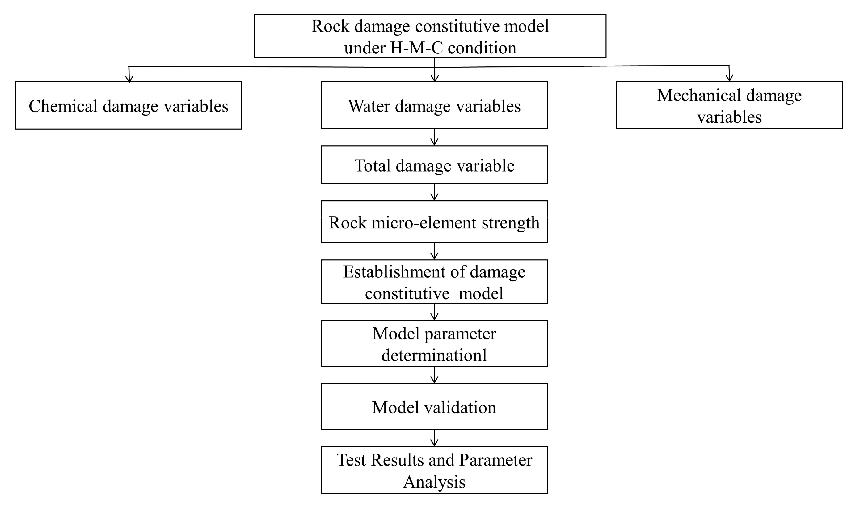
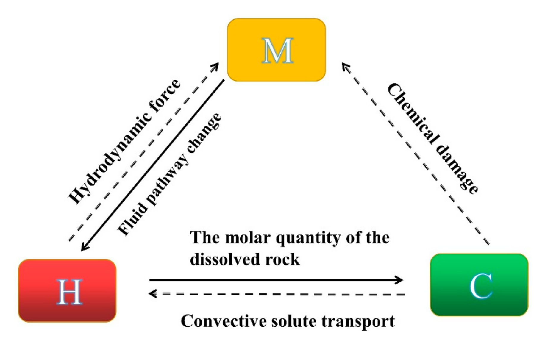
2. Establishment of Rock Damage Constitutive Model under H-M-C Condition
2.1. Methodology
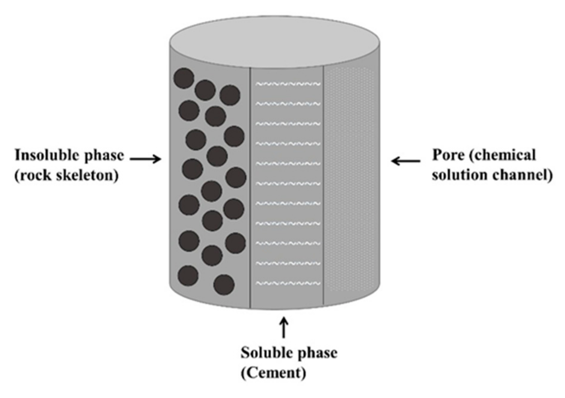
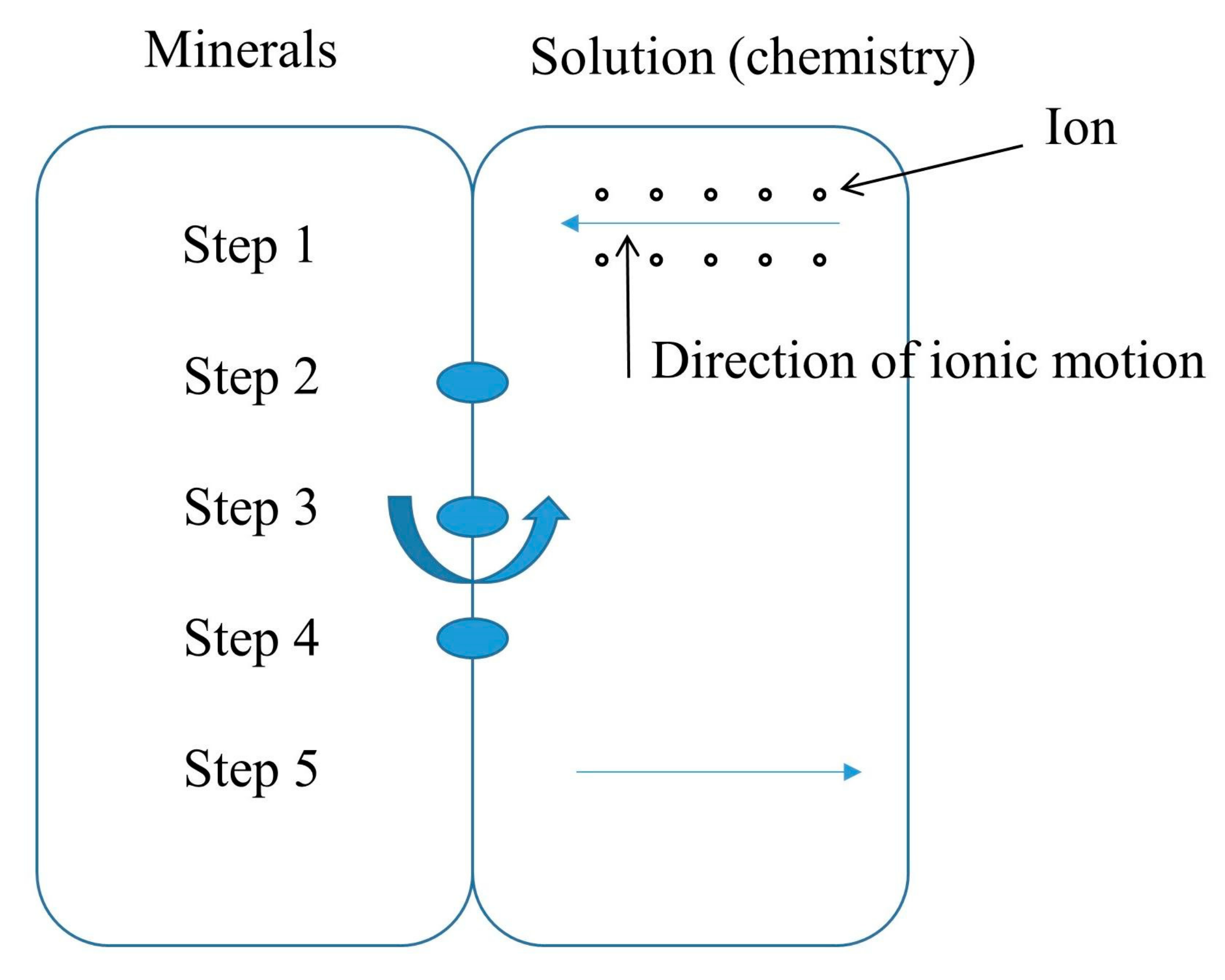
2.2. Determination of Chemical Damage Variables
2.3. Determination of Water Damage Variables
2.4. Determination of Mechanical Damage Variables
2.5. Determination of Total Damage Variable of Rock under H-M-C Condition
2.6. Determination of Rock Micro-Element Strength under Confining Pressure
2.7. Rock Damage Constitutive Model under H-M-C Condition
3. Model Parameter Determination
4. The Validation of Rock Damage Constitutive Model under H-M-C Condition
Parameter Identification
- (1)
- Sandstone reacts with acid in the following main ways:
- (2)
- Sandstone reacts with water in the following main way:
5. Test Results and Parameter Analysis
6. Conclusions
- (1)
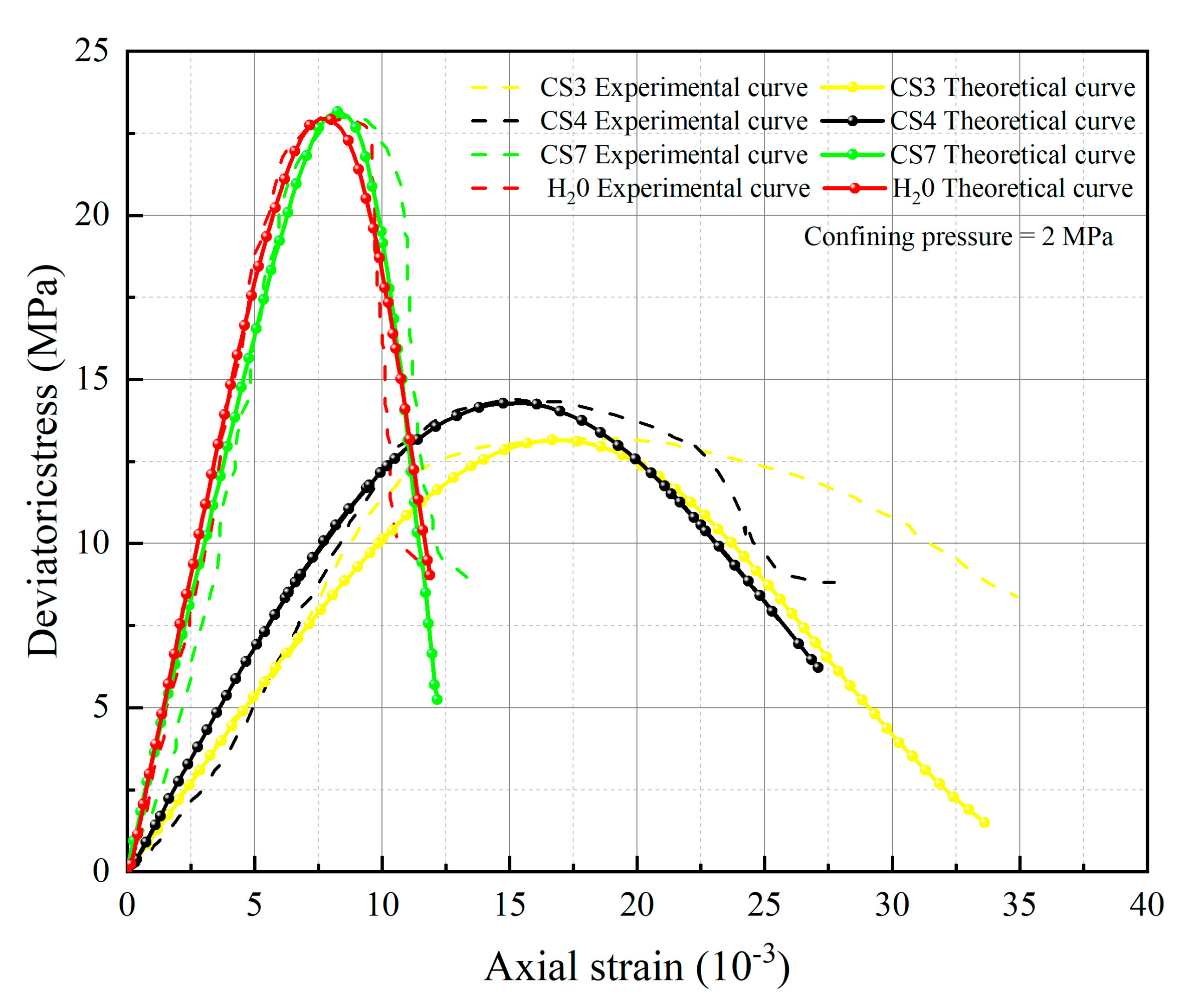
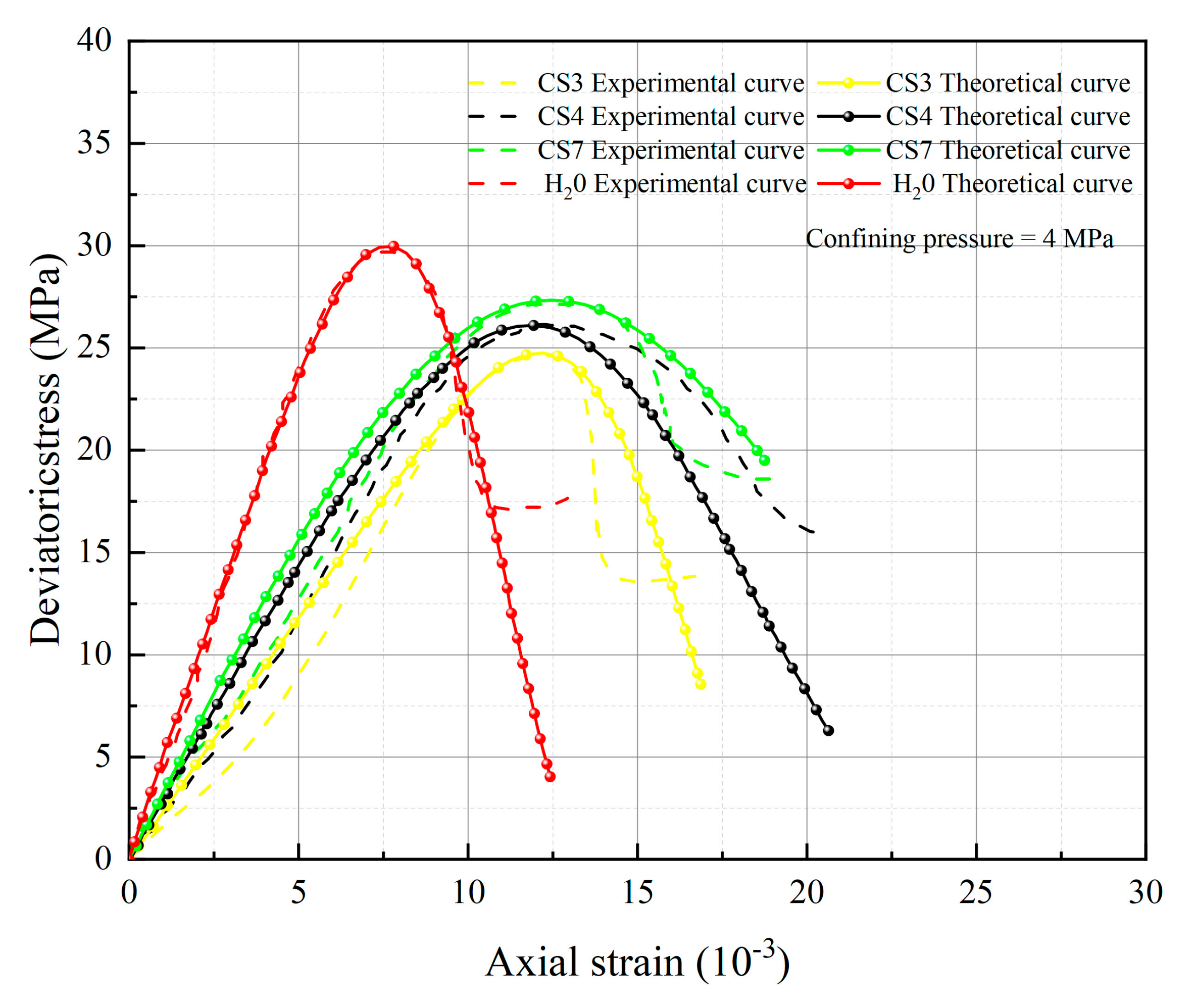
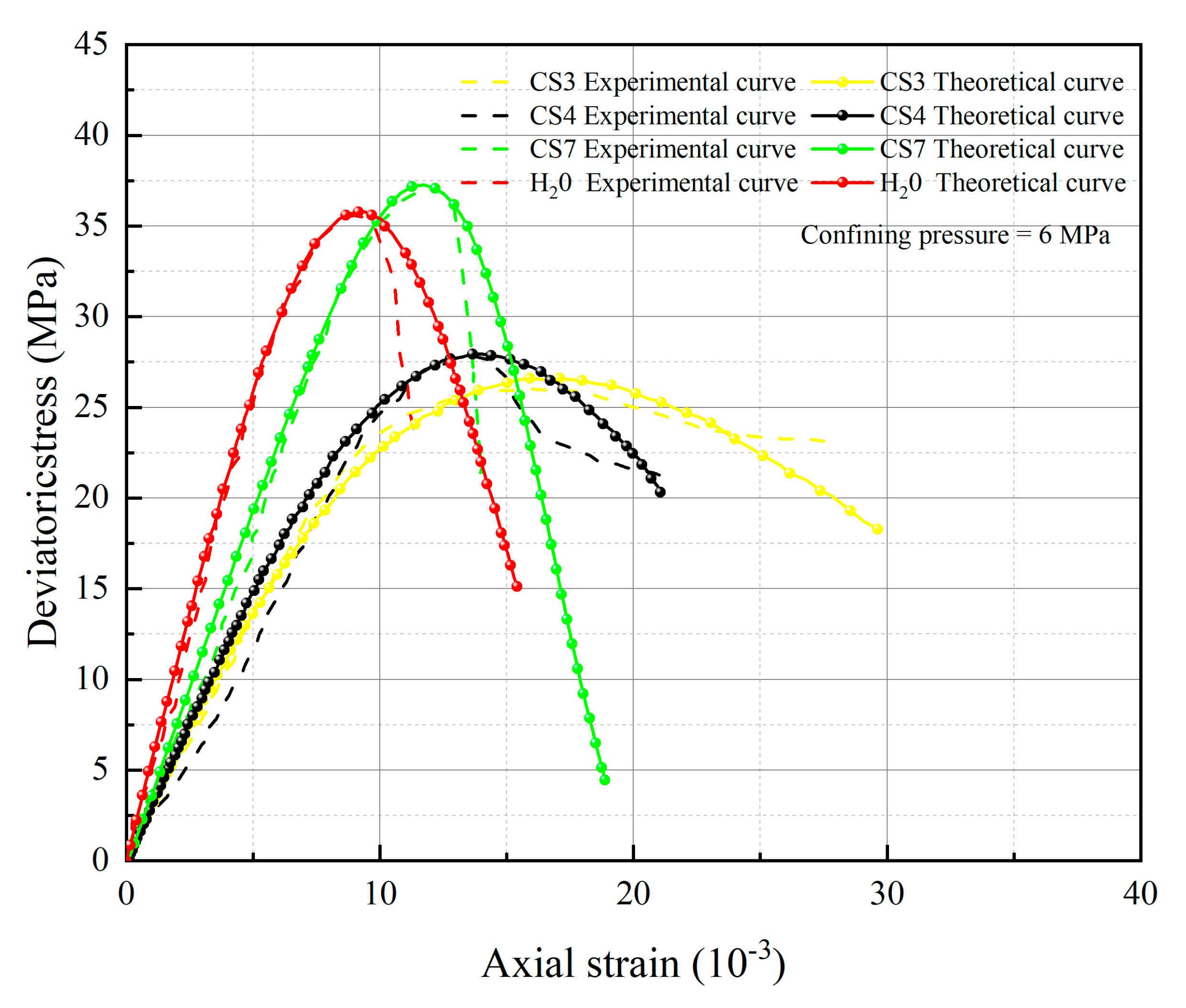
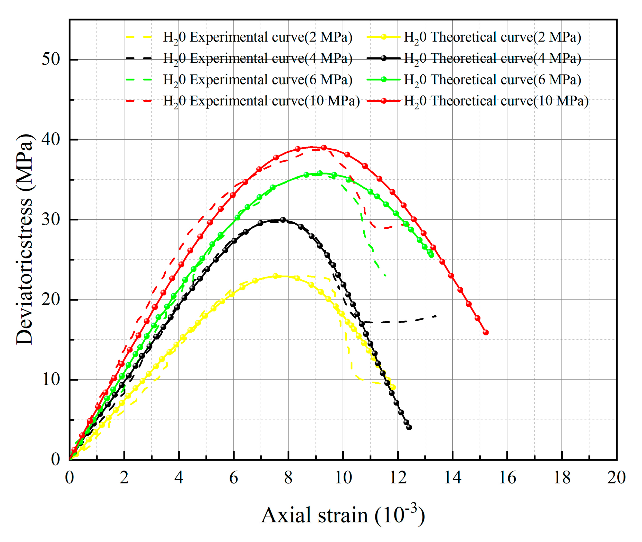
- The spatial mobilized plane (SMP) criterion considering axial stress is introduced, the total damage variable DS considering chemical damage, water damage and mechanical damage is deduced, and the rock damage constitutive model considering chemical-mechanics-hydro (C-M-H) coupled damage is established, which can reflect the stress–strain characteristics in the process of rock triaxial compression: With the increase of confining pressure, the peak stress and strain of rock under the same conditions increase; chemical damage and water damage will lead to the decrease of rock strength, and the degree of decrease will increase with the decrease of pH value.
- (2)
- Stone is selected as the sample for acid corrosion treatment at pH 3, 4, and 7, and a chemical damage factor is defined that coupled the pH value and duration of exposure. The proposed damage constitutive model employs the extremum method to ascertain the two Weibull distribution parameters (m and F0) by theoretical derivation and exhibits satisfactory conformity between the theoretical and experimental curves. The damage constitutive model can be consistent in the stress–strain characteristics of the rock triaxial compression process, which verifies the rationality and reliability of the model parameters.
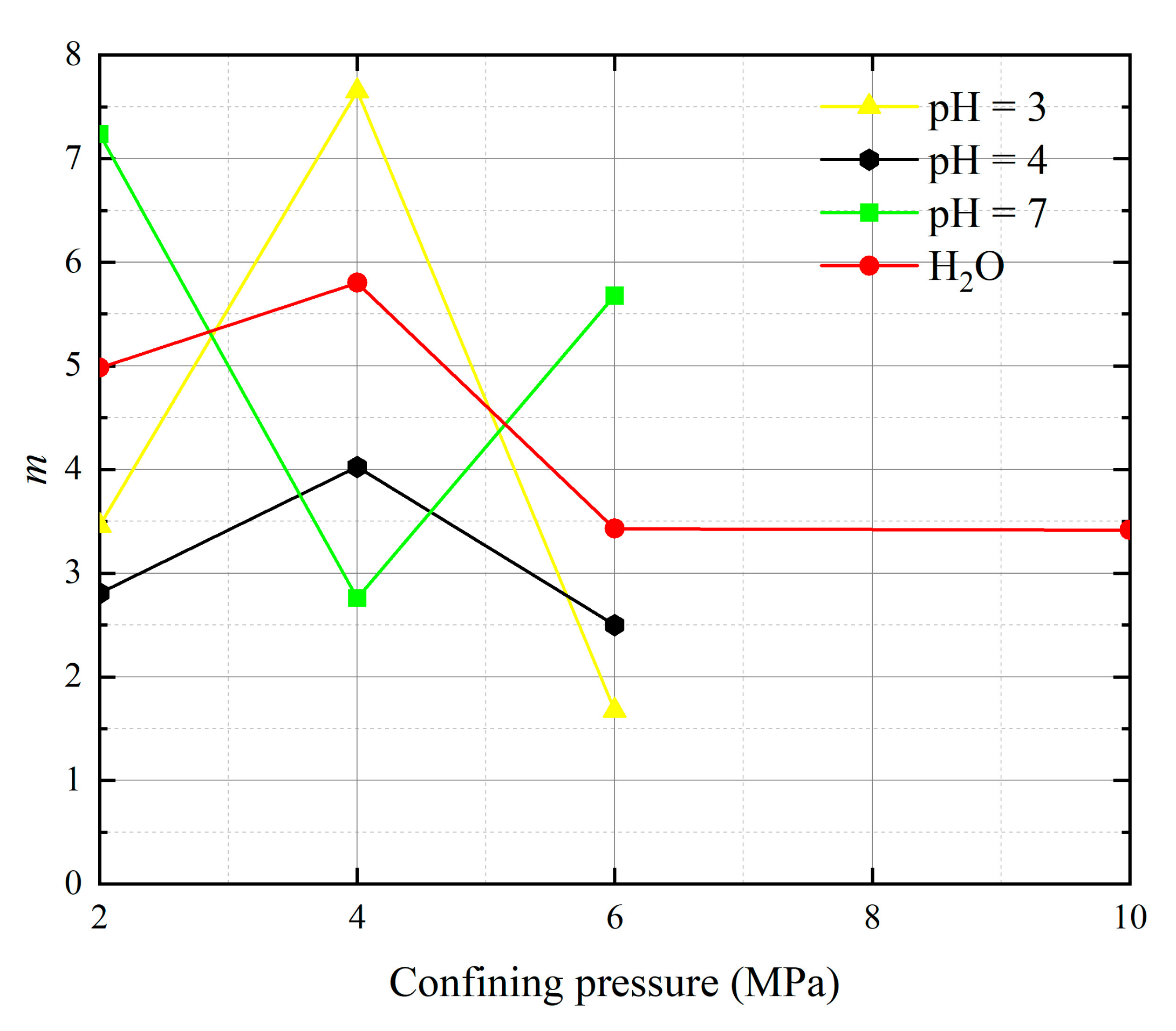
- (3)
- The parameters m and F0 under the SMP criterion are still closely linked to the strength of rock microelements and the macroscopic average strength of rock. The analysis of 13 groups of comparative data shows the stress peak of the curve increases with the increase of damage model parameters F0 and m. At constant confining pressure, the parameter m shows an overall increasing trend with decreasing pH value. The larger the value of m, the greater the degree of corrosion difference of the rock body in the region. When m is unchanged, as F0 increases, rock peak strength increases.
- (4)
- In terms of the validation of the rock damage constitutive model considering chemical-mechanics-hydro (C-M-H) coupled damage, this study adopts the experimental data from the current literature to validate the chemical damage, water damage, and force damage separately, the verification method is not a true coupling. In the future, we will conduct some experiments on rocks under the coupling of water chemistry and confining pressure to further validate this damage constitutive model.
- (5)
- When considering the heterogeneity of the rock itself, the damage constitutive model established in this paper has no specific rock type parameters, and the required model parameters (m and F0) can be obtained through routine triaxial tests in the laboratory. The modified damage constitutive model can not only be applied to the chemical-mechanics-hydro (C-M-H) coupled damaged sandstone, but also can well describe the degree of damage and strength characteristics in the pre-peak stage under triaxial compression. It has certain theoretical significance for mining and railway construction that traverses the areas affected by acid rain and an intense rainfall climate.
Author Contributions
Funding
Informed Consent Statement
Data Availability Statement
Conflicts of Interest
References
- Cui, P.; Ge, Y.; Li, S.; Li, Z.; Xu, X.; Zhou, G.G.; Chen, H.; Wang, H.; Lei, Y.; Zhou, L. Scientific challenges in disaster risk reduction for the Sichuan–Tibet Railway. Eng. Geol. 2022, 309, 106837. [Google Scholar] [CrossRef]
- Sha, A.; Ma, B.; Wang, H.; Hu, L.; Mao, X.; Zhi, X.; Chen, H.; Liu, Y.; Ma, F.; Liu, Z. Highway constructions on the Qinghai–Tibet Plateau: Challenge, research and practice. J. Road Eng. 2022, 2, 1–60. [Google Scholar] [CrossRef]
- Pathiranagei, S.V.; Gratchev, I. Coupled thermo-mechanical constitutive damage model for sandstone. J. Rock Mech. Geotech. 2022, 14, 1710–1721. [Google Scholar] [CrossRef]
- Basu, A.; Ram, B.K.; Nanda, N.K.; Nayak, S.S. Deterioration of shear strength parameters of limestone joints under simulated acid rain condition. Int. J. Rock Mech. Min. 2020, 135, 104508. [Google Scholar] [CrossRef]
- Du, X.; Chen, Y.; Fernández-Steeger, T.M. Advancement of Functionalized Mineral Materials and Rock. Materials 2023, 16, 3375. [Google Scholar] [CrossRef] [PubMed]
- Brünig, M.; Koirala, S.; Gerke, S. A stress-state-dependent damage criterion for metals with plastic anisotropy. Int. J. Damage Mech. 2023, 32, 811–832. [Google Scholar] [CrossRef]
- Rim, H.; Chen, Y.; Tokgo, J.; Du, X.; Li, Y.; Wang, S. Time-Dependent Effect of Seepage Force on Initiation of Hydraulic Fracture around a Vertical Wellbore. Materials 2023, 16, 2012. [Google Scholar] [CrossRef]
- Frenelus, W.; Peng, H.; Zhang, J. Creep behavior of rocks and its application to the long-term stability of deep rock tunnels. Appl. Sci. 2022, 12, 8451. [Google Scholar] [CrossRef]
- Görthofer, J.; Schneider, M.; Hrymak, A.; Böhlke, T. A convex anisotropic damage model based on the compliance tensor. Int. J. Damage Mech. 2022, 31, 43–86. [Google Scholar] [CrossRef]
- Khan, N.M.; Cao, K.; Emad, M.Z.; Hussain, S.; Rehman, H.; Shah, K.S.; Muhammad, A. Development of Predictive Models for Determination of the Extent of Damage in Granite Caused by Thermal Treatment and Cooling Conditions Using Artificial Intelligence. Mathematics 2022, 10, 2883. [Google Scholar] [CrossRef]
- Feng, W.; Rao, P.; Nimbalkar, S.; Chen, Q.; Cui, J.; Ouyang, P. The Utilization of a Coupled Electro-Thermal-Mechanical Model of High-Voltage Electric Pulse on Rock Fracture. Materials 2023, 16, 1693. [Google Scholar] [CrossRef] [PubMed]
- Rodriguez Padilla, A.M.; Oskin, M.E.; Milliner, C.W.; Plesch, A. Accrual of widespread rock damage from the 2019 Ridgecrest earthquakes. Nat. Geosci. 2022, 15, 222–226. [Google Scholar] [CrossRef]
- Gutiérrez-Ch, J.G.; Senent, S.; Zeng, P.; Jimenez, R. DEM simulation of rock creep in tunnels using Rate Process Theory. Comput. Geotech. 2022, 142, 104559. [Google Scholar] [CrossRef]
- Liu, G.; Chen, Y.; Rim, H.; Azzam, R. Viscoplastic solutions of time-dependent deformation for tunnels in swelling rock mass considering stress release. J. Rock Mech. Geotech. 2023, 15, 2053–2071. [Google Scholar] [CrossRef]
- Chen, Q.; Chen, Y.; Xiao, P.; Du, X.; Pan, Y.; Azzam, R. Mechanical properties and damage constitutive model of sandstone after acid corrosion and high temperature treatments. Int. J. Min. Sci. Technol. 2023, 33, 747–760. [Google Scholar] [CrossRef]
- Zhang, R.; Shi, Z.; Yardley, V.A.; Lin, J. A CDM-based unified viscoplastic constitutive model of FLCs and FFLCs for boron steel under hot stamping conditions. Int. J. Damage Mech. 2022, 31, 1373–1395. [Google Scholar] [CrossRef]
- Ding, W.; Wang, H.; Chen, H.; Ma, T. Mechanical Damage and Chemical Dissolution Kinetic Features of Limestone under Coupled Mechanical-Hydrological-Chemical Effects. Geofluids 2021, 2021, 1810768. [Google Scholar] [CrossRef]
- López, D.; Chamat, N.M.; Galeano-Caro, D.; Páramo, L.; Ramirez, D.; Jaramillo, D.; Franco, C.A. Use of nanoparticles in completion fluids as dual effect treatments for well stimulation and clay swelling damage inhibition: An assessment of the effect of nanoparticle chemical nature. Nanomaterials 2023, 13, 388. [Google Scholar] [CrossRef]
- Huang, X.; Pang, J.; Liu, G.; Chen, Y. Experimental study on physicomechanical properties of deep sandstone by coupling of dry-wet cycles and acidic environment. Adv. Civ. Eng. 2020, 2020, 2760952. [Google Scholar] [CrossRef]
- Liu, X.; Wang, S.; Wang, E.; Xue, Q. Double-medium constitutive model of geological material in uniaxial tension and compression. Appl. Math. Mech. 2006, 27, 1361–1372. [Google Scholar] [CrossRef]
- Ogata, S.; Yasuhara, H.; Kinoshita, N.; Inui, T.; Nishira, E.; Kishida, K. Numerical analyses of coupled thermal–hydraulic–mechanical–chemical processes for estimating permeability change in fractured rock induced by alkaline solution. Geomech. Energy Environ. 2022, 31, 100372. [Google Scholar] [CrossRef]
- Jafarzadeh, S.; Chen, Z.; Li, S.; Bobaru, F. A peridynamic mechano-chemical damage model for stress-assisted corrosion. Electrochim. Acta 2019, 323, 134795. [Google Scholar] [CrossRef]
- Sun, L.; Zhang, Y.; Qin, Z.; Wang, T.; Zhang, S. A damage constitutive model of rock under hydrochemical cyclic invasion. Adv. Civ. Eng. 2020, 2020, 8842458. [Google Scholar] [CrossRef]
- Borja, R.I.; Chen, W.; Odufisan, A.R. A constitutive framework for rocks undergoing solid dissolution. J. Mech. Phys. Solids 2023, 173, 105198. [Google Scholar] [CrossRef]
- Taherdangkoo, R.; Meng, T.; Amar, M.N.; Sun, Y.; Sadighi, A.; Butscher, C. Modeling solubility of anhydrite and gypsum in aqueous solutions: Implications for swelling of clay-sulfate rocks. Rock Mech. Rock Eng. 2022, 55, 4391–4402. [Google Scholar] [CrossRef]
- Shi, L.; Hou, K.; Sun, H. Damage softening model for freeze-thaw loading rocks based on SMP criterion. Sci. Technol. Eng. 2023, 23, 1658–1664. [Google Scholar]
- Liu, D.; He, M.; Cai, M. A damage model for modeling the complete stress–strain relations of brittle rocks under uniaxial compression. Int. J. Damage Mech. 2018, 27, 1000–1019. [Google Scholar] [CrossRef]
- Zhang, H.; Yuan, C.; Yang, G.; Wu, L.; Peng, C.; Ye, W.; Shen, Y.; Moayedi, H. A novel constitutive modelling approach measured under simulated freeze–thaw cycles for the rock failure. Eng. Comput. 2021, 37, 779–792. [Google Scholar] [CrossRef]
- Cao, Z.; Xu, B.; Cai, Y.; Galindo, R. Application of the modified Hoek-Brown criterion in the analysis of the ultimate bearing capacity at the tip of a pile in inclined rocks. Int. J. Rock Mech. Min. 2022, 160, 105276. [Google Scholar] [CrossRef]
- Ma, L.; Li, Z.; Wang, M.; Wu, J.; Li, G. Applicability of a new modified explicit three-dimensional Hoek-Brown failure criterion to eight rocks. Int. J. Rock Mech. Min. 2020, 133, 104311. [Google Scholar] [CrossRef]
- Hoek, E.; Brown, E. The Hoek–Brown failure criterion and GSI–2018 edition. Int. J. Rock Mech. Min. 2019, 11, 445–463. [Google Scholar] [CrossRef]
- Jiao, K.; Han, D.; Wang, B.; Chen, Y.; Bai, B.; Gong, L.; Yu, B. Pore-scale modeling of thermal-hydro-mechanical-chemical coupled rock dissolution and fracturing process. J. Clean. Prod. 2023, 421, 138391. [Google Scholar] [CrossRef]
- Rakhimova, N. Calcium and/or magnesium carbonate and carbonate-bearing rocks in the development of alkali-activated cements–a review. Constr. Build. Mater. 2022, 325, 126742. [Google Scholar] [CrossRef]
- Mangold, D.C.; Tsang, C.F. A summary of subsurface hydrological and hydrochemical models. Rev. Geophys. 1991, 29, 51–79. [Google Scholar] [CrossRef]
- Feng, X.; Wang, W.; Wang, R. Rheological damage constitutive model of sandstone considering hydrochemical damage. Rock Oil Mech. 2018, 39, 8. (In Chinese) [Google Scholar]
- Ning, L.; Yunming, Z.; Bo, S.; Gunter, S. A chemical damage model of sandstone in acid solution. Int. J. Rock Mech. Min. 2003, 40, 243–249. [Google Scholar] [CrossRef]
- Kasyap, S.S.; Li, S.; Senetakis, K. Investigation of the mechanical properties and the influence of micro-structural characteristics of aggregates using micro-indentation and Weibull analysis. Constr. Build. Mater. 2021, 271, 121509. [Google Scholar] [CrossRef]
- Matsuoka, H.; Nakai, T. Stress-deformation and strength characteristics of soil under three different principal stresses. Proc. Jpn. Soc. Civ. Eng. 1974, 232, 59–70. [Google Scholar] [CrossRef] [PubMed]
- Matsuoka, H.; Hoshikawa, T.; Ueno, K. A general failure criterion and stress-strain relation for granular materials to metals. Soils Found. 1990, 30, 119–127. [Google Scholar] [CrossRef] [PubMed]
- Wang, W.; Liu, T.; Shao, J. Effects of acid solution on the mechanical behavior of sandstone. J. Mater. Civ. Eng. 2016, 28, 04015089. [Google Scholar] [CrossRef]
- Strzelecki, P. Determination of fatigue life for low probability of failure for different stress levels using 3-parameter Weibull distribution. Int. J. Fatigue 2021, 145, 106080. [Google Scholar] [CrossRef]
- Saeed, M.A.; Ahmed, Z.; Yang, J.; Zhang, W. An optimal approach of wind power assessment using Chebyshev metric for determining the Weibull distribution parameters. Sustain. Energy Technol. 2020, 37, 100612. [Google Scholar] [CrossRef]
- Almetwally, E.M.; Jawa, T.M.; Sayed-Ahmed, N.; Park, C.; Zakarya, M.; Dey, S. Analysis of unit-Weibull based on progressive type-II censored with optimal scheme. Alex. Eng. J. 2023, 63, 321–338. [Google Scholar] [CrossRef]


| Project | SiO2 | Fe2O3 | Al2O3 | CaO | MgO | TiO2 | K2O | Na2O |
|---|---|---|---|---|---|---|---|---|
| Maximum value | 55.0 | 6.3 | 13.0 | 10.2 | 6.3 | 1.0 | 1.8 | 2.1 |
| Minimum value | 46.0 | 2.5 | 9.0 | 3.4 | 1.3 | 0.3 | 1.6 | 1.4 |
| Average value | 51.2 | 4.6 | 11.3 | 7.0 | 3.5 | 0.6 | 1.7 | 1.7 |
| Substance | MgO | Fe2O3 | Al2O3 | CaO | K2O | Na2O | Total |
|---|---|---|---|---|---|---|---|
| Weight (g) | 17.50 | 23.00 | 56.50 | 35.00 | 8.50 | 8.50 | |
| Molar mass | 40 | 160 | 102 | 56 | 94 | 62 | |
| Moles (mol) | 0.4375 | 0.1438 | 0.5539 | 0.6250 | 0.0904 | 0.1370 | 1.9876 |
| Proportion (%) | 22.01 | 7.23 | 27.87 | 31.44 | 4.55 | 6.89 | |
| pH = 3. Molar number of damaged soluble solids | 1.10 × 10⁻⁴ | 1.20 × 10⁻⁵ | 4.65 × 10⁻⁵ | 1.57 × 10⁻⁴ | 2.28 × 10⁻⁵ | 3.45 × 10⁻⁵ | 3.8280 × 10⁻⁴ |
| pH = 4. Molar number of damaged soluble solids | 1.08 × 10⁻⁵ | 1.16 × 10⁻⁶ | 4.57 × 10⁻⁶ | 1.49 × 10⁻⁵ | 2.23 × 10⁻⁶ | 3.44 × 10⁻⁶ | 3.8032 × 10⁻⁵ |
| Operating Environment | Confining Pressure (MPa) | ԑp (10−3) | σp (MPa) | m | F0 (MPa) |
|---|---|---|---|---|---|
| pH = 3 | 2 | 17.196 | 13.564 | 3.460 | 10.094 |
| 4 | 11.951 | 24.482 | 7.651 | 9.780 | |
| 6 | 16.963 | 26.191 | 1.677 | 13.165 | |
| pH = 4 | 2 | 15.219 | 14.587 | 2.807 | 10.674 |
| 4 | 11.964 | 25.858 | 4.026 | 11.625 | |
| 6 | 13.954 | 27.733 | 2.499 | 11.694 | |
| pH = 7 | 2 | 8.413 | 23.209 | 7.237 | 12.363 |
| 4 | 12.390 | 26.933 | 2.759 | 14.056 | |
| 6 | 11.761 | 37.122 | 5.678 | 11.763 | |
| H2O | 2 | 7.675 | 22.854 | 4.983 | 9.564 |
| 4 | 7.848 | 29.957 | 5.802 | 9.397 | |
| 6 | 9.419 | 35.857 | 3.429 | 10.936 | |
| 10 | 9.134 | 38.797 | 3.415 | 9.178 |
Disclaimer/Publisher’s Note: The statements, opinions and data contained in all publications are solely those of the individual author(s) and contributor(s) and not of MDPI and/or the editor(s). MDPI and/or the editor(s) disclaim responsibility for any injury to people or property resulting from any ideas, methods, instructions or products referred to in the content. |
© 2023 by the authors. Licensee MDPI, Basel, Switzerland. This article is an open access article distributed under the terms and conditions of the Creative Commons Attribution (CC BY) license (https://creativecommons.org/licenses/by/4.0/).
Share and Cite
Chen, Y.; Tong, H.; Chen, Q.; Du, X.; Wang, S.; Pan, Y.; Dong, Y.; Ma, H. Chemical Corrosion-Water-Confining Pressure Coupling Damage Constitutive Model of Rock Based on the SMP Strength Criterion. Materials 2023, 16, 6234. https://doi.org/10.3390/ma16186234
Chen Y, Tong H, Chen Q, Du X, Wang S, Pan Y, Dong Y, Ma H. Chemical Corrosion-Water-Confining Pressure Coupling Damage Constitutive Model of Rock Based on the SMP Strength Criterion. Materials. 2023; 16(18):6234. https://doi.org/10.3390/ma16186234
Chicago/Turabian StyleChen, Youliang, Huidong Tong, Qijian Chen, Xi Du, Suran Wang, Yungui Pan, Yang Dong, and Hao Ma. 2023. "Chemical Corrosion-Water-Confining Pressure Coupling Damage Constitutive Model of Rock Based on the SMP Strength Criterion" Materials 16, no. 18: 6234. https://doi.org/10.3390/ma16186234
APA StyleChen, Y., Tong, H., Chen, Q., Du, X., Wang, S., Pan, Y., Dong, Y., & Ma, H. (2023). Chemical Corrosion-Water-Confining Pressure Coupling Damage Constitutive Model of Rock Based on the SMP Strength Criterion. Materials, 16(18), 6234. https://doi.org/10.3390/ma16186234