
Stiffness of Experimentally Tested Horizontally Loaded Walls and Timber-Framed Modular Building

 ,
,  , and
, and
Abstract
:1. Introduction
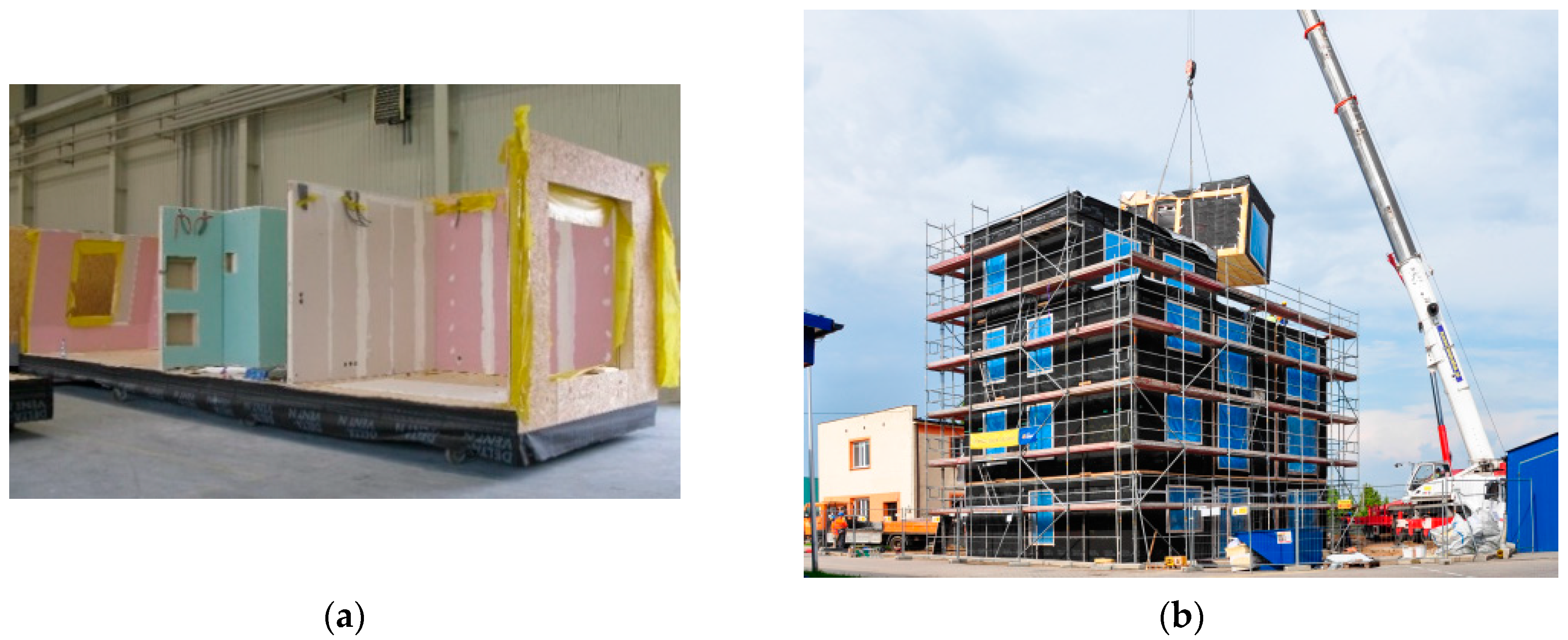
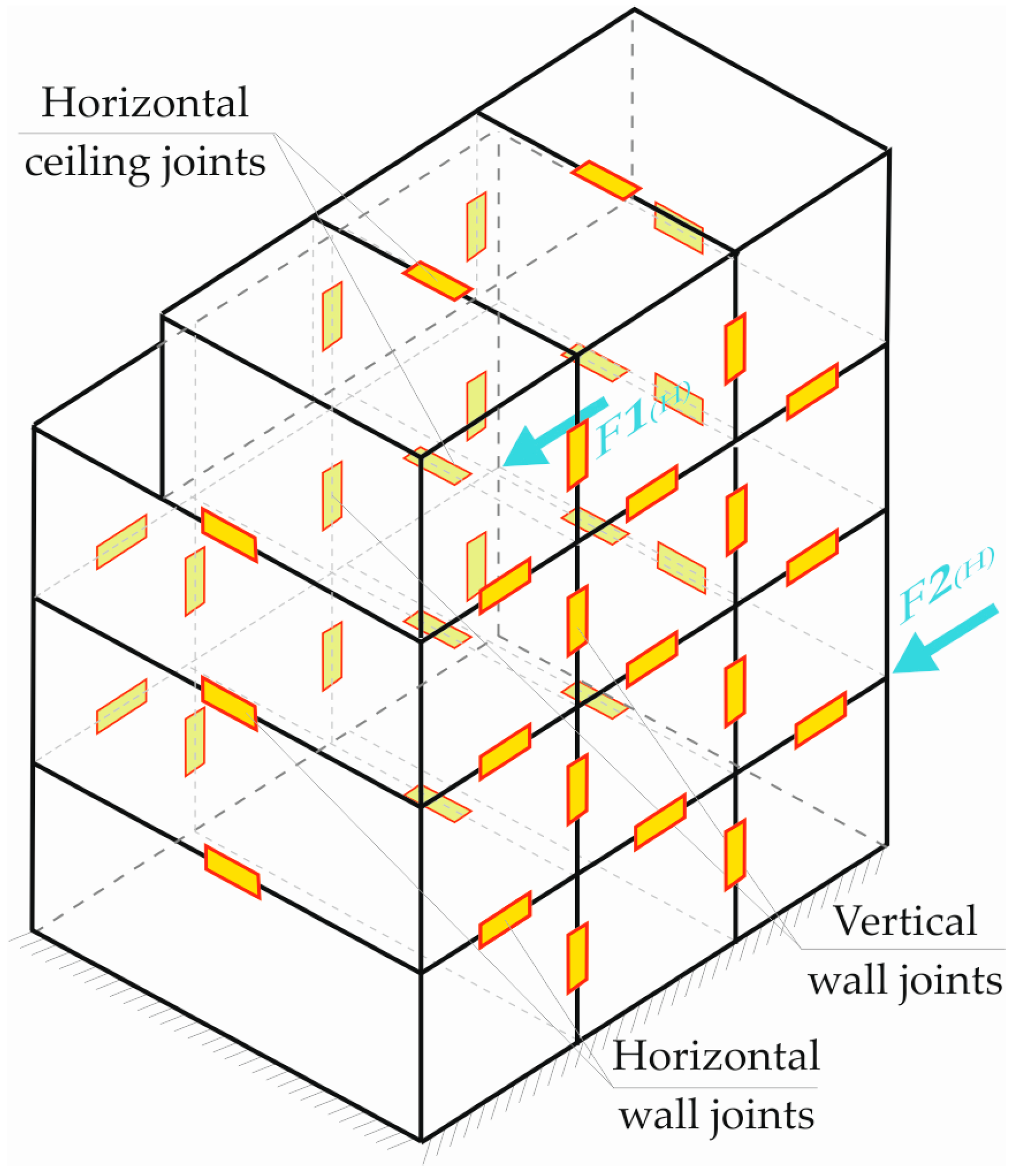
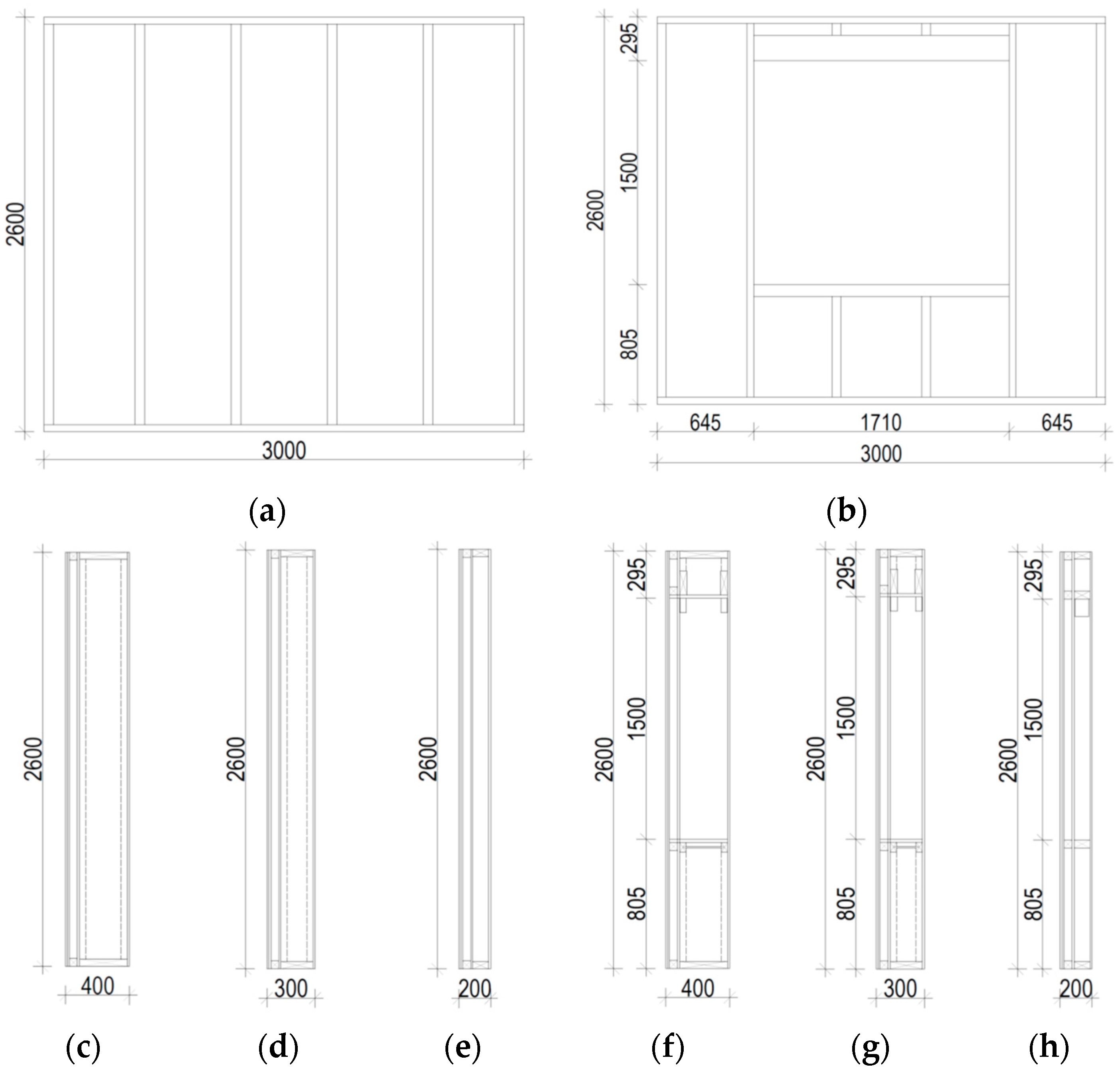
2. Construction of Tested Walls and Building
- -
- type 1: 1.53 × 50 mm staples, with 70 mm spacing;
- -
- type 2: 1.53 × 50 mm staples, with 120 mm spacing;
- -
- type 3: 3.5 × 35 mm screws, with 70 mm spacing.
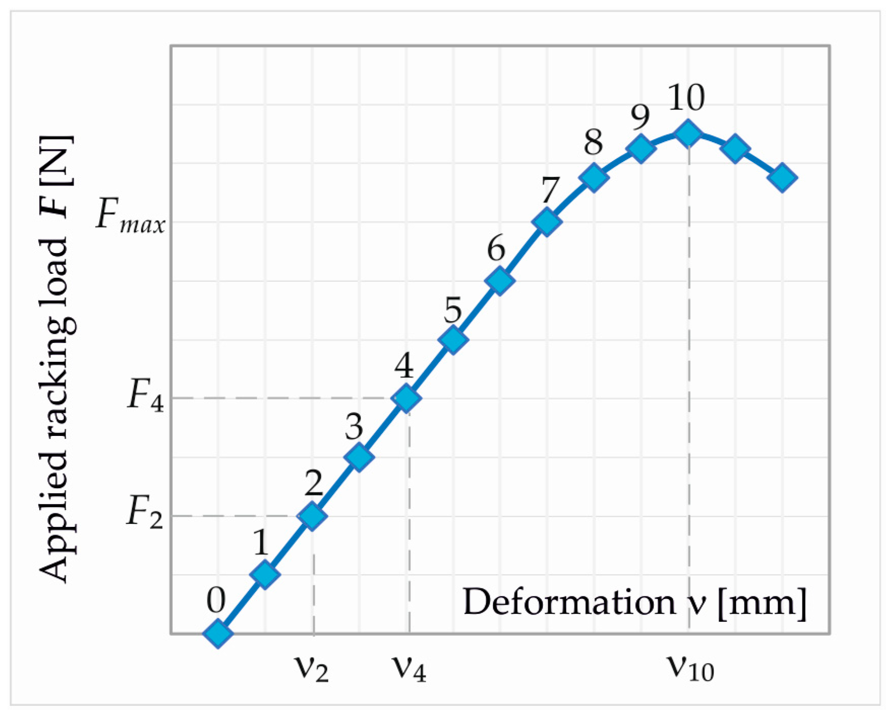
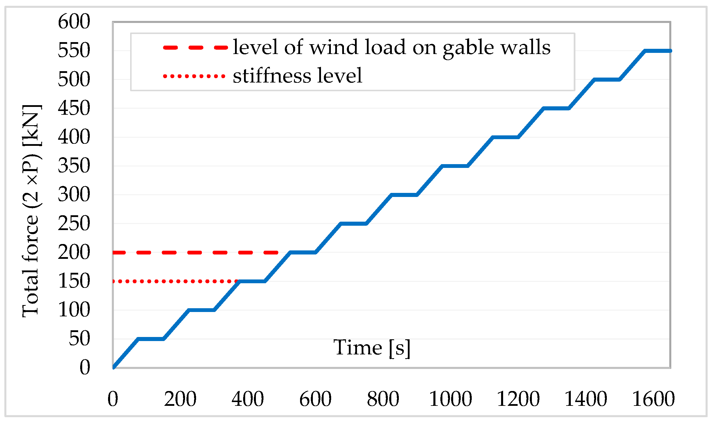
3. Experimental Research Procedures
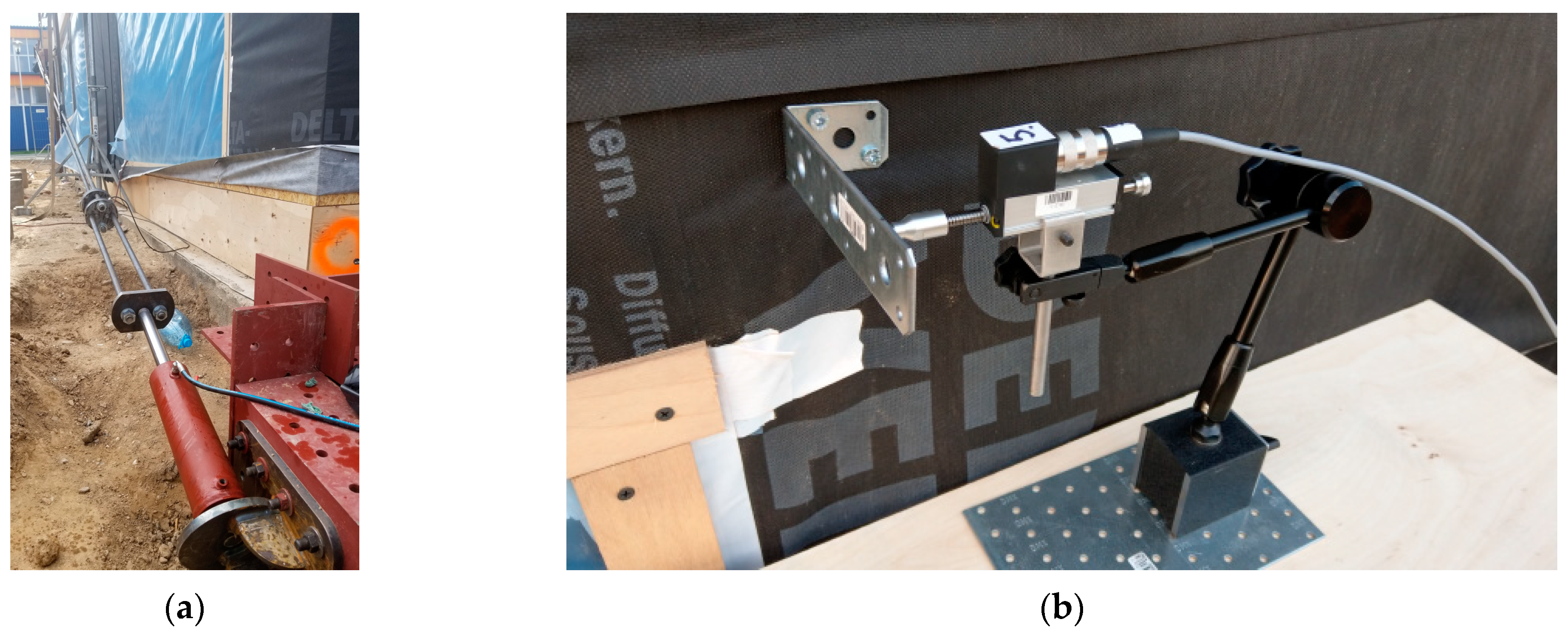
4. Experimental Test Rig and Measuring Equipment
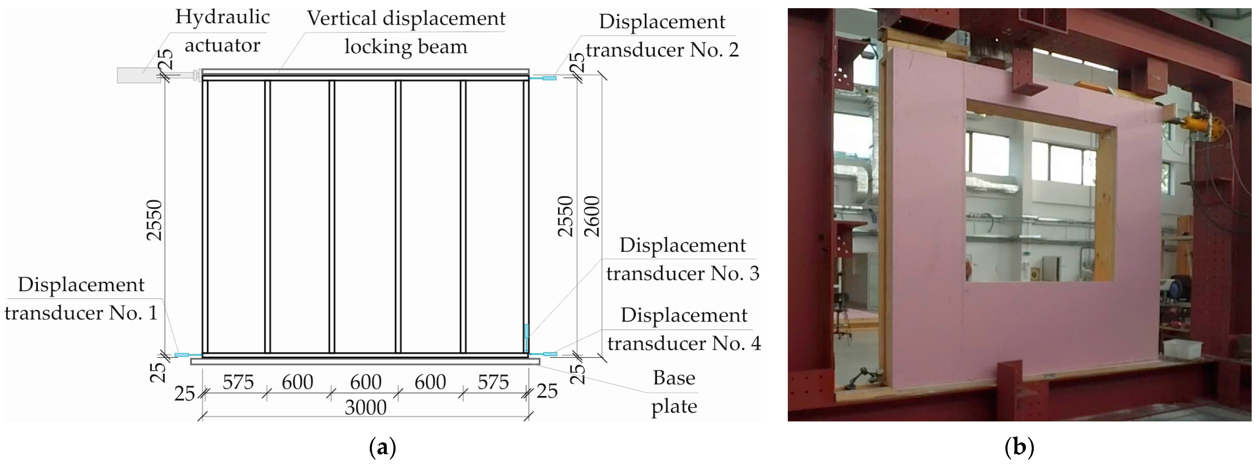
4.1. Wall Panels Tests
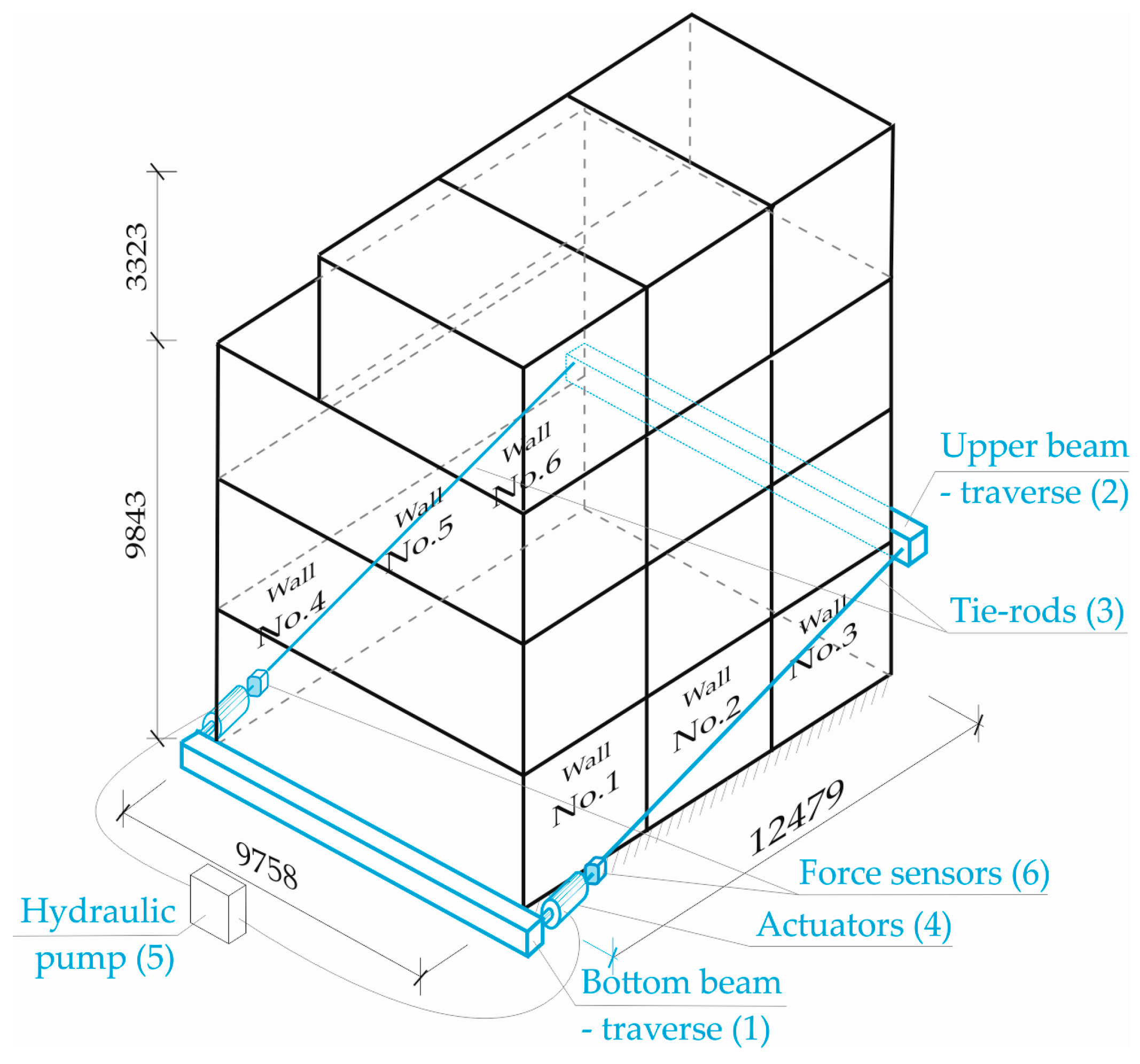
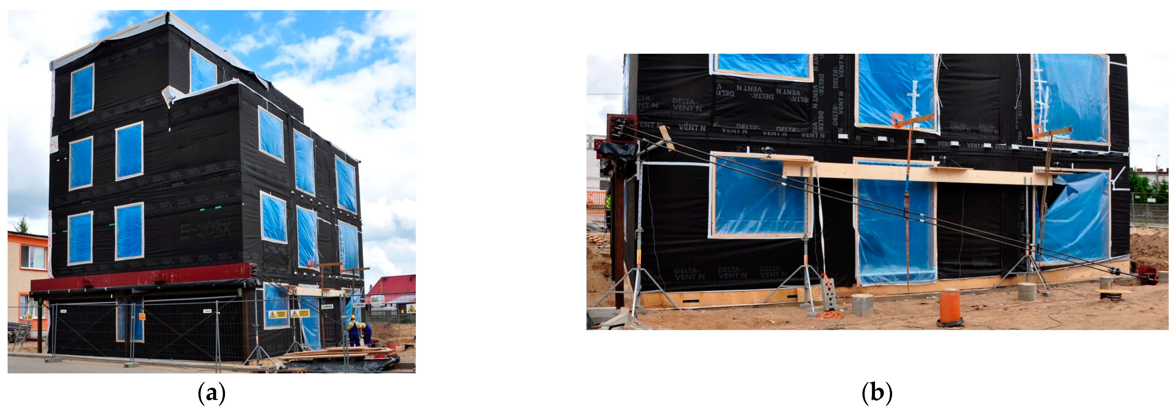
4.2. Building Tests
- type SPR18-25 (MEGATRON Elektronik GmbH & Co. KG, Putzbrunn/Munich, Germany) with a measurement range of 25 mm and linearity tolerance of ±0.2% (4 pieces);
- type SPR18-50 (MEGATRON Elektronik GmbH & Co. KG, Putzbrunn/Munich, Germany) with a measurement range of 50 mm and linearity tolerance of ±0.1% (4 pieces).
5. Test Results
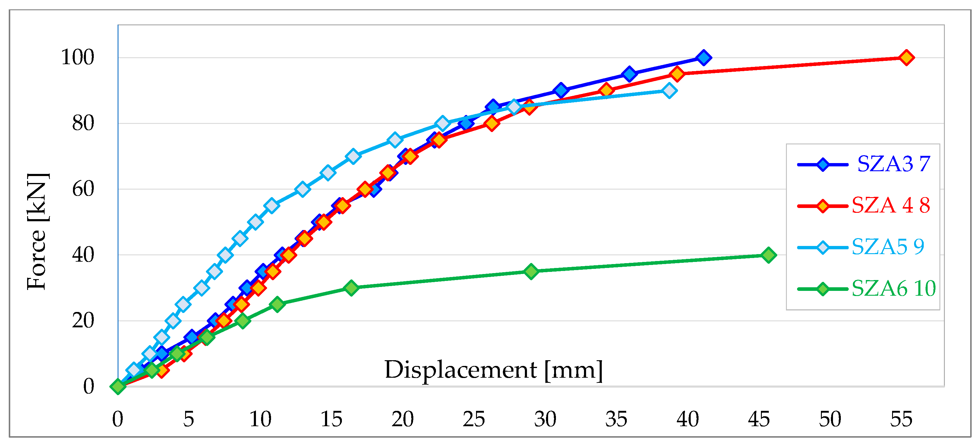
5.1. Test Results for Wall Panels
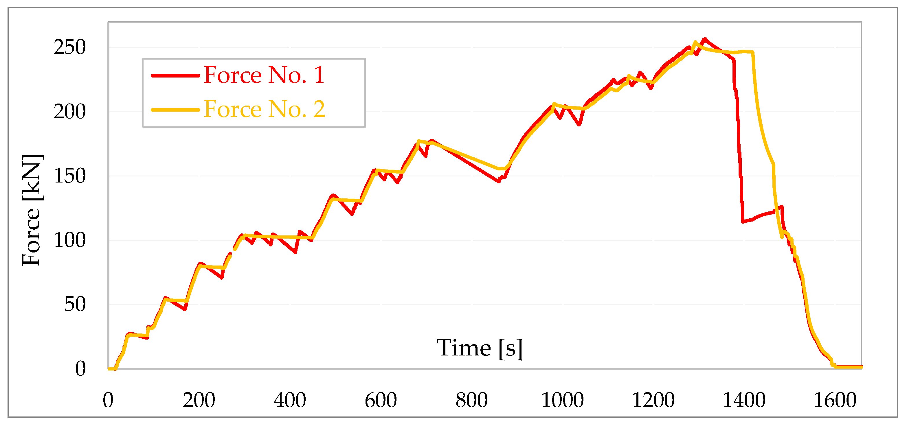
5.2. Building Test Results
6. Discussion
= 986 + 2 · 1577 + 2 · 2913 + 3198 + 1866 + 4264 = 19,294 [N/mm].
7. Conclusions
- the stiffness of the walls is significantly dependent on their configuration and the surfaces of the openings, and ranges from 1715 N/mm to 6186 N/mm;
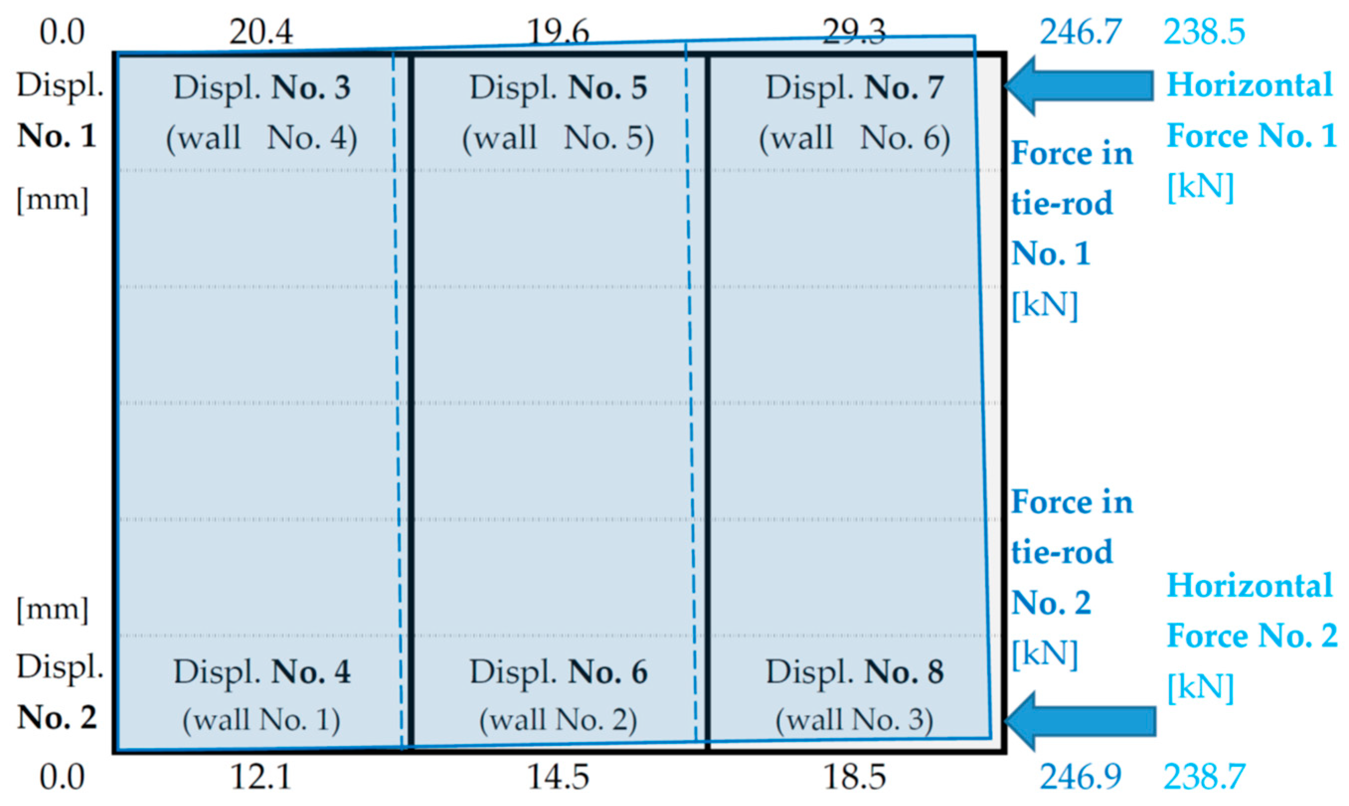
- the walls of the left side of the building with a significantly larger area of openings have a total stiffness 34.0% lower than the total stiffness of the walls of the right side (the reason for the torsion of the building visible in Figure 16);
- the total stiffness of the building walls in the direction of the applied loads (RW = 19,294 N/mm) is 17,200 N/mm less than the spatial stiffness of the building (RB = 36,530 N/mm)—showing how important the influence of the connections between the modules is on the overall stiffness of the building;
- the configuration and location of the walls in the modules influences the nature of the work and deformation of the building and, consequently, the distribution of horizontal loads to the individual walls.
Author Contributions
Funding
Institutional Review Board Statement
Informed Consent Statement
Data Availability Statement
Acknowledgments
Conflicts of Interest
References
- Cameron, P.J., Jr.; Di Carlo, N.G. Piecing Together Modular: Understanding the Benefits and Limitations of Modular Construction Methods for Multifamily Development. Master’s Thesis, Massachusetts Institute of Technology, Cambridge, MA, USA, September 2007. [Google Scholar]
- Szulc, J.; Sieczkowski, J. The Future of Modular Technology in Construction, Design Guide. Inżynier Budownictwa 2020, 5, 82–86. (In Polish) [Google Scholar]
- Malesza, J.; Miedziałowski, C. Current Directions in Development of Modern Wood-framed Houses. In Proceedings of the 12th International Conference on Modern Building Materials, Structures and Techniques (MBMST 2016), Vilnius, Lithuania, 26–27 May 2016. [Google Scholar]
- Nazarczuk, M. Evolution of Timber Structural Systems for Multi-storey Buildings. Civ. Environ. Eng. 2018, 9, 159–166. (In Polish) [Google Scholar]
- Malesza, J.; Baszeń, M.; Miedziałowski, C. Development Directions for Various Types of the Light Wood-Framed Structures. In Proceedings of the IOP Conference Series: Materials Science and Engineering, Tianjin, China, 22–24 September 2017; Institute of Physics Publishing Ltd.: Bristol, UK, 2017. [Google Scholar]
- Knuppe, J. Robustness of Modular Timber Buildings: An Investigation into Alternative Load Paths in Volumetric Timber Post and Beam Modules. Master’s Thesis, Delft University of Technology, Delft, The Netherlands, 2022. [Google Scholar]
- Li, Z.; Tsavdaridis, K.D. Limited-damage 3D-printed Interlocking Connection for Timber Volumetric Structures: Experimental Validation and Computational Modeling. J. Build. Eng. 2023, 63, 105373. [Google Scholar] [CrossRef]
- Kamiya, F. Buckling Theory of Sheathed Walls: Linear Analysis. J. Struct. Eng. 1987, 9, 2009–2022. [Google Scholar] [CrossRef]
- Stewart, A.H.; Goodman, J.R.; Kliewer, A.; Salsbury, E.M. Full Scale Teste of Manufactured Houses under Simulated Wind Loads. In Proceedings of the Conference on Timber Engineering, Forest Products Research Society, Madison, WI, USA, 19–22 September 1988. [Google Scholar]
- Sugyiama, H.; Andoh, N.; Uchisako, T.; Hirano, S.; Nakamura, N. Full Scale Test on Japanes Type of Two–Story Wooden–Frame House Subject to Later Load. In Proceedings of the Conference on Timber Engineering, Forest Products Research Society, Madison, WI, USA, 19–22 September 1988. [Google Scholar]
- Baszeń, M.; Miedziałowski, C.; Malesza, M. Strength Tests of Timber Framed Walls of Buildings. In Proceedings of the XLII Scientific Conference of KILiW PAN and KN PZiTB, Krynica, Poland, 13–18 September 1999. (In Polish). [Google Scholar]
- Kuai, L.; Ormarsson, S.; Vessby, J.; Maharjan, R. A numerical and experimental investigation of non-linear deformation behaviours in light-frame timber walls. Eng. Struct. 2022, 252, 113599. [Google Scholar] [CrossRef]
- Martin, Z.A.; Skaggs, T.D.; Keith, E.L.; Yeh, B. Development of narrow wall bracing and effects of boundary conditions. In Proceedings of the World Conference on Timber Engineering, Portland, OR, USA, 6–10 August 2006. [Google Scholar]
- Šilih, E.K.; Premrov, M. Analysis of timber-framed wall elements with openings. Constr. Build. Mater. 2010, 24, 1656–1663. [Google Scholar] [CrossRef]
- A Standard for Testing Sheathing Materials for Resistance to Racking. Technical Circular No. 12, Federal Housing Administration; Federal Housing Administration: Washington, DC, USA, 1949.
- Miedziałowski, C.; Malesza, M. Timber Frame Buildings with Sheathing. Fundamentals of Structural Mechanics and Issues of Construction and Implementation; Białystok: Warszawa, Poland, 2006. (In Polish) [Google Scholar]
- PN-EN 594:2011; Timber Structures—Test Methods—Testing of Stiffness and Load-Bearing Capacity of Timber-Framed Wall Panels. PKN: Warsaw, Poland, 2011. (In Polish)
- Tuomi, R.L.; McCutheon, J. Testing a Full Scale House under Simulated Snow Loads and Wind Loads; Forest Service Research Paper, FPL 234; Forest Products Laboratory: Madison, WI, USA, 1974. [Google Scholar]
- Boughton, G.N.; Reardon, G.F. Testing a High–Set House Designed for 42 m/s Winds; Technical Report No. 19; Cyclone Testing Station, James Cook University: Townsville, Australia, 1983. [Google Scholar]
- Boughton, G.N.; Parackal, K.; Satheeskumar, N.; Henderson, D.J. Development of a Full-Scale Structural Testing Program to Evaluate the Resistance of Australian Houses to Wind Loads. Front. Built Environ. 2017, 3, 21. [Google Scholar] [CrossRef]
- Collins, M.; Kasal, B.; Paevere, P.; Foliente, G.C. Three-Dimensional Model of Light Frame Wood Buildings. Model Description. J. Struct. Eng. 2005, 131, 676–683. [Google Scholar] [CrossRef]
- Malesza, J.; Miedziałowski, C.; Ustinovičius, L. Tests on Full-Scale and Static Analysis Models of the Wood-Framed Building Structure Horizontaly Loaded. J. Civ. Eng. Manag. 2017, 23, 814–823. [Google Scholar] [CrossRef]
- Smith, I.; Asiz, A.; Gupta, G. High Performance Modular Wood Construction Systems; Final Report No UNB5, Value-to-Wood Program; Natural Resources Canada: Ottawa, ON, Canada, 2007. [Google Scholar]
- Ormarsson, S.; Johansson, M. Finite Element Simulation of Global Structural Behaviour of Multifamily Timber Buildings Using Prefabricated Volume Modules. In Proceedings of the World Conference on Timber Engineering, Seoul, Republic of Korea, 20–23 August 2018. [Google Scholar]
- Ormarsson, S.; Vessby, J.; Johansson, M.; Kua, L. Numerical and Experimental Study on Modular-Based Timber Structures. In Proceedings of the Modular and Offsite Construction (MOC), Banff, AB, Canada, 21–24 May 2019. [Google Scholar]
- Montaño, J.; Almazán, J.L.; Santa María, H. Technical Feasibility Study for the Construction of Modular Light Wood-frame Prefabricated Buildings of Six-story at High Seismic Risk Regions. In Proceedings of the World Conference on Timber Engineering, Seoul, Republic of Korea, 20–23 August 2018. [Google Scholar]
- Popovski, M.; Gavrić, I.; Schneider, J. Performance of Two-storey CLT House Subjected to Lateral Loads. In Proceedings of the 13th World Conference on Timber Engineering, Quebec, QC, Canada, 10–14 August 2014. [Google Scholar]
- Cecotti, A. New Technologics for Construction of Medium-rise Buildings in Seismic Regions: The XLAM case. Struct. Eng. Int. 2008, 18, 156–165. [Google Scholar] [CrossRef]
- Ceccotti, A.; Sandhaas, C.; Okabe, M.; Yasumura, M.; Minowa, C.; Kwai, N. SOFIE project-3D shaking table test on a seven-storey full-scale cross-laminated timber building. Earthq. Eng. Struct. Dyn. 2013, 42, 2003–2021. [Google Scholar] [CrossRef]
- Lacey, A.W.; Chen, W.; Hao, H.; Bi, K. Structural response of modular buildings—An overview. J. Build. Eng. 2018, 16, 45–56. [Google Scholar] [CrossRef]
- Cowled, C.J.L.; Slattery, T.P.; Crews, K.; Brooke, H. Influence of Plasterboard on the Structural Performance of Timber-framed Shear Walls. In Proceedings of the World Conference on Timber Engineering (WCTE 2023), Oslo, Norway, 19–22 June 2023. [Google Scholar] [CrossRef]
- Valdivieso, D.; Lopez-Garcia, D.; Montaño, J.; Guindos, P. Testing of Strong Multi-Layered Wood Frame Shear Walls with Non-Structural Layers. In Proceedings of the World Conference on Timber Engineering (WCTE 2023), Oslo, Norway, 19–22 June 2023. [Google Scholar] [CrossRef]
- Kuai, L.; Ormarsson, S.; Vessby, J. Nonlinear FE-analysis and Testing of Light-frame Timber Shear Walls Subjected to Cyclic Loading. Constr Build Mater. 2023, 362, 129646. [Google Scholar] [CrossRef]
- Abrahamsen, R.; Bjertnćs, M.A.; Bouillot, J.; Brank, B.; Cabaton, L.; Crocetti, R.; Flamand, O.; Garains, F.; Gavrić, I.; Germain, O.; et al. Dynamic Response of Tall Timber Buildings Under Service Load—The DynaTTB Research Program. In Proceedings of the XI International Conference on Structural Dynamics (EURODYN 2020), Athens, Greece, 22–24 June 2020. [Google Scholar] [CrossRef]
- Amaddeo, C.; Dorn, M. Ambient Vibration Tests and Modal Analysis of a Six-story Lightweight Timber Frame Building. In Proceedings of the World Conference on Timber Engineering (WCTE 2023), Oslo, Norway, 19–22 June 2023. [Google Scholar] [CrossRef]
- Designer’s Guide; Unihouse SA: Bielsk Podlaski, Poland, 2020. (In Polish)
- Komorowski, M. Handbook for Designing and Building in STEICO. Fundamentals. Building Physics: Implementation Recommendations; Forest Comunication: Warszawa, Poland, 2018. (In Polish) [Google Scholar]
- Nazarczuk, M. Testing the Stiffness and Load-bearing Capacity of Wall Panels in Timber-framed Buildings in Different Geometric and Structural Configurations. Civ. Environ. Eng. 2018, 9, 131–136. (In Polish) [Google Scholar]
- Miedziałowski, C.; Czech, R.K.; Chyży, T.; Grygo, R.; Nazarczuk, M.; Wasilewski, A.; Żakowicz, A. Test Report on the Transfer of Horizontal Loads in the Ceiling Segments above the Ground Floor in a Timber Frame Modular Building with an Assessment of the Degree of Horizontal Load Transfer; Unihouse & Bialystok University of Technology: Białystok, Poland, 2018. (In Polish) [Google Scholar]


| No. of Wall Panel | Fmax [kN] | F2 [kN] | F4 [kN] | ν2 [mm] | ν4 [mm] | R [N/mm] |
|---|---|---|---|---|---|---|
| SZA3 7 | 100 | 20 | 40 | 6.85 | 11.54 | 4264 |
| SZA6 10 | 40 | 8 | 16 | 4.15 | 6.26 | 3791 |
| SZB6 14 | 55 | 11 | 22 | 7.60 | 12.35 | 2316 |
| SZD4 16 | 120 | 24 | 48 | 10.52 | 18.76 | 2913 |
| SZD5 17 | 145 | 29 | 58 | 8.99 | 16.67 | 3776 |
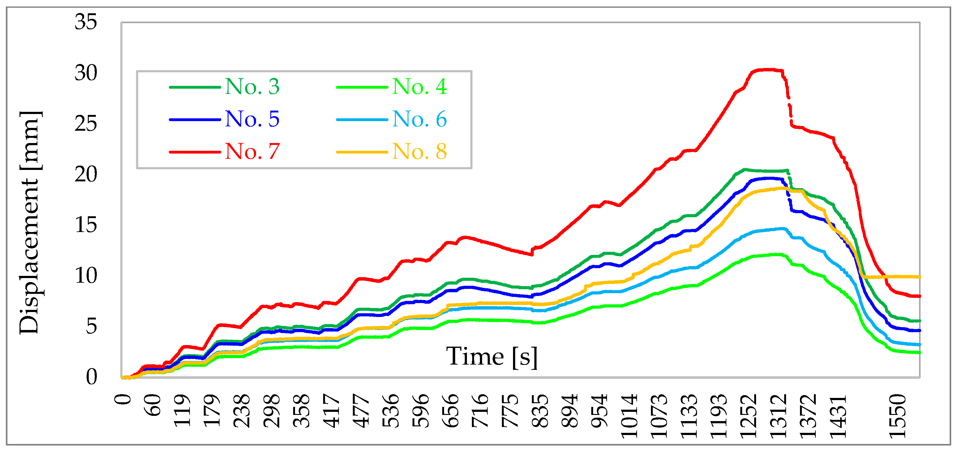
| Force in Tie Rod F1 [kN] | Horizontal Force F1,H [kN] | Horizontal Displacement [mm] | ||
|---|---|---|---|---|
| No. 3 | No. 5 | No. 7 | ||
| 0 | 0.0 | 0 | 0 | 0 |
| 26.7 | 25.8 | 0.85 | 0.78 | 1.12 |
| 53.7 | 51.9 | 2.12 | 1.99 | 3.02 |
| 79.6 | 76.9 | 3.59 | 3.32 | 5.16 |
| 102.4 | 99.0 | 4.91 | 4.54 | 7.09 |
| 131.3 | 126.9 | 6.73 | 6.18 | 9.72 |
| 153.5 | 148.4 | 8.11 | 7.47 | 11.60 |
| 176.1 | 170.2 | 9.42 | 8.63 | 13.37 |
| 204.6 | 197.8 | 12.05 | 11.01 | 16.98 |
| 225.1 | 217.6 | 15.41 | 13.99 | 21.56 |
| 246.7 | 238.5 | 20.36 | 19.62 | 29.30 |
| Force in Tie Rod | Horizontal Force | Horizontal Displacement [mm] | ||
|---|---|---|---|---|
| F2 [kN] | F2,H [kN] | No. 4 | No. 6 | No. 8 |
| 0 | 0.0 | 0 | 0 | 0 |
| 26.3 | 25.4 | 0.49 | 0.53 | 0.51 |
| 53.5 | 51.7 | 1.23 | 1.46 | 1.46 |
| 79.5 | 76.8 | 2.07 | 2.30 | 2.46 |
| 103 | 99.6 | 2.98 | 3.65 | 3.77 |
| 131.6 | 127.2 | 3.99 | 4.60 | 4.84 |
| 153.8 | 148.7 | 4.86 | 5.70 | 6.10 |
| 175.5 | 169.6 | 5.54 | 6.68 | 7.15 |
| 203.8 | 197.0 | 6.95 | 8.36 | 9.28 |
| 225.1 | 217.6 | 8.81 | 10.54 | 12.28 |
| 246.9 | 238.7 | 12.05 | 14.51 | 18.46 |
| Part of the Building | Fmax [kN] | F2 [kN] | F4 [kN] | v2 [mm] | v4 [mm] | R [N/mm] |
|---|---|---|---|---|---|---|
| Left side walls | 238.5 | 51.9 | 99.0 | 2.37 | 5.50 | 15,048 |
| Right side walls | 238.7 | 51.7 | 99.6 | 1.40 | 3.50 | 22,810 |
| All walls/entire building | 477.2 | 103.6 | 198.6 | 1.88 | 4.50 | 36,530 |
Disclaimer/Publisher’s Note: The statements, opinions and data contained in all publications are solely those of the individual author(s) and contributor(s) and not of MDPI and/or the editor(s). MDPI and/or the editor(s) disclaim responsibility for any injury to people or property resulting from any ideas, methods, instructions or products referred to in the content. |
© 2023 by the authors. Licensee MDPI, Basel, Switzerland. This article is an open access article distributed under the terms and conditions of the Creative Commons Attribution (CC BY) license (https://creativecommons.org/licenses/by/4.0/).
Share and Cite
Miedziałowski, C.; Czech, K.R.; Nazarczuk, M.; Kosior-Kazberuk, M.; Żakowicz, A. Stiffness of Experimentally Tested Horizontally Loaded Walls and Timber-Framed Modular Building. Materials 2023, 16, 6229. https://doi.org/10.3390/ma16186229
Miedziałowski C, Czech KR, Nazarczuk M, Kosior-Kazberuk M, Żakowicz A. Stiffness of Experimentally Tested Horizontally Loaded Walls and Timber-Framed Modular Building. Materials. 2023; 16(18):6229. https://doi.org/10.3390/ma16186229
Chicago/Turabian StyleMiedziałowski, Czesław, Krzysztof Robert Czech, Marta Nazarczuk, Marta Kosior-Kazberuk, and Anna Żakowicz. 2023. "Stiffness of Experimentally Tested Horizontally Loaded Walls and Timber-Framed Modular Building" Materials 16, no. 18: 6229. https://doi.org/10.3390/ma16186229
APA StyleMiedziałowski, C., Czech, K. R., Nazarczuk, M., Kosior-Kazberuk, M., & Żakowicz, A. (2023). Stiffness of Experimentally Tested Horizontally Loaded Walls and Timber-Framed Modular Building. Materials, 16(18), 6229. https://doi.org/10.3390/ma16186229