
Impact of an Aluminization Process on the Microstructure and Texture of Samples of Haynes 282 Nickel Alloy Produced Using the Direct Metal Laser Sintering (DMLS) Technique

 , , , and
Abstract
1. Introduction
2. Materials and Methods
Sample Preparation and Thermo-Chemical Treatment
3. Research Results and Discussion
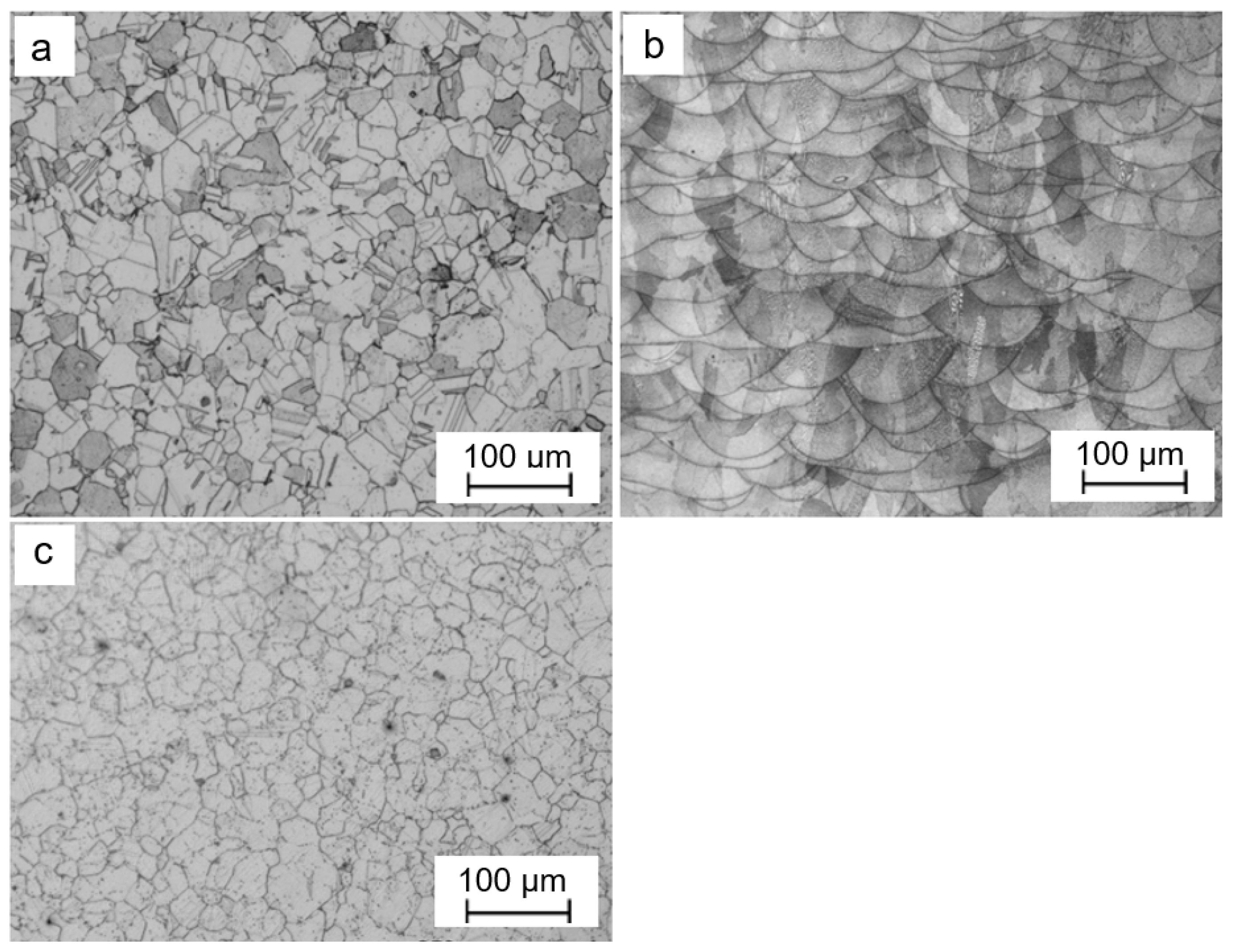
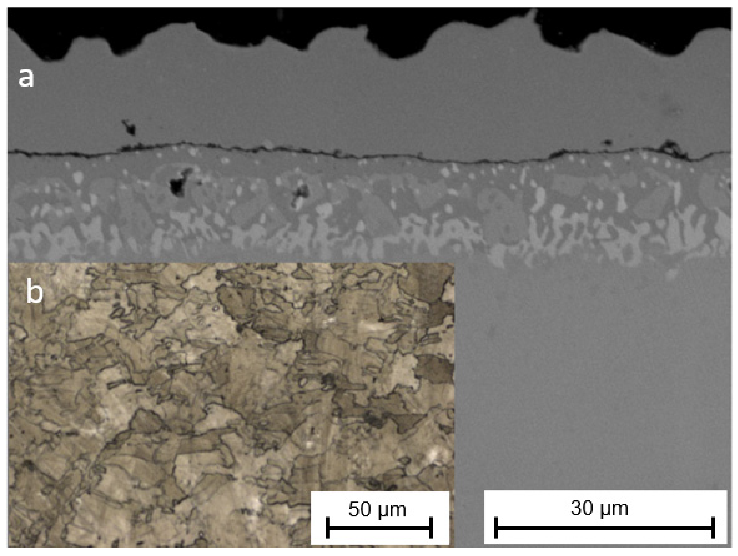
3.1. Microstructure
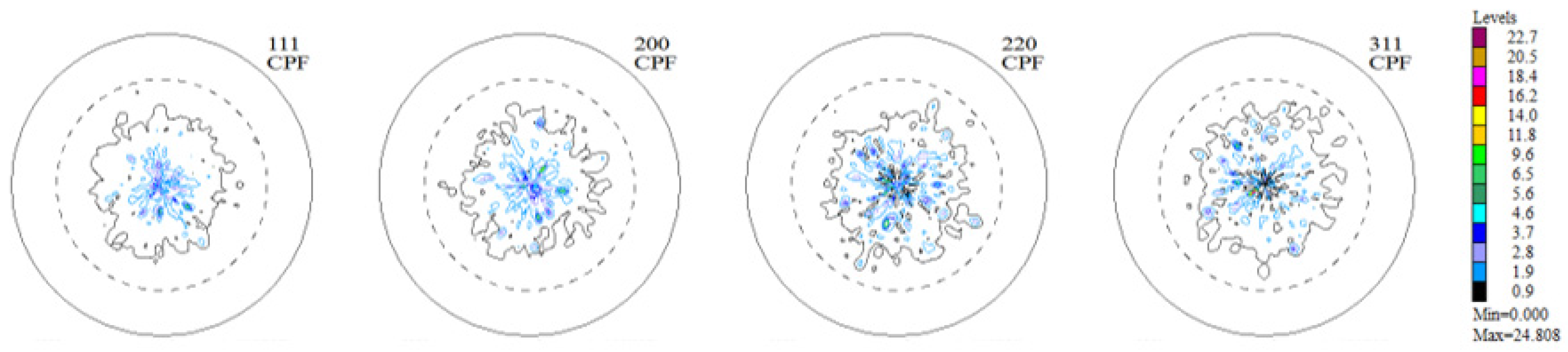
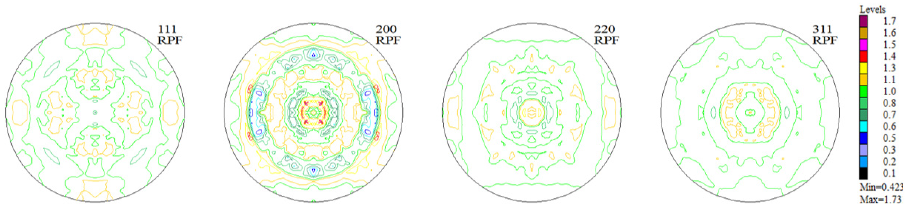
3.2. Texture
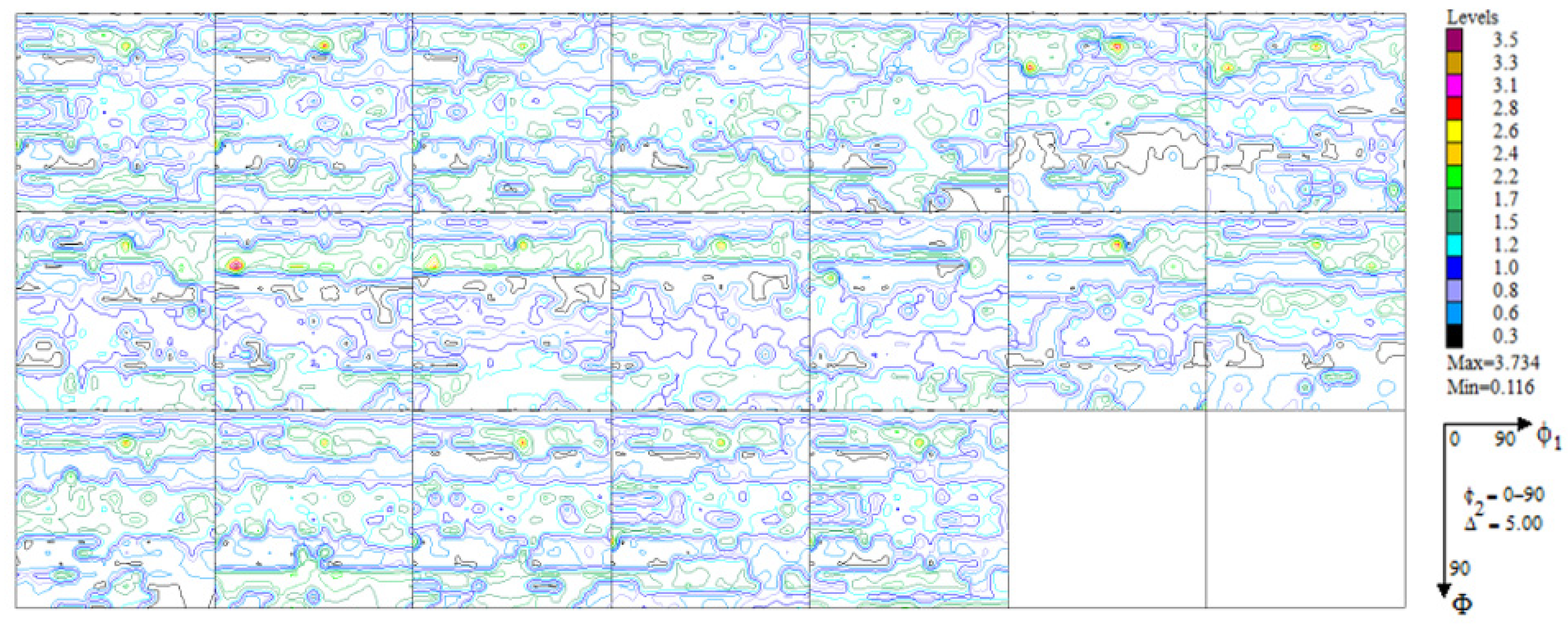
3.2.1. Texture of Haynes 282 Nickel Alloy Samples in the Initial State (as Received from the Producer)
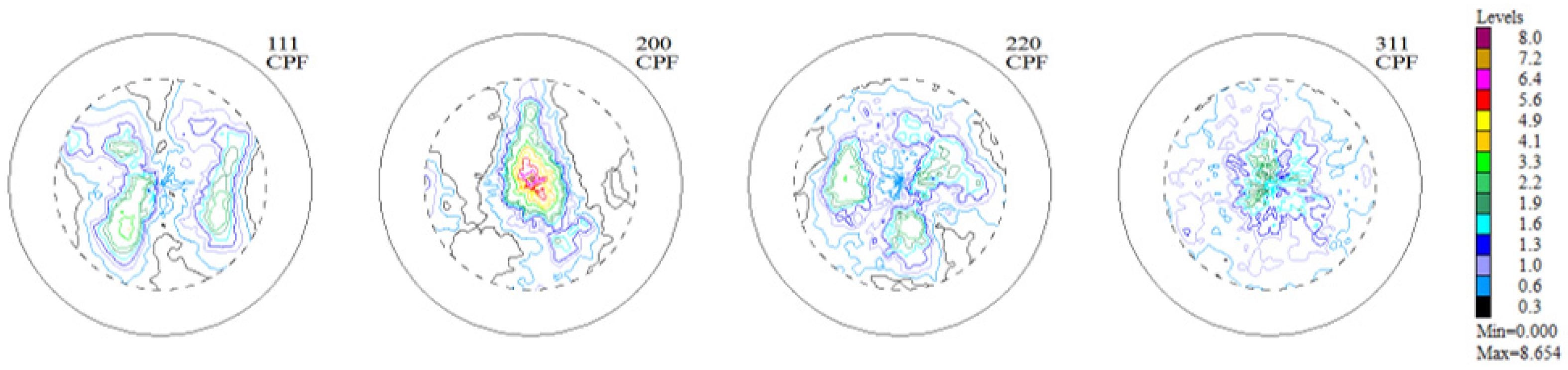
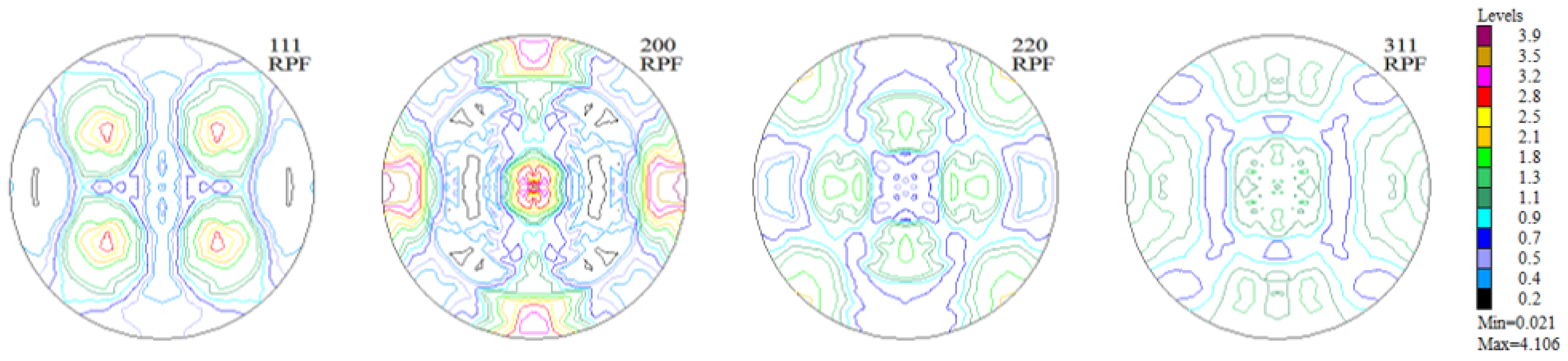
3.2.2. Texture of Samples of Haynes 282 Nickel Alloy Produced Using the DMLS Technique (in the Y-Z Sample Building Plane)
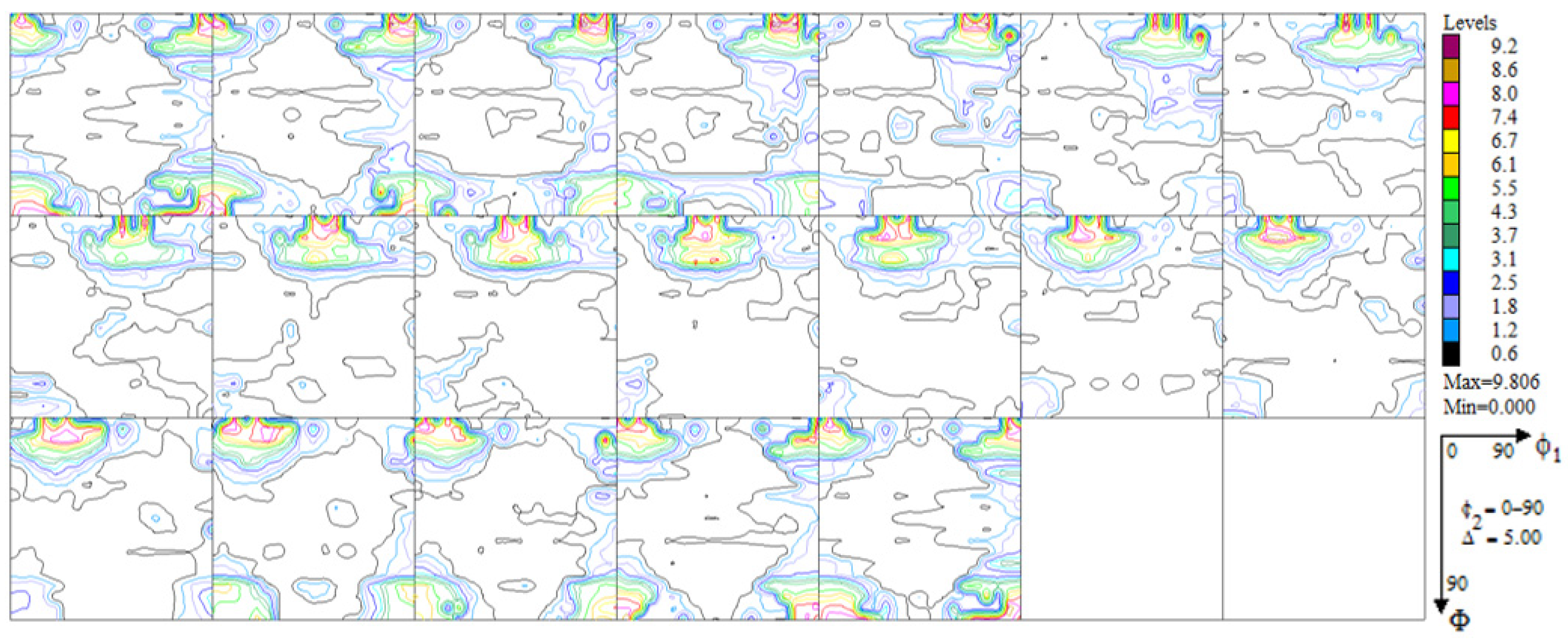
3.2.3. Texture of Samples of Haynes 282 Nickel Alloy Produced Using the DMLS Technique (in the Y-Z Sample Building Plane) and after the Process of Aluminization
4. Conclusions
Author Contributions
Funding
Institutional Review Board Statement
Informed Consent Statement
Data Availability Statement
Conflicts of Interest
References
- Kirka, M.M.; Unocic, K.A.; Kruger, K.; Forsythe, A. Process Development for Haynes® 282® Using Additive Manufacturing; Oak Ridge National Laboratory (ORNL): Oak Ridge, TN, USA, 2018. [Google Scholar] [CrossRef]
- Vattappara, K.; Hosseini, V.A.; Joseph, C.; Hanning, F.; Andersson, J. Physical and thermodynamic simulations of gamma-prime precipitation in Haynes® 282® using arc heat treatment. J. Alloys Compd. 2021, 870, 159484. [Google Scholar] [CrossRef]
- Ko, Y.S.; Kim, B.K.; Jung, W.-S.; Han, H.N.; Kim, D.-I. Effect of the microstructure of Haynes 282 nickel-based superalloys on oxidation behavior under oxy-fuel combustion conditions. Corros. Sci. 2022, 198, 110110. [Google Scholar] [CrossRef]
- Alloy, N.; Tian, Z.; Zhang, C.; Wang, D.; Liu, W.; Fang, X. A Review on Laser Powder Bed Fusion of Inconel 625 Nickel-Based Alloy. Appl. Sci. 2020, 10, 81. [Google Scholar]
- Akhtar, S.; Saad, M.; Misbah, M.R.; Sati, M.C. Recent advancements in powder metallurgy: A review. Mater. Today Proc. 2018, 5, 18649–18655. [Google Scholar] [CrossRef]
- Druzgalski, C.L.; Ashby, A.; Guss, G.; King, W.E.; Roehling, T.T.; Matthews, M.J. Process optimization of complex geometries using feed forward control for laser powder bed fusion additive manufacturing. Addit. Manuf. 2020, 34, 101169. [Google Scholar] [CrossRef]
- Kumar, S. Selective Laser Sintering/Melting. In Comprehensive Materials Processing; Elsevier: Amsterdam, The Netherlands, 2014; pp. 93–134. [Google Scholar] [CrossRef]
- Cabrini, M.; Lorenzi, S.; Testa, C.; Pastore, T.; Brevi, F.; Biamino, S.; Fino, P.; Manfredi, D.; Marchese, G.; Calignano, F.; et al. Evaluation of Corrosion Resistance of Alloy 625 Obtained by Laser Powder Bed Fusion. J. Electrochem. Soc. 2019, 166, C3399–C3408. [Google Scholar] [CrossRef]
- Singh, S.; Andersson, J. Heat-affected-zone liquation cracking in welded cast haynes® 282®. Metals 2020, 10, 29. [Google Scholar] [CrossRef]
- Marchese, G.; Lorusso, M.; Parizia, S.; Bassini, E.; Lee, J.-W.; Calignano, F.; Manfredi, D.; Terner, M.; Hong, H.-U.; Ugues, D.; et al. Influence of heat treatments on microstructure evolution and mechanical properties of Inconel 625 processed by laser powder bed fusion. Mater. Sci. Eng. A 2018, 729, 64–75. [Google Scholar] [CrossRef]
- Jackson, M.P.; Reed, R.C. Heat treatment of UDIMET 720Li: The effect of microstructure on properties. Mater. Sci. Eng. A 1999, 259, 85–97. [Google Scholar] [CrossRef]
- Osoba, L.O.; Khan, A.K.; Adeosun, S.O. Cracking susceptibility after post-weld heat treatment in haynes 282 nickel based superalloy. Acta Metall. Sin. 2013, 26, 747–753. [Google Scholar] [CrossRef]
- Li, C.; White, R.; Fang, X.Y.; Weaver, M.; Guo, Y.B. Microstructure evolution characteristics of Inconel 625 alloy from selective laser melting to heat treatment. Mater. Sci. Eng. A 2017, 705, 20–31. [Google Scholar] [CrossRef]
- Deshpande, A.; Nath, S.D.; Atre, S.; Hsu, K. Effect of post processing heat treatment routes on microstructure and mechanical property evolution of haynes 282 Ni-based superalloy fabricated with selective laser melting (SLM). Metals 2020, 10, 629. [Google Scholar] [CrossRef]
- Song, K.H.; Nakata, K. Effect of precipitation on post-heat-treated Inconel 625 alloy after friction stir welding. Mater. Des. 2010, 31, 2942–2947. [Google Scholar] [CrossRef]
- Sitek, R.; Kaminski, J.; Mizera, J. Corrosion Resistance of the Inconel 740H Nickel Alloy after Pulse Plasma Nitriding at a Frequency of 10 kHz. Acta Phys. Pol. A 2016, 129, 584–587. [Google Scholar] [CrossRef]
- Sitek, R. Influence of the high-temperature aluminizing process on the microstructure and corrosion resistance of the IN 740H nickel superalloy. Vacuum 2019, 167, 554–563. [Google Scholar] [CrossRef]
- Sitek, R.; Molak, R.; Zdunek, J.; Bazarnik, P.; Wiśniewski, P.; Kubiak, K.; Mizera, J. Influence of an aluminizing process on the microstructure and tensile strength of the nickel superalloy IN 718 produced by the Selective Laser Melting. Vacuum 2021, 186, 110041. [Google Scholar] [CrossRef]
- Romanowska, J. Aluminum diffusion in aluminide coatings deposited by the CVD method on pure nickel. CALPHAD Comput. Coupling Phase Diagr. Thermochem. 2014, 44, 114–118. [Google Scholar] [CrossRef]
- Yavorska, M.; Sieniawski, J.; Zielińska, M. Functional properties of aluminide layer deposited on INCONEL 713 LC Ni-based super alloy in the CVD process. Arch. Metall. Mater. 2011, 56, 187–192. [Google Scholar] [CrossRef]


| Texture Component {h k l} <u v w> | Volume Fraction [%] |
|---|---|
| (4 1 1) <2 5 > | 5.0 |
| Background | 95.0 |
| Texture Component {h k l} <u v w> | Volume Fraction [%] |
|---|---|
| (0 0 1) <1 0 0> | 54.0 |
| (4 1 1) <2> | 10.0 |
| Background | 36.0 |
| Texture Component {h k l} <u v w> | Volume Fraction [%] |
|---|---|
| (4 3 1) <3 0> | 27.0 |
| (1 5 3) <0 5> | 23.0 |
| (0 0 1) <2 0> | 14.0 |
| (0 1 1) <0 1 1> | 12.0 |
| 0 1> | 11.0 |
| > | 6.0 |
| Background | 7.0 |
Disclaimer/Publisher’s Note: The statements, opinions and data contained in all publications are solely those of the individual author(s) and contributor(s) and not of MDPI and/or the editor(s). MDPI and/or the editor(s) disclaim responsibility for any injury to people or property resulting from any ideas, methods, instructions or products referred to in the content. |
© 2023 by the authors. Licensee MDPI, Basel, Switzerland. This article is an open access article distributed under the terms and conditions of the Creative Commons Attribution (CC BY) license (https://creativecommons.org/licenses/by/4.0/).
Share and Cite
Mizera, J.; Adamczyk-Cieślak, B.; Maj, P.; Wiśniewski, P.; Drajewicz, M.; Sitek, R. Impact of an Aluminization Process on the Microstructure and Texture of Samples of Haynes 282 Nickel Alloy Produced Using the Direct Metal Laser Sintering (DMLS) Technique. Materials 2023, 16, 5108. https://doi.org/10.3390/ma16145108
Mizera J, Adamczyk-Cieślak B, Maj P, Wiśniewski P, Drajewicz M, Sitek R. Impact of an Aluminization Process on the Microstructure and Texture of Samples of Haynes 282 Nickel Alloy Produced Using the Direct Metal Laser Sintering (DMLS) Technique. Materials. 2023; 16(14):5108. https://doi.org/10.3390/ma16145108
Chicago/Turabian StyleMizera, Jarosław, Bogusława Adamczyk-Cieślak, Piotr Maj, Paweł Wiśniewski, Marcin Drajewicz, and Ryszard Sitek. 2023. "Impact of an Aluminization Process on the Microstructure and Texture of Samples of Haynes 282 Nickel Alloy Produced Using the Direct Metal Laser Sintering (DMLS) Technique" Materials 16, no. 14: 5108. https://doi.org/10.3390/ma16145108
APA StyleMizera, J., Adamczyk-Cieślak, B., Maj, P., Wiśniewski, P., Drajewicz, M., & Sitek, R. (2023). Impact of an Aluminization Process on the Microstructure and Texture of Samples of Haynes 282 Nickel Alloy Produced Using the Direct Metal Laser Sintering (DMLS) Technique. Materials, 16(14), 5108. https://doi.org/10.3390/ma16145108