Abstract
FGH96 is a powder metallurgy Ni-based superalloy used for turbine disks of aero-engines. In the present study, room-temperature pre-tension experiments with various plastic strain were conducted for the P/M FGH96 alloy, and subsequent creep tests were conducted under the test conditions of 700 °C and 690 MPa. The microstructures of the pre-strained specimens after room-temperature pre-strain and after 70 h creep were investigated. A steady-state creep rate model was proposed, considering the micro-twinning mechanism and pre-strain effects. Progressive increases in steady-state creep rate and creep stain within 70 h were found with increasing amounts of pre-strain. Room-temperature pre-tension within 6.04% plastic strain had no obvious influence on the morphology and distribution of γ′ precipitates, although the dislocation density continuously increased with the increase in pre-strains. The increase in the density of mobile dislocations introduced by pre-strain was the main reason for the increase in creep rate. The predicted steady-state creep rates showed good agreement with the experiment data; the creep model proposed in this study could capture the pre-strain effect.
1. Introduction
Powder metallurgy (P/M) Ni-based superalloys have been extensively used as turbine discs in modern aeroplane engines due to their excellent mechanical properties. Due to the high requirements of reliability and durability of turbine discs, creep properties of P/M superalloy are of great importance to the safety of the component [1,2,3,4]. Cold pre-deformation is usually used in engineering practice to control residual stress, to improve dimensional stability, and to improve the low cycle fatigue life of aero-engine discs [5,6]. However, pre-deformation also affects the creep properties of Ni-based superalloys at the same time, which might reduce the creep resistance of the disc material [7,8,9]. Therefore, the influence of pre-deformation on the subsequent high-temperature creep behaviour is a topic of significant theoretical and practical interest.
The influence of pre-deformation on creep properties varies for different metallic materials. The improvements in creep resistance after pre-straining were observed for some polycrystalline Ni-based alloys. For example, Marlin et al. [10] found that the creep rate at 760 °C may decrease with increasing pre-strain at the same temperature for an oxide-dispersion-strengthened Ni-based alloy. Cairney et al. [11] reported that pre-strain at both room temperature and elevated temperatures can decrease the creep strain at 520 °C for single-crystal Ni3Al. However, a contrary effect was also observed in Ni-based superalloys where the minimum creep rates were increased and the creep life was shortened with increasing amounts of pre-strain. Zhang and Knowles [12] reported that the minimum creep rate of a nickel-based C263 superalloy at 800 °C can be slightly enhanced with increasing amounts of room-temperature pre-tension. Dyson [13,14] examined the creep response of Nimonic 80A at 750 °C after room-temperature pre-tension. The results showed that the material suffered progressive losses of creep strength, life, and fracture ductility as pre-strain increased. Concerning the microstructure, pre-strain increased the density of mobile dislocations on the one hand, resulting in an increase in initial creep rate. On the other hand, dislocations induced by pre-strain will increase the resistance to dislocation movement, which may enhance creep resistance [7]. In addition, it is possible to increase dislocation annihilation rates, which may lead to decreases in creep strain [7]. The density of voids in the grain boundary region increases after pre-strain, which has adverse effects on creep life [7,13,15]. Therefore, the influence of pre-strain on the creep behaviour varies with different alloys. This is related to the temperature and amount of pre-strain, the microstructure, creep testing temperature, stress, and the corresponding creep mechanism. It remains necessary to study the pre-strain effects on creep behaviour for the FGH96 alloy under specific creep test conditions.
Most existing creep models that consider the pre-strain effect are phenomenological [16,17,18,19]. For example, the Norton law for creep was modified to relate the model parameters with pre-strain and temperature [17]. A damage tensor controlled by pre-strain was introduced into the creep damage tensor to reflect the accelerating effect of pre-strain on void nucleation at grain boundaries [18]. Pre-strain effect was involved in internal stress to affect the creep behaviours [19]. Creep mechanisms have not explicitly been included in these models; therefore, feasible creep models considering both the creep mechanism and pre-strain effect need to be established to quantify the creep response changes caused by prior plastic deformation.
In this study, pre-tension of the FGH96 superalloy was carried out at room temperature, and creep tests were subsequently conducted. The influence of pre-strain on the steady-state creep rates and the influencing mechanism are discussed. Based on the micro-twinning mechanism, a calculation model for the steady-state creep rate was established with the pre-strain effect involved. The numerical results were compared with experimental data to verify the effectiveness of the model.
2. Materials and Methods
The chemical composition (in wt. %) of the FGH96 alloy was: 12.9% Co, 15.7% Cr, 4% Mo, 4% W, 2.1% Al, 3.7% Ti, 0.7% Nb, 0.05% C, 0.03% B, 0.05% Zr, and balanced Ni. The FGH96 alloys were prepared using the powder metallurgy method. The powders were consolidated by hot isostatic pressing (HIP) (1100–1200 °C,120–140 MPa, 3–5 h). Then, the HIPed ingot was hot-extruded and isothermally forged at subsolvus temperatures. After forging, the pancake was heat-treated at 1160 °C for 4 h to obtain a solid solution, and then aged at 760 ℃ for 16 h followed by air cooling.
Uniaxial creep test specimens were subsequently cut from the aged ingot along tangential direction and machined to the specimen dimension (Figure 1). Then, the creep test specimen was pre-strained at room temperature using an INSTRON tensile machine at a crosshead speed of 0.25 mm/min. An extensometer was used to measure the strain during loading and unloading of the tension process. The measured plastic strains after pre-tension were 0.33%, 0.34% 0.35%, 0.43%, 0.47%, 0.48%, 0.60%, 0.61%, 0.63%, 1.01%, 1.05%, 3.01%, and 6.04%, respectively. After pre-tension, the creep tests were carried out at 700 °C and 690 MPa with a duration time of 70 h.

Figure 1.
Dimensional drawing of the creep test specimen (unit: mm).
The metallographic structure was observed by optical microscopy (OM) and the distribution of γ′ precipitates was examined by scanning electron microscopy (SEM: LEO Gemini 1525) before and after pre-tension. The SEM samples were ground, polished, and electro-etched at 3.5 V, 2 A for one second at room temperature. Transmission electron microscopy (TEM) observation foils were sliced from the standard gauge area of the creep test specimen sectioned 90° to the stress axis. The foils were prepared by twin-jet thinning in a solution of 10 vol% HClO4 + 90 vol% C2H5OH at −20 °C. The microstructure of pre-strained and 70 h crept specimens was examined using a JEOL JEM 2100F electron microscope with an operating voltage of 200 kV.
3. Creep Model with Pre-Strain Effect
3.1. Micro-Twinning-Based Creep Model
Previous studies [1,2,3,4,20,21] on FGH96 superalloys indicated that slip-induced micro-twinning was the dominate creep mechanism at creep temperatures of 650–750 °C and stress of 690–810 MPa. Therefore, the micro-twinning mechanism was considered in the creep model.
According to the micro-twinning mechanism [22], after the movements of two a/6<112> partial dislocations, twins were induced in the γ matrix and pseudo-twins (PTs) were induced in the secondary γ′ matrix. The PTs exhibited an orthorhombic structure which involved Al–Al nearest neighbours, are differently from those remaining in the secondary γ′ with the L12 structure. These PTs have high energies and impede the movements of a/6<112> dislocations. Diffusion-mediated reordering near the {111} planes yielded twinned parts with the ideal L12 structure. The rearranged atomic lattice formed a mirror-image relationship with the original lattice before the PT formation, which meant that true twins (TT) were formed. The transformation from high-energy PTs to low-energy TTs made the a/6<112> dislocations slip again, leading to continuous creep deformation. Therefore, the formation of PTs was induced by the shear of dislocations, while the formation of TTs is thermally mediated.
As shown in Figure 2, in order to establish the theoretical creep model, it was assumed that the secondary γ′ had a cubic morphology and was uniformly distributed in the γ matrix; the tertiary γ′ was ignored due to its much smaller size and lower volume fraction. The energy for the formation of twins in the matrix in a unit cell is expressed as:
where is the formation energy of two-layer true twins in matrix, is the cubic length of the secondary γ′, and L is the length of the unit cell.
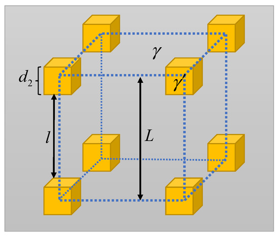
Figure 2.
Illustrations of the γ matrix and secondary γ′.
The energy for the formation of twins in the secondary γ′ consisted of two parts. One was the energy for the formation of true twins, written as
where is the formation energy of the two-layer true twins. The other one is the energy required for reordering to accomplish the transformation from PTs to TTs, , which can be related to the time needed for the formation of true twins, expressed as [23,24]:
where , is the formation energy for the two-layer PTs. K denotes the reordering rate expressed as , with being the diffusion coefficient for the reordering and x being the short range diffusion length, usually obtained as , where is the magnitude of the Burgers vector [23,24].
Similarly to the model developed by Karthikeyan et al. [25], considering the movements of a/6<112> dislocations in two-layer {111} planes, the energy balance at the steady-state stage can be expressed as:
where is the effective resolved shear stress in a α slip system. The above equation indicates that the work performed by external force is used for the formation of true twins in matrix and secondary γ′, and the energy for the reordering. The energy for reordering should be positive; therefore, a requirement for the stress is written as , which is also equivalent to with .
Combining Equations (1)–(4) yields:
Using the Orowan equation [26], the shear rate is expressed as [25]
where is the mobile dislocation density, and is the average dislocation velocity which is obtained considering the time for the formation of true twins in secondary γ′ and ignoring the time for dislocation slip.
Combining Equations (5) and (6), the shear rate is obtained as:
If the dislocation density is assumed to be unchanged in the steady-state creep stage, the shear rate can be expressed as:
where is the initial shear rate, which is related to the initial dislocation density ().
For uniaxial creep, considering multiple slip, the relationship between uniaxial creep rate and shear rate can be written as [27,28]:
where M is the Taylor factor [29].
In addition, the resolved shear stress can be expressed as [29,30]:
where denotes the uniaxial stress.
Combining Equations (8)–(10), the uniaxial creep rate is obtained as:
The above equation relates the steady-state creep rate to the uniaxial stress. The strain rate is proportional to the initial density a/6<112> partial dislocations and average diameter of secondary γ′.
3.2. Creep Model with Pre-Strain Effect
In order to capture the increase in mobile dislocation density with the increase in pre-strain, the Kocks–Mecking [31,32] relationship was adopted to describe the evolution of dislocation densities with time, considering the working hardening and dynamic recovery mechanisms, expressed as [33]:
where is the dislocation density, is the applied strain, and M is the Taylor factor. k1 is a temperature-independent parameter reflecting the dislocation accumulation, and k2 is a temperature-dependent parameter describing the dislocation annihilation [34].
Assuming that the dislocation density can be uniquely determined by pre-strain in the pre-tension process, the relationship between dislocation density and pre-strain can be obtained by integrating Equation (12), and is written as:
Combining Equations (11) and (13), the steady-state creep rate model with the pre-strain effect could be given as:
where denotes the pre-strain, and is the mobile dislocation density without pre-strain.
4. Result and Discussion
4.1. Influence of Pre-Strain on the Creep Behaviour
Figure 3a shows the creep strain curve of specimens with different amount of pre-strain. It can be seen that the 70 h creep strain continuously increased with the increase in pre-strain. For specimens with the same amount of pre-strain, the 70 h creep strain exhibited certain dispersity, which might be caused by the variations in the microstructure and internal stress of the specimen. The amount of creep strain at the primary stage and the duration of primary creep stage increased with the increase in pre-strain, while the steady-state stage still dominated. Compared with that of the unstrained specimen, the creep strain of pre-strained specimens accumulated rapidly in the first few hours, and then crept at a higher steady-state rate. For the specimen with 6.04% pre-strain, the creep strain exceeded 0.2% in the first 5 h, far more than the creep strain after 70 h of specimens that had pre-strain less than 0.6%.
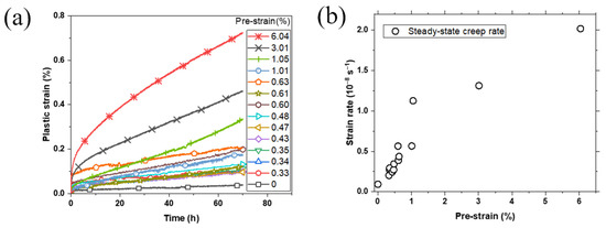
Figure 3.
(a) Creep curves and (b) steady-state creep rates at 700 °C/690 MPa.
As shown in Figure 3b, the steady-state creep rate increased with the increasing amount of pre-strain. Even a small amount of pre-strain had a clear impact on the steady-state creep rate, indicating that the creep rate of FGH96 alloy at 700 °C/690 MPa was sensitive to room-temperature pre-strain. For the specimen with 3% pre-strain, the steady-state creep rate was more than 10 times greater than that of unstrained specimen, which means that a large amount of pre-strain will result in a significant loss of creep resistance.
4.2. Influence of Pre-Strain on Microstructure
The grain morphology and distribution of γ′ precipitates before and after pre-tension are shown in Figure 4. The unstrained and 6.04% pre-strained specimens had a similar grain morphology with an average grain size of approximately 40 μm. The morphology and distribution of both secondary γ′ and tertiary γ′ showed no obvious differences. Most of the secondary γ′ particles were spherical or cuboid in shape, with concave faces, similarly to the results of previous studies [4,35]. For unstrained and 6.04% pre-strained specimens, the volume fractions of secondary γ′ of were 39% and 41%, and the average diameters were 162 nm and 148 nm, respectively. This indicated that room-temperature pre-tension within 6.04% plastic strain had no obvious influence on the morphology and distribution of γ′ precipitates.

Figure 4.
The grain morphology (a,b) and γ′ distribution (c,d) of FGH96 before and after pre-strains: (a) OM unstrained, (b) OM 6.04% pre-strained, (c) SEM unstrained, and (d) SEM 6.04% pre-strained.
Figure 5 shows the dislocation distribution in the FGH96 alloy after various degrees of room-temperature pre-strain. After 0.33% pre-strain, independent dislocations appeared, and the dislocations were mainly located in the matrix (Figure 5b). After 1.01% pre-strain, a large number of dislocations were found both in the matrix and the γ′/γ interface (Figure 5c). The dislocation density was much higher than that of the 0.33% pre-strained specimen. When the pre-strain reached 6.04%, continuous dislocation lines appeared and the dislocation lines were parallelly distributed (Figure 5d). At this point, significant plastic deformation and strain strengthening occurred. The dislocation density inside the alloy significantly increased.
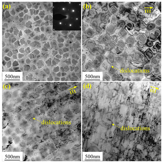
Figure 5.
TEM analysis of the FGH96 alloy after various degrees of pre-strains: (a) un-strained, (b) 0.33% pre-strain, (c) 1.01% pre-strain, and (d) 6.04% pre-strain.
The creep deformation of the Ni-based superalloy involved two parts: dislocation slipping in the matrix channel and dislocation cutting through γ′ particles. In the primary stage of creep, creep deformation was mainly provided by dislocation slip in the matrix channel. The change in dislocation density under different amounts of pre-strain will affect the creep behaviour of FGH96 alloys to varying degree. For the 0.3% pre-strained specimen, pre-strain-induced dislocations slipped in the matrix channel at the beginning of creep. Compared with the unstrained specimen, the existence of pre-strain-induced dislocations reduced the time for dislocation formation and accelerated the progression of dislocation slip in the primary creep stage. For specimens with 1.01% and 6.04% pre-strain, the mobile dislocation densities increased significantly, which further accelerated dislocation movement and increased the strain rate during primary creep stage. In addition, the release of misfit stress, caused by the formation of interface dislocations during room-temperature pre-deformation, could reduce the hindrance to dislocation movement to some extent. This might also be a factor contributing to the increase in creep rate.
According to the Orowan equation [26], two competing effects can be introduced by pre-strain in terms of the creep strain rate. On the one hand, the dislocation density induced by room-temperature pre-strain impedes dislocation movement, thereby reducing the average moving velocity of dislocations and resulting in a decrease in creep rate, namely, the creep weakening effect. On the other hand, the dislocations induced by pre-strain also remain mobile, thus leading to an increase in creep rate, namely, the creep enhancement effect. The effect of pre-deformation on the creep rate mainly depends on which of these two competing factors dominates. It can be seen from the experimental results that creep enhancement effect dominated. The increase in mobile dislocation density caused by pre-strain was the main reason for the increase in primary creep rate of the FGH96 alloy.
Figure 6 shows the microstructure of the FGH96 alloy after 70 h creep. Compared with the microstructure before creep, the dislocation density after 70 h creep was much higher. For the 0.34% pre-strained specimen, the dislocation density was significantly increased during creep and a large number of dislocations were entangled at the γ′ and γ interface (Figure 6a). For the 1.0% pre-strained specimen, continuously distributed stacking faults were found after 70 h creep (Figure 6b). This was a result of the interaction between dislocations and γ′ particles. It was obvious that greater creep deformation occurred for the 1.0% pre-strained specimen. The numerous dislocations induced by pre-strain accelerated the creep.
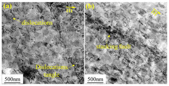
Figure 6.
TEM analysis of the FGH96 alloy after 70 h creep: (a) 0.34% pre-strained sample, (b) 1.05% pre-strained sample.
The influence of pre-strain on the creep rate depends on the creep mechanisms. The creep mechanism mainly included three types: dislocation gliding along the slip plane induced by thermal activation at a high stress level, dislocation movement induced by vacancy diffusion at a medium stress level, and diffusion creep controlled by atom diffusion at a low stress level. The creep mechanism was dependent on the testing temperature, stress, amount of pre-strain, and the resultant microstructure. According to existing experiments on FGH96 superalloys in the literature [1,2,3,4,20,21], slip-induced micro-twinning is the dominate deformation mechanism at 700 °C/690 MPa. An increase in pre-strain increases the dislocation density, thus resulting in a higher steady-state creep rate.
4.3. Validation of the Creep Rate Model
The parameters used in the model can be categorised as material constants, microstructure information, and fitted parameters. The material constants are listed in Table 1, including the magnitude of the Burgers vector (btp), the formation energy of two-layer PTs in secondary γ′ (Γpt), the formation energy of two-layer TTs in secondary γ′ (Γtt), the formation energy of two-layer TTs in the γ matrix (Γtm), the diffusion coefficient for reordering (Dord), and the diffusion length (x). Reordering involves the diffusion of Ni and Al atoms; a definite value of Dord was still unavailable. The diffusion coefficient of Al atoms in Ni3Al was obtained as [36]:
where R is the ideal gas constant (8.314 ) and T is the thermodynamic temperature.
The self-diffusion coefficient of Ni atoms in Ni3Al was obtained as [37]:
In the simulation, Dord was set as the average value of the two diffusion coefficients [25], i.e., . The diffusion length, x, was taken as twice the value of btp [25].
The volume fraction and diameter of the secondary γ′ were obtained from the experiments. As shown in Section 2, pre-strain within 6% did not have obvious effects on γ′ precipitations; therefore, the volume fraction and diameter of γ′ in the sample without pre-strain were adopted, which means that the volume fraction, , was 40%, and the average diameter, , was 162 nm. The parameter was obtained according to the volume fraction, expressed as . The Taylor factor, M, was 3.06; this is commonly adopted in FCC materials [30]. The values of , k1, and k2 were calibrated by experimental data; their values are listed in Table 2. These three parameters were determined as follows. According to Equation (11), was determined using the steady-state strain rates of the sample without pre-strain. Then, the values of k1 and k2 were calibrated according to Equation (13) using the steady-state strain rates of the pre-strained samples. Finally, Equation (14) was adopted to calculate the creep rates using the parameters shown in Table 1 and Table 2.

Table 2.
Fitted parameters.

Table 1.
Parameters of the material constants.
Table 1.
Parameters of the material constants.
| btp (Å) | Γpt (J/m2) | Γtt (J/m2) | Γtm (J/m2) | Dord at 973 K (m2/s) | x |
|---|---|---|---|---|---|
| 1.44 [38] | 0.7 [25] | 0.02 [25] | 0.03 [39] | 3.24 × 10⁻²⁰ | 2 btp [25] |
As shown in Figure 7, the predicted steady-state creep rates increased with the increase in pre-strains and finally reached saturation value, which was related to the evolution of dislocation densities because the creep rate was proportional to dislocation density. According to Equation (14), the saturation dislocation density can be obtained as ; it was equal to 1.75 × 10¹³ m−2. Pre-strains of 6% had no obvious influence on the morphology and distribution of γ′ precipitates and pre-strains mainly affected the density of a/6<112> dislocations; therefore, an exponential function of dislocation density was adopted to identify the pre-strain effect.
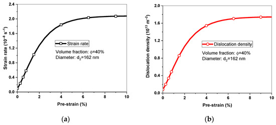
Figure 7.
Predicted (a) steady-state creep rates and (b) dislocation density under different pre-strains.
The comparisons between numerical calculated creep rates and experimental data are shown in Figure 8. The steady-state creep rates increased with the increase in pre-strain, and predicted data showed good agreement with experiment data, which indicated that the creep model proposed in this study could capture the pre-strain effect, considering the micro-twinning mechanism. The difference between the predicted results and the experimental data may result from the variations in microstructure, such as the volume fraction and the average diameter of γ′ precipitates. The pre-strain effects were included into the creep models by extrapolating the damage variable, internal stress, or strain rates from the literature [7,17,18,19]. Although creep resistance or creep enhancement effects induced by pre-strain could be captured in these models, they did not explicitly consider the creep mechanisms. In this study, the increase in dislocation density induced by pre-strain was reflected, and the steady-state creep rates were obtained by explicitly considering the slip-induced micro-twinning mechanism. The proposed model showed good applicability in micro-twinning-induced creep deformation, and provided an effective means for predicting the steady-state creep rates of materials with pre-strain.
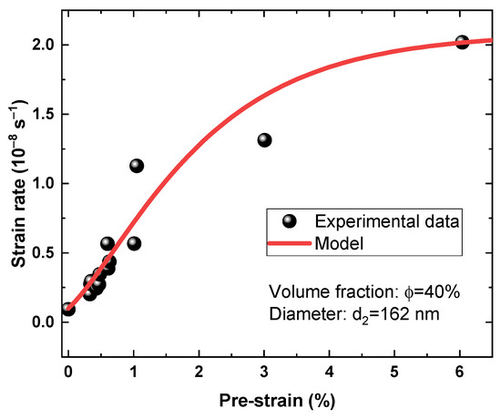
Figure 8.
Comparisons between the numerical steady-state creep rates and the experimental data.
5. Conclusions
Pre-tension experiments with various plastic strains at room temperature and subsequent creep tests at 700 °C/690 MPa were conducted for FGH96 alloys, and the microstructures after room-temperature pre-stain and high-temperature creep were analysed. Based on the micro-twinning mechanism, a steady-state creep rate model was established; the density of mobile dislocations evolved with pre-strain. The calculated steady-state creep rates were compared with the experimental data, and good agreement could be obtained. The main conclusions can be drawn as follows:
- (1)
- The steady-state creep rate and 70 h creep strain continuously increased with the increase in pre-strains. Compared with an unstrained specimen, the creep strain of pre-strained specimens accumulated rapidly in the first few hours, followed by a higher steady-state creep rate. For specimens with more than 1% pre-strain, the steady-state creep rate was more than 10 times greater than that of the unstrained specimen.
- (2)
- Room-temperature pre-tension within 6.04% plastic strain had no obvious influence on the morphology and distribution of γ′ precipitates, whereas the dislocation density continuously increased with the increase in pre-strains. The increases in mobile dislocation density after pre-strain were the main reasons for the increase in creep rates of FGH96 alloys.
- (3)
- The predicted steady-state creep rates showed good agreement with the experimental data; the creep model proposed in this study could capture the pre-strain effect while considering the micro-twinning mechanism.
Author Contributions
Conceptualization, H.W. and A.S.; Validation, J.Z. and H.D.; Investigation, J.Z. and Y.C.; Data curation, H.W., H.S. and Y.C.; Writing—original draft, H.W.; Supervision, H.D.; Project administration, A.S. All authors have read and agreed to the published version of the manuscript.
Funding
Financial support for this study was provided by the National Natural Science Foundation of China (Grant Numbers 11988102, 12102005, and 12202013).
Institutional Review Board Statement
Not applicable.
Informed Consent Statement
Not applicable.
Data Availability Statement
The data presented in this study are available on request from the corresponding author.
Conflicts of Interest
The authors declare that they have no known competing financial interest or personal relationship that could have appeared to influence the work reported in this paper.
References
- Peng, Z.; Zou, J.; Wang, Y.; Zhou, L.; Tang, Y. Effects of solution temperatures on creep resistance in a powder metallurgy nickel-based superalloy. Mater. Today Commun. 2021, 28, 102573. [Google Scholar] [CrossRef]
- Peng, Z.; Zou, J.; Yang, J.; Tian, G.; Wang, X. Influence of γ’ precipitate on deformation and fracture during creep in PM nickel-based superalloy. Prog. Nat. Sci. Mater. Int. 2021, 31, 303–309. [Google Scholar] [CrossRef]
- Peng, Z.; Zou, J.; Wang, X. Microstructural characterization of dislocation movement during creep in powder metallurgy FGH96 superalloy. Mater. Today Commun. 2020, 25, 101361. [Google Scholar] [CrossRef]
- Feng, Y.; Zhou, X.; Zou, J.; Tian, G. Effect of cooling rate during quenching on the microstructure and creep property of nickel-based superalloy FGH96. Int. J. Miner. Metall. Mater. 2019, 26, 493–499. [Google Scholar] [CrossRef]
- Shen, G.; Cooper, N.; Ottow, N.; Goetz, R.; Matlik, J. Integration and Automation of Residual Stress and Service Stress Modeling for Superalloy Component Design. In Superalloys 2012; Wiley: Hoboken, NJ, USA, 2012; pp. 129–134. [Google Scholar]
- Longuet, A.; Dumont, C.; Georges, E. Advanced modeling tools for processing and lifing of aeroengine components. In Superalloys 2020; Springer: Cham, Switzerland, 2020; pp. 3–15. [Google Scholar]
- Li, D.F.; O’Dowd, N.P.; Davies, C.M.; Nikbin, K.M. A review of the effect of prior inelastic deformation on high temperature mechanical response of engineering alloys. Int. J. Press. Vessel. Pip. 2010, 87, 531–542. [Google Scholar] [CrossRef]
- Chen, K.; Liu, C.; Ma, P.; Yang, J.; Zhan, L.; Huang, M.; Hu, J. Enhancing creep formability and comprehensive property in Al–Mg–Si alloy by combinatorial pre-ageing and large pre-deformation. Mater. Sci. Eng. A 2021, 826, 141967. [Google Scholar] [CrossRef]
- Král, P.; Dvořák, J.; Blum, W.; Sklenička, V.; Horita, Z.; Takizawa, Y.; Tang, Y.; Kunčická, L.; Kocich, R.; Kvapilova, M.; et al. The Effect of Predeformation on Creep Strength of 9% Cr Steel. Materials 2020, 13, 5330. [Google Scholar] [CrossRef]
- Marlin, R.T.; Cosandey, F.; Tien, J.K. The effect of predeformation on the creep and stress rupture of an oxide dispersion strengthened mechanical alloy. Metall. Trans. A 1980, 11, 1771–1775. [Google Scholar] [CrossRef]
- Cairney, J.M.; Rong, T.S.; Jones, I.P.; Smallman, R.E. Intermediate temperature creep mechanisms in Ni3Al. Philos. Mag. 2003, 83, 1827–1843. [Google Scholar] [CrossRef]
- Zhang, Y.H.; Knowles, D.M. Prestraining effect on creep behaviour of nickel base C263 superalloy. Mater. Sci. Technol. 2002, 18, 917–923. [Google Scholar] [CrossRef]
- Dyson, B.F.; Rodgers, M.J. Prestrain, Cavitation, and Creep Ductility. Met. Sci. 1974, 8, 261–266. [Google Scholar] [CrossRef]
- Dyson, B.F.; Loveday, M.S.; Rodgers, M.J. Grain boundary cavitation under various states of applied stress. Proc. R. Soc. Lond. A. Math. Phys. Sci. 1976, 349, 245–259. [Google Scholar]
- Loveday, M.S.; Dyson, B.F. Prestrain-induced particle microcracktng and creep cavitation in IN597. Acta Metall. 1983, 31, 397–405. [Google Scholar] [CrossRef]
- Peleshko, V.A. Applied creep theory for bodies with anisotropy due to plastic prestrain. Mech. Sol. 2007, 42, 307–320. [Google Scholar] [CrossRef]
- Endo, T.; Shi, J. Factors Affecting the Creep Rate and Creep Life of a 2. In 25 Cr-1 Mo Steel Under Constant Load. In Proceedings of the Strength of Materials, ICSMA 10, Sendai, Japan, 21–26 August 1994; pp. 665–668. [Google Scholar]
- Murakami, S.; Sanomura, Y.; Hattori, M. Modelling of the coupled effect of plastic damage and creep damage in Nimonic 80a. Int. J. Solids Struct. 1986, 22, 373–386. [Google Scholar] [CrossRef]
- Xia, Z.; Ellyin, F. A Rate-Dependent Inelastic Constitutive Model—Part II: Creep Deformation Including Prior Plastic Strain Effects. J. Eng. Mater. Technol. 1991, 113, 324–328. [Google Scholar] [CrossRef]
- Peng, Z.; Liu, P.; Wang, X.; Luo, X.; Liu, J.; Zou, J. Creep Behavior of FGH96 Superalloy at Different Service Conditions. Acta Metall. Sin. 2022, 58, 673–682. [Google Scholar]
- Li, M.; Pham, M.; Peng, Z.; Tian, G.; Shollock, B.A. Creep deformation mechanisms and CPFE modelling of a nickel-base superalloy. Mater. Sci.Eng. A 2018, 718, 147–156. [Google Scholar] [CrossRef]
- Kolbe, M. The high temperature decrease of the critical resolved shear stress in nickel-base superalloys. Mater. Sci. Eng. A 2001, 319–321, 383–387. [Google Scholar] [CrossRef]
- Brinckmann, S.; Siegmund, T.; Huang, Y. A dislocation density based strain gradient model. Int. J. Plast. 2006, 22, 1784–1797. [Google Scholar] [CrossRef]
- Kovarik, L.; Unocic, R.R.; Li, J.; Sarosi, P.M.; Chen, S.; Wang, Y.; Mills, M.J. Microtwinning and other shearing mechanisms at intermediate temperatures in Ni-based superalloys. Prog. Mater. Sci. 2009, 54, 839–873. [Google Scholar] [CrossRef]
- Karthikeyan, S.; Unocic, R.R.; Sarosi, P.M.; Viswanathan, G.B.; Whitis, D.D.; Mills, M.J. Modeling microtwinning during creep in Ni-based superalloys. Scr. Mater. 2006, 54, 1157–1162. [Google Scholar] [CrossRef]
- Mittemeijer, E.J. Fundamentals of Materials Science; Springer: New York, NY, USA, 2010. [Google Scholar]
- Proudhon, H.; Poole, W.J.; Wang, X.; Bréchet, Y. The role of internal stresses on the plastic deformation of the Al–Mg–Si–Cu alloy AA6111. Philos. Mag. 2008, 88, 621–640. [Google Scholar] [CrossRef]
- Liu, Y.; Liu, W.; Yu, L.; Sui, H.; Cheng, Y.; Duan, H. Size-dependent to size-independent transition in creep of single crystalline Cu micropillars. Extreme Mech. Lett. 2022, 56, 101843. [Google Scholar] [CrossRef]
- Taylor, G.I. Plastic strain in metals. J. Inst. Met. 1938, 62, 307–324. [Google Scholar]
- Stoller, R.E.; Zinkle, S.J. On the relationship between uniaxial yield strength and resolved shear stress in polycrystalline materials. J. Nucl. Mater. 2000, 283–287, 349–352. [Google Scholar] [CrossRef]
- Kocks, U.F.; Mecking, H. Physics and phenomenology of strain hardening: The FCC case. Prog. Mater. Sci. 2003, 48, 171–273. [Google Scholar] [CrossRef]
- Mecking, H.; Kocks, U.F. Kinetics of flow and strain-hardening. Acta Metall. 1981, 29, 1865–1875. [Google Scholar] [CrossRef]
- Sinclair, C.W.; Poole, W.J.; Bréchet, Y. A model for the grain size dependent work hardening of copper. Scr. Mater. 2006, 55, 739–742. [Google Scholar] [CrossRef]
- Yu, L.; Xiao, X.; Chen, L.; Cheng, Y.; Duan, H. A hierarchical theoretical model for mechanical properties of lath martensitic steels. Int. J. Plast. 2018, 111, 135–151. [Google Scholar] [CrossRef]
- Fan, X.; Guo, Z.; Wang, X.; Yang, J.; Zou, J. Morphology evolution of γ′ precipitates in a powder metallurgy Ni-base superalloy. Mater. Charact. 2018, 139, 382–389. [Google Scholar] [CrossRef]
- Cserháti, C.; Paul, A.; Kodentsov, A.A.; van Dal, M.J.H.; van Loo, E.J.J. Intrinsic diffusion in Ni3Al system. Intermetallics 2003, 11, 291–297. [Google Scholar] [CrossRef]
- Frank, S.; Södervall, U.; Herzig, C. Self-Diffusion of Ni in Single and Polycrystals of Ni3Al. A Study of SIMS and Radiotracer Analysis. Phys. Status Solidi B 1995, 191, 45–55. [Google Scholar] [CrossRef]
- Kibey, S.; Liu, J.B.; Johnson, D.D.; Sehitoglu, H. Predicting twinning stress in fcc metals: Linking twin-energy pathways to twin nucleation. Acta Mater. 2007, 55, 6843–6851. [Google Scholar] [CrossRef]
- Yuan, Y.; Gu, Y.F.; Cui, C.Y.; Osada, T.; Tetsui, T.; Yokokawa, T.; Harada, H. Creep mechanisms of U720Li disc superalloy at intermediate temperature. Mater. Sci. Eng. A 2011, 528, 5106–5111. [Google Scholar] [CrossRef]
Disclaimer/Publisher’s Note: The statements, opinions and data contained in all publications are solely those of the individual author(s) and contributor(s) and not of MDPI and/or the editor(s). MDPI and/or the editor(s) disclaim responsibility for any injury to people or property resulting from any ideas, methods, instructions or products referred to in the content. |
© 2023 by the authors. Licensee MDPI, Basel, Switzerland. This article is an open access article distributed under the terms and conditions of the Creative Commons Attribution (CC BY) license (https://creativecommons.org/licenses/by/4.0/).