
Pulse Burst Generation and Diffraction with Spatial Light Modulators for Dynamic Ultrafast Laser Materials Processing
 , ,
, , 
 and
and 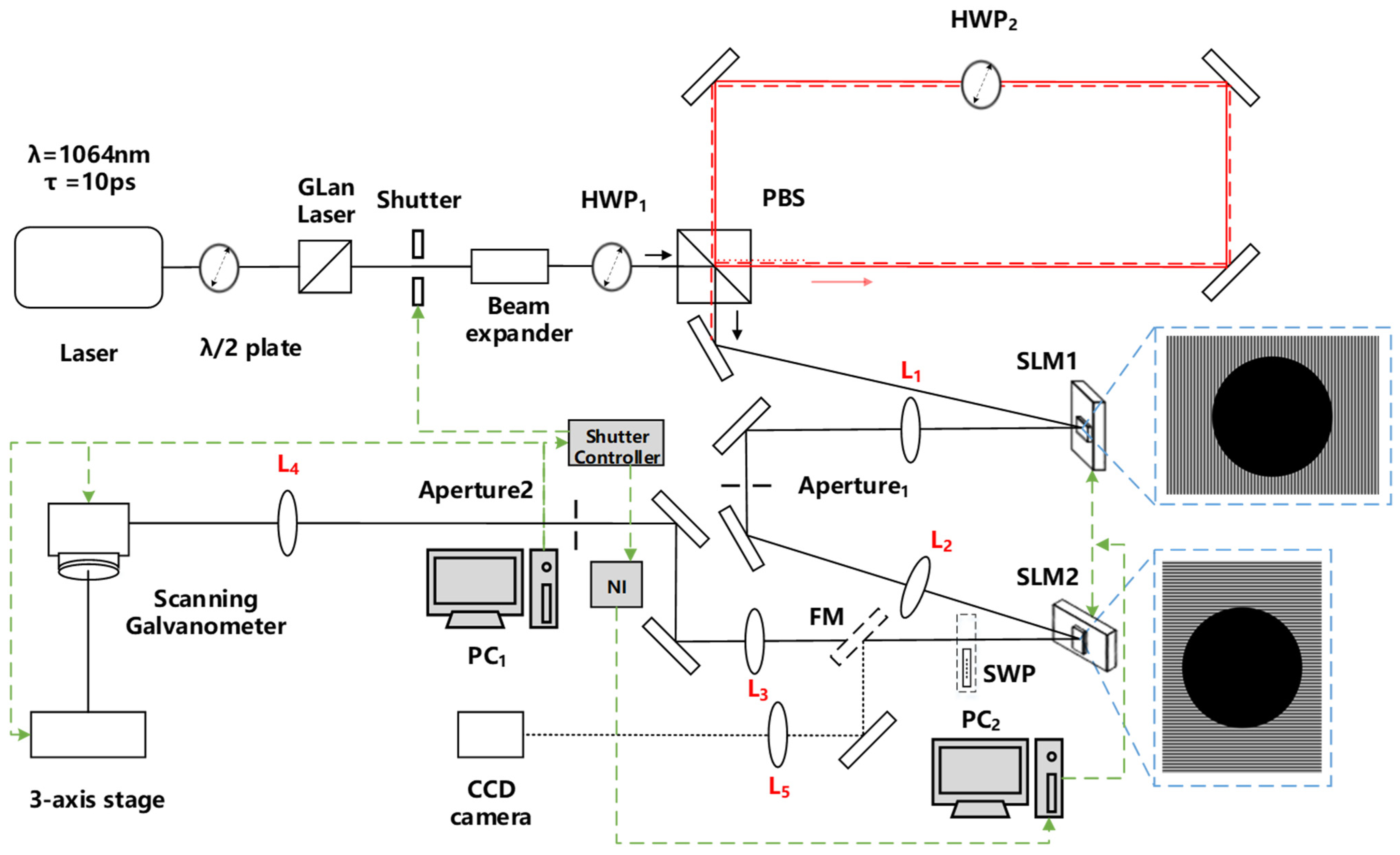
Abstract
1. Introduction
2. Materials and Methods
2.1. Optical Setup
2.2. Pulse Burst Generator
3. Results
3.1. Hybrid CGHs
3.2. Fast Photo-Diode Outputs
3.3. Ultrafast Ablation with Orthogonal Linear Polarisations
3.4. Pulse Burst Ablation with Orthogonal Radial and Azimuthal Polarisations
3.5. Scanning with Orthogonal Linear Polarisations, Fixed CGHs Polarisations
3.6. Dynamic Polarisation Modulation and Micro-Structuring
3.7. Comparison of Burst Mode with Single Pulse Processing
4. Discussion
5. Conclusions
Author Contributions
Funding
Institutional Review Board Statement
Informed Consent Statement
Data Availability Statement
Acknowledgments
Conflicts of Interest
References
- Maiuri, M.; Garavelli, M.; Cerullo, G. Ultrafast Spectroscopy: State of the Art and Open Challenges. J. Am. Chem. Soc. 2020, 142, 3–15. [Google Scholar] [CrossRef] [PubMed]
- Öktem, B.; Pavlov, I.; Ilday, S.; Kalaycioğlu, H.; Rybak, A.; Yavaş, S.; Erdoğan, M.; Ilday, F.Ö. Nonlinear Laser Lithography for Indefinitely Large-Area Nanostructuring with Femtosecond Pulses. Nat. Photonics 2013, 7, 897–901. [Google Scholar] [CrossRef]
- Huber, H.P.; Stroj, S.; Vorarlberg, F.; Huber, H.P.; Herrnberger, F.; Kery, S.; Zoppel, S. Selective Structuring of Thin-Film Solar Cells by Ultrafast Laser Ablation; SPIE Digital Library: Bellingham, WA, USA, 2008. [Google Scholar] [CrossRef]
- Fernandes, S.A.; Schöps, B.; Nett, R.; Dobbelstein, H.; Stümmler, D.; Ostendorf, A. Laser Ablation of a Thin Film Multilayer for Organic Solar Cells; ResearchGate: Berlin, Germany, 2013. [Google Scholar] [CrossRef]
- Giannuzzi, G.; Gaudiuso, C.; di Mundo, R.; Mirenghi, L.; Fraggelakis, F.; Kling, R.; Lugarà, P.M.; Ancona, A. Short and Long Term Surface Chemistry and Wetting Behaviour of Stainless Steel with 1D and 2D Periodic Structures Induced by Bursts of Femtosecond Laser Pulses. Appl. Surf. Sci. 2019, 494, 1055–1065. [Google Scholar] [CrossRef]
- Jalil, S.A.; Akram, M.; Bhat, J.A.; Hayes, J.J.; Singh, S.C.; ElKabbash, M.; Guo, C. Creating Superhydrophobic and Antibacterial Surfaces on Gold by Femtosecond Laser Pulses. Appl. Surf. Sci. 2020, 506, 144952. [Google Scholar] [CrossRef]
- Anoop, K.K.; Rubano, A.; Fittipaldi, R.; Wang, X.; Paparo, D.; Vecchione, A.; Marrucci, L.; Bruzzese, R.; Amoruso, S. Femtosecond Laser Surface Structuring of Silicon Using Optical Vortex Beams Generated by a Q-Plate. Appl. Phys. Lett. 2014, 104, 241604. [Google Scholar] [CrossRef]
- Ouyang, J.; Perrie, W.; Allegre, O.J.; Heil, T.; Jin, Y.; Fearon, E.; Eckford, D.; Edwardson, S.P.; Dearden, G. Tailored Optical Vector Fields for Ultrashort-Pulse Laser Induced Complex Surface Plasmon Structuring. Opt. Express 2015, 23, 12562–12572. [Google Scholar] [CrossRef]
- Schille, J.; Loeschner, U. Ultrashort Pulse Lasers in High-Rate Laser Micro Processing—Quo Vadis? Adv. Opt. Technol. 2021, 10, 233–237. [Google Scholar] [CrossRef]
- Liu, Y.; Wu, J.; Wen, X.; Lin, W.; Wang, W.; Guan, X.; Qiao, T.; Guo, Y.; Wang, W.; Wei, X.; et al. >100 W GHz Femtosecond Burst Mode All-Fiber Laser System at 10 Μm. Opt. Express 2020, 28, 13414–13422. [Google Scholar] [CrossRef]
- Nubbemeyer, T.; Kaumanns, M.; Ueffing, M.; Gorjan, M.; Alismail, A.; Fattahi, H.; Brons, J.; Pronin, O.; Barros, H.G.; Major, Z.; et al. 1 KW, 200 MJ Picosecond Thin-Disk Laser System. Opt. Lett. 2017, 42, 1381–1384. [Google Scholar] [CrossRef]
- Förster, D.J.; Jäggi, B.; Michalowski, A.; Neuenschwander, B. Review on Experimental and Theoretical Investigations of Ultra-Short Pulsed Laser Ablation of Metals with Burst Pulses. Materials 2021, 14, 3331. [Google Scholar] [CrossRef]
- Kerse, C.; Kalaycloĝlu, H.; Elahi, P.; Çetin, B.; Kesim, D.K.; Akçaalan, Ö.; Yavaş, S.; Aşlk, M.D.; Öktem, B.; Hoogland, H.; et al. Ablation-Cooled Material Removal with Ultrafast Bursts of Pulses. Nature 2016, 537, 84–88. [Google Scholar] [CrossRef]
- Žemaitis, A.; Gečys, P.; Barkauskas, M.; Račiukaitis, G.; Gedvilas, M. Highly-Efficient Laser Ablation of Copper by Bursts of Ultrashort Tuneable (Fs-Ps) Pulses. Sci. Rep. 2019, 9, 12280. [Google Scholar] [CrossRef] [PubMed]
- Mur, J.; Petkovšek, R. Near-THz Bursts of Pulses—Governing Surface Ablation Mechanisms for Laser Material Processing. Appl. Surf. Sci. 2019, 478, 355–360. [Google Scholar] [CrossRef]
- Domke, M.; Matylitsky, V.; Stroj, S. Surface Ablation Efficiency and Quality of Fs Lasers in Single-Pulse Mode, Fs Lasers in Burst Mode, and Ns Lasers. Appl. Surf. Sci. 2020, 505, 144594. [Google Scholar] [CrossRef]
- Obata, K.; Caballero-Lucas, F.; Sugioka, K. Material Processing at GHz Burst Mode by Femtosecond Laser Ablation. J. Laser Micro Nanoeng. 2021, 16, 19–23. [Google Scholar] [CrossRef]
- Salter, P.S.; Booth, M.J. Adaptive Optics in Laser Processing. Light Sci. Appl. 2019, 8, 110. [Google Scholar] [CrossRef]
- Silvennoinen, M.; Kaakkunen, J.; Paivasaari, K.; Vahimaa, P. Parallel Microstructuring Using Femtosecond Laser and Spatial Light Modulator. Phys. Procedia 2013, 41, 693–697. [Google Scholar] [CrossRef]
- Kautek, W.; Krueger, J. Femtosecond pulse laser ablation of metallic, semiconducting, ceramic, and biological materials. In Laser Materials Processing: Industrial and Microelectronics Applications; SPIE Digital Library: Bellingham, WA, USA, 1994; Volume 2207, pp. 600–611. [Google Scholar] [CrossRef]
- Ihlemann, J.; Wolff, B.; Simon, P. Nanosecond and Femtosecond Excimer Laser Ablation of Fused Silica. Appl. Phys. A Solids Surf. 1992, 54, 363–368. [Google Scholar] [CrossRef]
- Hasegawa, S.; Hayasaki, Y. Polarization Distribution Control of Parallel Femtosecond Pulses with Spatial Light Modulators. Opt. Express 2013, 21, 12987–12995. [Google Scholar] [CrossRef]
- Mikhaylov, D. Ultrashort Pulse Laser Ablation of Bulk Materials Using Shaped Laser Beams. Ph.D. Thesis, University of Dresden, Dresden, Germany, Cuvillier-Verlag, Gottingen, Germany, 2021. [Google Scholar]
- Lou, K.; Qian, S.X.; Ren, Z.C.; Tu, C.; Li, Y.; Wang, H.T. Femtosecond Laser Processing by Using Patterned Vector Optical Fields. Sci. Rep. 2013, 3, 2281. [Google Scholar] [CrossRef]
- Rosales-Guzmán, C.; Bhebhe, N.; Forbes, A. Generation of Multiple Vector Beams from a Single Digital Hologram. arXiv 2017, arXiv:1708.02485v1[physics.optics]. [Google Scholar]
- Zhu, G.; Whitehead, D.; Perrie, W.; Allegre, O.J.; Olle, V.; Li, Q.; Tang, Y.; Dawson, K.; Jin, Y.; Edwardson, S.P.; et al. Investigation of the Thermal and Optical Performance of a Spatial Light Modulator with High Average Power Picosecond Laser Exposure for Materials Processing Applications. J. Phys. D Appl. Phys. 2018, 51, 095603. [Google Scholar] [CrossRef]
- Liu, D.; Wang, Y.; Zhai, Z.; Fang, Z.; Tao, Q.; Perrie, W.; Edwarson, S.P.; Dearden, G. Dynamic Laser Beam Shaping for Material Processing Using Hybrid Holograms. Opt. Laser Technol. 2018, 102, 68–73. [Google Scholar] [CrossRef]
- Shimotsuma, Y.; Kazansky, P.G.; Qiu, J.; Hirao, K. Self-Organized Nanogratings in Glass Irradiated by Ultrashort Light Pulses. Phys. Rev. Lett. 2003, 91, 247405. [Google Scholar] [CrossRef] [PubMed]
- Beresna, M.; Gecevičius, M.; Kazansky, P.G.; Gertus, T. Radially Polarized Optical Vortex Converter Created by Femtosecond Laser Nanostructuring of Glass. Appl. Phys. Lett. 2011, 98, 201101. [Google Scholar] [CrossRef]
- Zhang, F.; Yamaguchi, I.; Yaroslavsky, L.P. Algorithm for Reconstruction of Digital Holograms with Adjustable Magnification. Opt. Lett. 2004, 29, 1668–1670. [Google Scholar] [CrossRef]
- Milione, G.; Sztul, H.I.; Nolan, D.A.; Alfano, R.R. Higher-Order Poincaré Sphere, Stokes Parameters, and the Angular Momentum of Light. Phys. Rev. Lett. 2011, 107, 053601. [Google Scholar] [CrossRef]
- Machavariani, G.; Lumer, Y.; Moshe, I.; Jackel, S. Effect of the Spiral Phase Element on the Radial-Polarization (0, 1)* LG Beam. Opt. Commun. 2007, 271, 190–196. [Google Scholar] [CrossRef]
- Fraggelakis, F.; Mincuzzi, G.; Manek-Hönninger, I.; Lopez, J.; Kling, R. Generation of Micro- and Nano-Morphologies on a Stainless Steel Surface Irradiated with 257 Nm Femtosecond Laser Pulses. RSC Adv. 2018, 8, 16082–16087. [Google Scholar] [CrossRef]
- Bonse, J. Quo Vadis LIPSS?—Recent and Future Trends on Laser-Induced Periodic Surface Structures. Nanomaterials 2020, 10, 1950. [Google Scholar] [CrossRef]
- Wen, S.B.; Mao, X.; Greif, R.; Russo, R.E. Expansion of the Laser Ablation Vapor Plume into a Background Gas. I. Analysis. J. Appl. Phys. 2007, 101, 023114. [Google Scholar] [CrossRef]
- König, J.; Nolte, S.; Tünnermann, A. Plasma Evolution during Metal Ablation with Ultrashort Laser Pulses. Opt. Express 2005, 13, 10597–10607. [Google Scholar] [CrossRef] [PubMed]
- Farid, N.; Harilal, S.S.; Ding, H.; Hassanein, A. Dynamics of Ultrafast Laser Plasma Expansion in the Presence of an Ambient. Appl. Phys. Lett. 2013, 103, 191112. [Google Scholar] [CrossRef]
- Metzner, D.; Lickschat, P.; Weißmantel, S. Influence of Heat Accumulation during Laser Micromachining of CoCrMo Alloy with Ultrashort Pulses in Burst Mode. Appl. Phys. A Mater. Sci. Process. 2020, 126, 84. [Google Scholar] [CrossRef]
- Förster, D.J.; Faas, S.; Gröninger, S.; Bauer, F.; Michalowski, A.; Weber, R.; Graf, T. Shielding Effects and Re-Deposition of Material during Processing of Metals with Bursts of Ultra-Short Laser Pulses. Appl. Surf. Sci. 2018, 440, 926–931. [Google Scholar] [CrossRef]
- Pereira, A.; Delaporte, P.; Sentis, M.; Cros, A.; Marine, W.; Basillais, A.; Thomann, A.L.; Leborgne, C.; Semmar, N.; Andreazza, P.; et al. Laser Treatment of a Steel Surface in Ambient Air. Thin Solid Film. 2004, 453–454, 16–21. [Google Scholar] [CrossRef]
- Ndagano, B.; Nape, I.; Cox, M.A.; Rosales-Guzman, C.; Forbes, A. Creation and Detection of Vector Vortex Modes for Classical and Quantum Communication. J. Lightwave Technol. 2018, 36, 292–301. [Google Scholar] [CrossRef]
- Tang, Y.; Perrie, W.; Schille, J.; Loeschner, U.; Li, Q.; Liu, D.; Edwardson, S.P.; Forbes, A.; Dearden, G. High-Quality Vector Vortex Arrays by Holographic and Geometric Phase Control. J. Phys. D Appl. Phys. 2020, 53, 465101. [Google Scholar] [CrossRef]
- Balachninaitė, O.; Tamulienė, V.; Eičas, L.; Vaičaitis, V. Laser Micromachining of Steel and Copper Using Femtosecond Laser Pulses in GHz Burst Mode. Results Phys. 2021, 22, 103847. [Google Scholar] [CrossRef]
- Fraggelakis, F.; Mincuzzi, G.; Lopez, J.; Manek-Hönninger, I.; Kling, R. Controlling 2D Laser Nano Structuring over Large Area with Double Femtosecond Pulses. Appl. Surf. Sci. 2019, 470, 677–686. [Google Scholar] [CrossRef]
- Jin, Y.; Allegre, O.J.; Perrie, W.; Abrams, K.; Ouyang, J.; Fearon, E.; Edwardson, S.P.; Dearden, G. Dynamic Modulation of Spatially Structured Polarization Fields for Real-Time Control of Ultrafast Laser-Material Interactions. Opt. Express 2013, 21, 25333–25343. [Google Scholar] [CrossRef] [PubMed]


Publisher’s Note: MDPI stays neutral with regard to jurisdictional claims in published maps and institutional affiliations. |
© 2022 by the authors. Licensee MDPI, Basel, Switzerland. This article is an open access article distributed under the terms and conditions of the Creative Commons Attribution (CC BY) license (https://creativecommons.org/licenses/by/4.0/).
Share and Cite
Fang, Z.; Zhou, T.; Perrie, W.; Bilton, M.; Schille, J.; Löschner, U.; Edwardson, S.; Dearden, G. Pulse Burst Generation and Diffraction with Spatial Light Modulators for Dynamic Ultrafast Laser Materials Processing. Materials 2022, 15, 9059. https://doi.org/10.3390/ma15249059
Fang Z, Zhou T, Perrie W, Bilton M, Schille J, Löschner U, Edwardson S, Dearden G. Pulse Burst Generation and Diffraction with Spatial Light Modulators for Dynamic Ultrafast Laser Materials Processing. Materials. 2022; 15(24):9059. https://doi.org/10.3390/ma15249059
Chicago/Turabian StyleFang, Zheng, Tong Zhou, Walter Perrie, Matthew Bilton, Jörg Schille, Udo Löschner, Stuart Edwardson, and Geoff Dearden. 2022. "Pulse Burst Generation and Diffraction with Spatial Light Modulators for Dynamic Ultrafast Laser Materials Processing" Materials 15, no. 24: 9059. https://doi.org/10.3390/ma15249059
APA StyleFang, Z., Zhou, T., Perrie, W., Bilton, M., Schille, J., Löschner, U., Edwardson, S., & Dearden, G. (2022). Pulse Burst Generation and Diffraction with Spatial Light Modulators for Dynamic Ultrafast Laser Materials Processing. Materials, 15(24), 9059. https://doi.org/10.3390/ma15249059