

Numerical–Experimental Analysis toward the Strain Rate Sensitivity of 3D-Printed Nylon Reinforced by Short Carbon Fiber

 ,
,  ,
,  , and
, and 
Abstract
1. Introduction
2. Materials and Methods
2.1. Material
2.2. 3D Printer Device
2.3. Characterization Methods and Experimental Procedure
2.3.1. Microscopic Observation
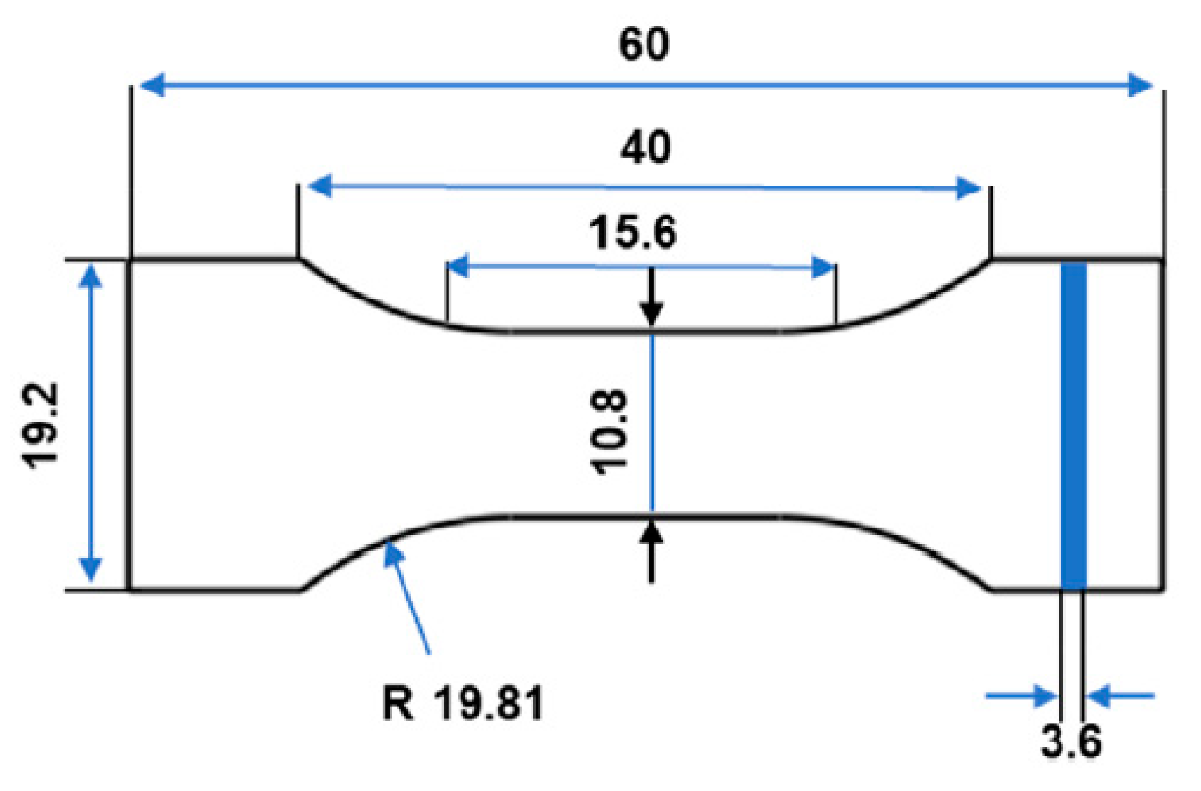
2.3.2. Mechanical Testing (Quasi-Static Tensile Test)
2.4. Condition of Printing
3. Results and Discussions
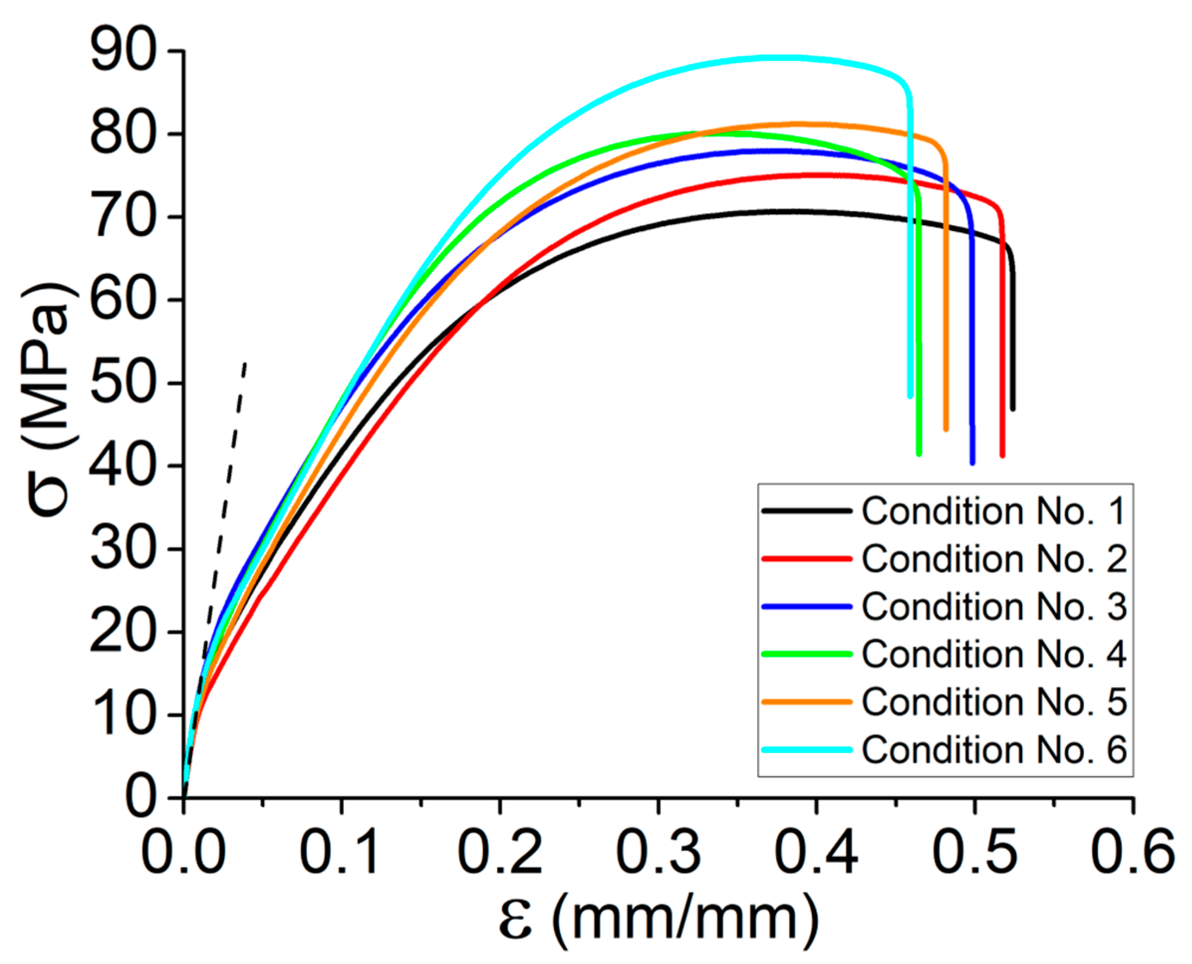
3.1. Individual Effect of Process Parameters on Mechanical Properties of 3D-Printed Onyx
- By increasing the platform temperature from 70 °C to 110 °C in the same print speed, Young’s modulus and tensile strength increased by 10% and 11%, respectively.
- By increasing the print speed in the range of 40 mm·s−1 to 60 mm·s−1 (e.g., conditions No. 1 and No. 4), the tensile strength of the Onyx increased by 14%.
- By increasing the platform temperature from 70 °C to 110 °C for the same print speed (e.g., conditions No.1 and No. 3), the failure strain decreased by 8%.
- By increasing the print speed in the range of 40 mm·s−1 to 60 mm·s−1 (e.g., conditions No. 3 and No. 6), the failure strain decreased by 11%.
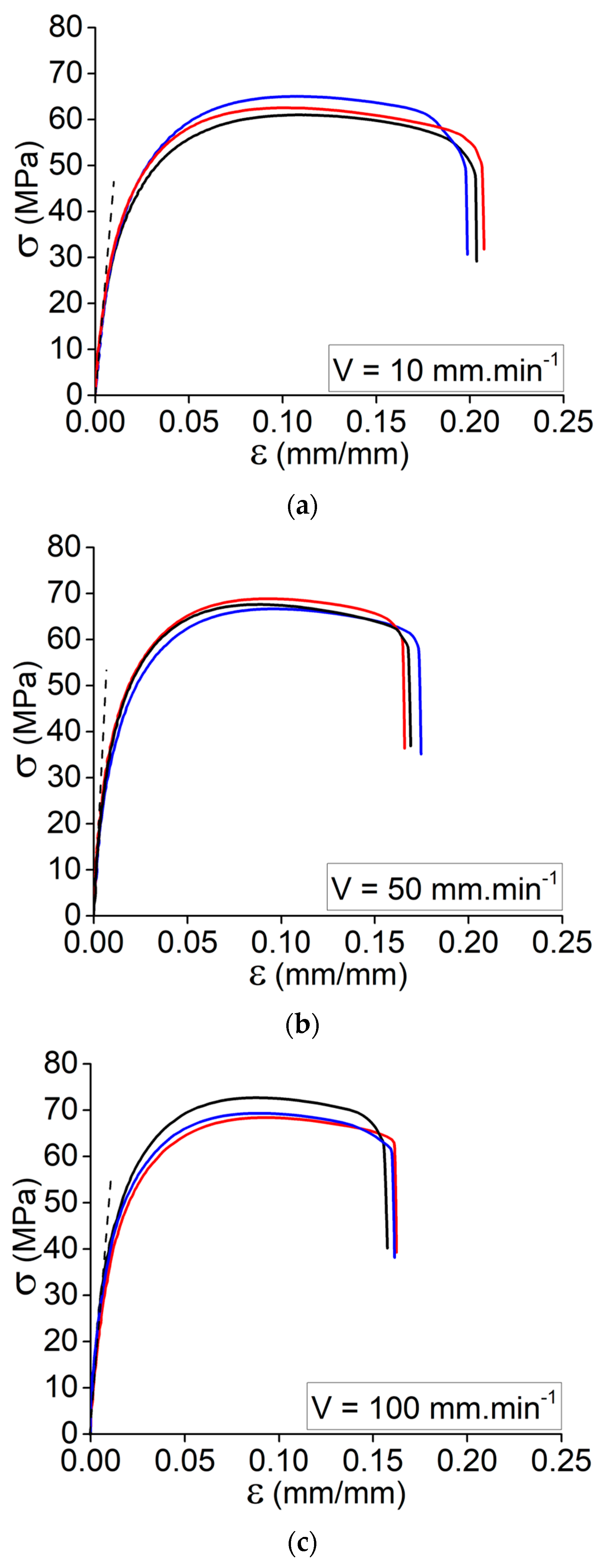
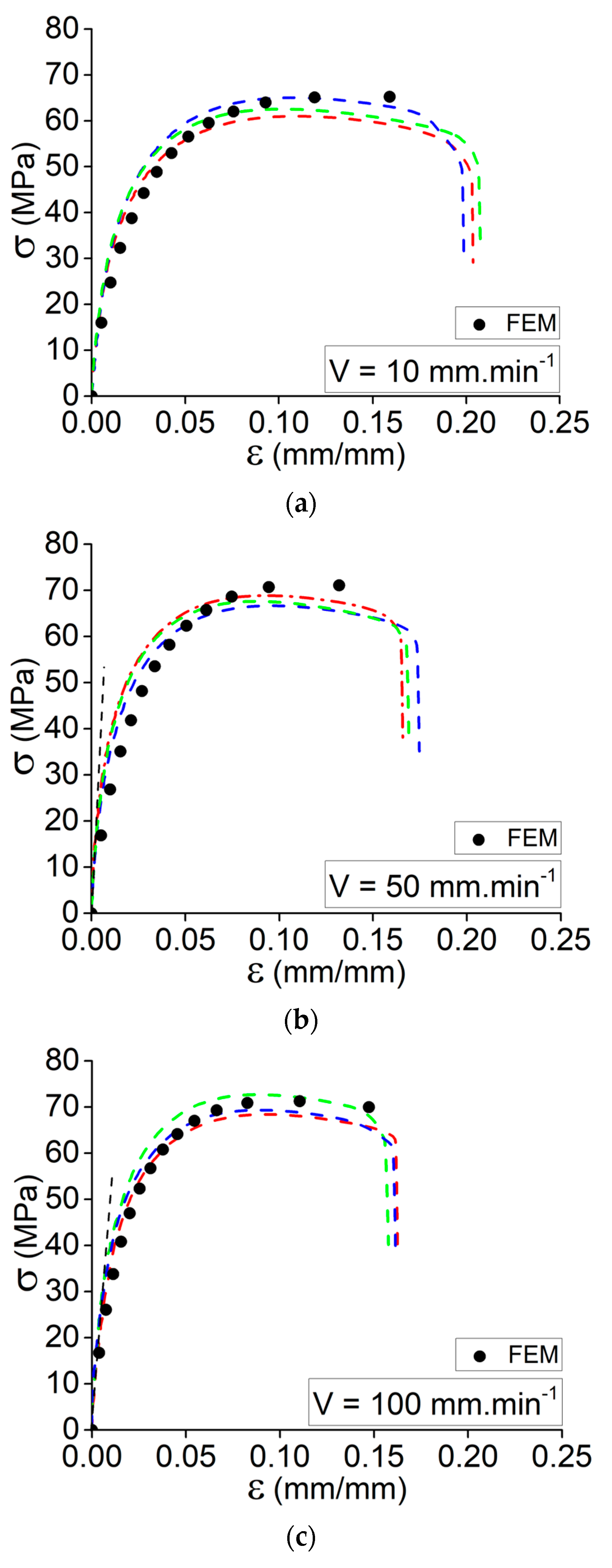
3.2. Tensile Properties as a Function of Strain Rate
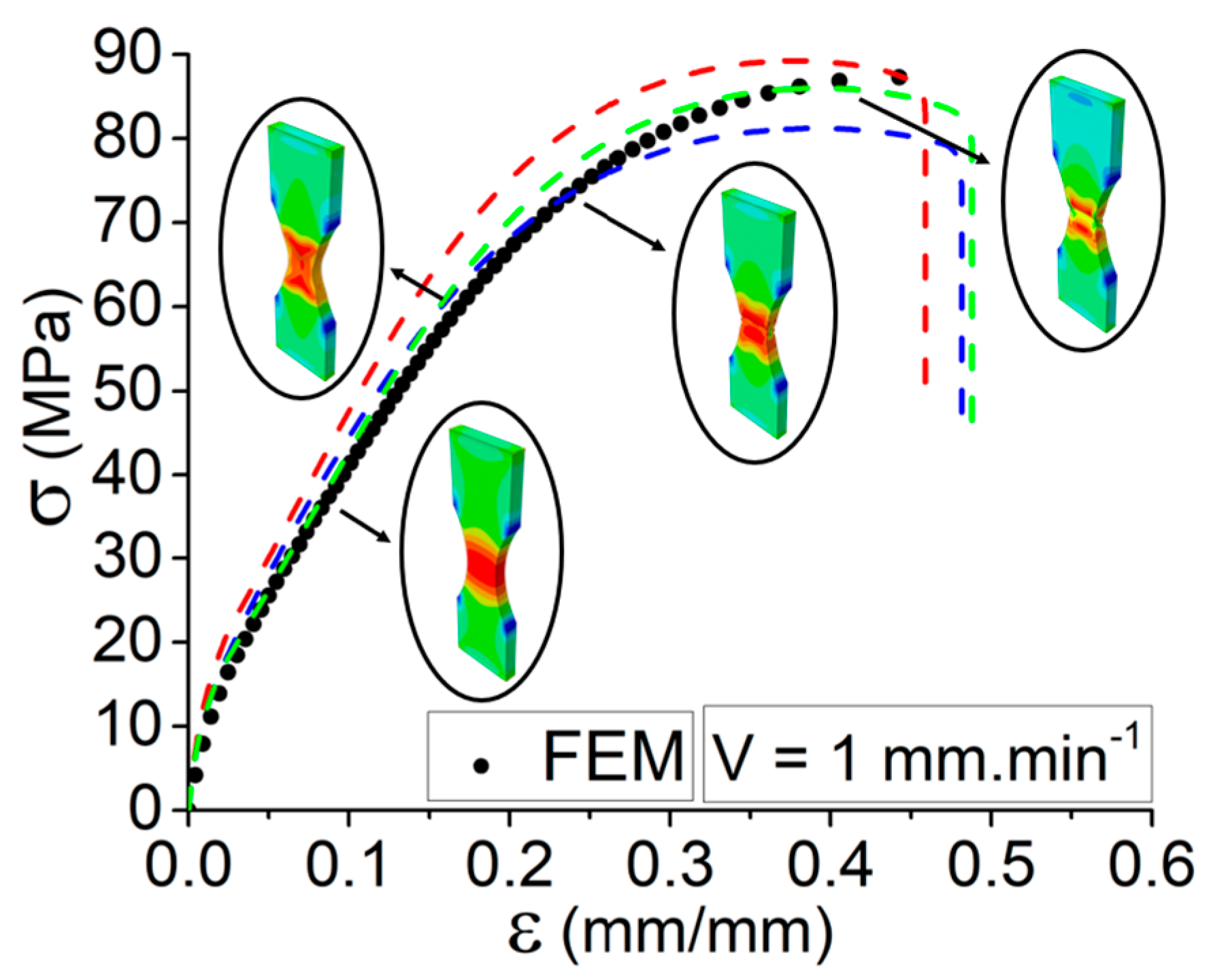
- By increasing the elongation speed from 1 mm·min−1 to 100 mm·min−1, there is a considerable increase in Young’s modulus.
- By increasing the elongation speed from 1 mm·min−1 to 10 mm·min−1, the ultimate stress decreases and then increases by increasing the elongation speed to 100 mm·min−1.
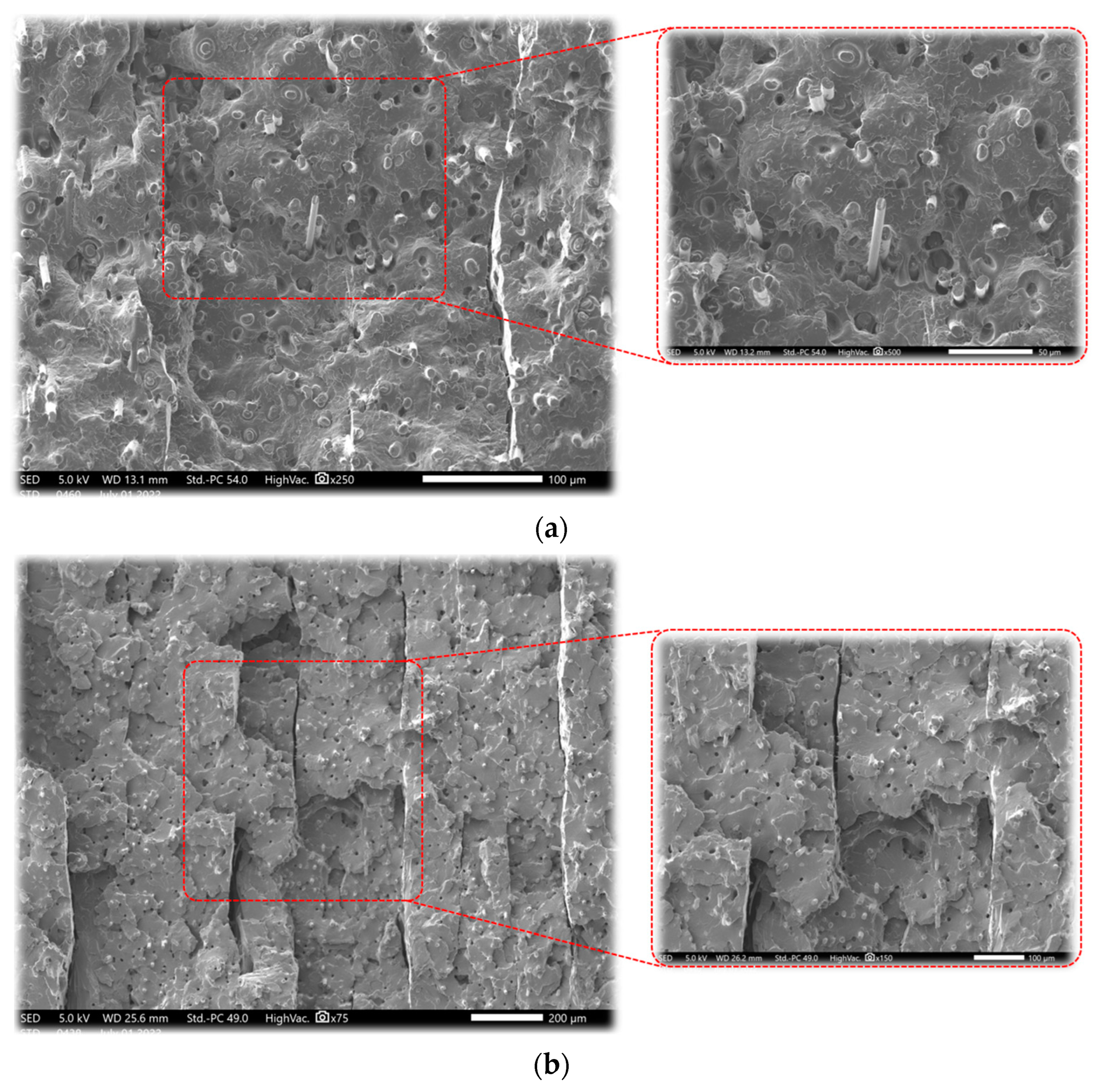
- The sudden reduction in the ultimate strength might be related to the variation of the failure mechanism from ductile failure to brittle failure (rapid matrix failure).
- By increasing the elongation speed from 10 mm·min−1 to 100 mm·min−1, the ultimate stress increases. It is still lower than the first elongation speed (failure mechanism: ductile to brittle failure).
- By increasing the elongation speed from 1 mm·min−1 to 10 mm·min−1, the strain of ultimate stress decreases, whereas it increases by further enhancement of the elongation speed.
3.3. Simulation Validation
4. Conclusions
- A strong variation of tensile behavior for each set of conditions has been observed during the quasi-static tensile test.
- The variation of 40 °C in the platform temperature results in a 10% and 11% increase in Young’s modulus and tensile strength and an 8% decrease in the failure strain, respectively.
- The variation of 20 mm·s−1 in print speed results in a 14% increase in the tensile strength and an 11% decrease in the failure strain.
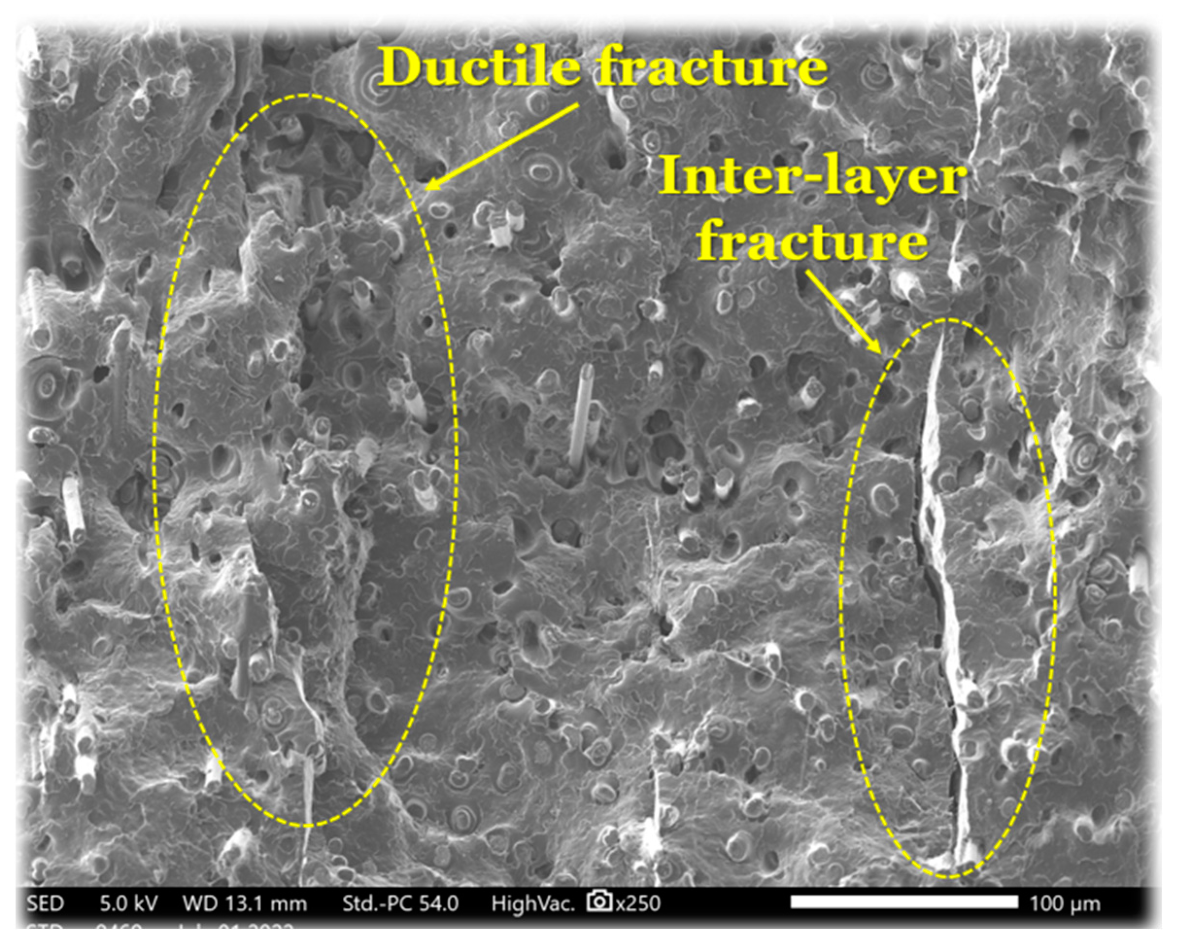
- The individual effect of process variables is inevitable and affects the mechanical behavior of the 3D-printed composite, as observed from the SEM micrographs (ductile to brittle fracture).
- Increase in the elongation speed from 1 mm·min−1 to 100 mm·min−1, results in a considerable increase inYoung’s modulus.
- The sudden reduction in the ultimate strength might be related to the variation of the failure mechanism from ductile failure to brittle failure (rapid matrix failure).
- SEM micrographs demonstrated that although the mechanical behavior of the material varied by increasing the strain rate, the failure mechanism altered from ductile to brittle failure.
Author Contributions
Funding
Institutional Review Board Statement
Informed Consent Statement
Data Availability Statement
Acknowledgments
Conflicts of Interest
References
- Gao, W.; Zhang, Y.; Ramanujan, D.; Ramani, K.; Chen, Y.; Williams, C.B.; Wang, C.C.L.; Shin, Y.C.; Zhang, S.; Zavattieri, P.D. The status, challenges, and future of additive manufacturing in engineering. Comput.-Aided Des. 2015, 69, 65–89. [Google Scholar] [CrossRef]
- El Magri, A.; Vaudreuil, S.; El Mabrouk, K.; Touhami, M.E. Printing temperature effects on the structural and mechanical performances of 3D printed Poly-(phenylene sulfide) material. IOP Conf. Ser. Mater. Sci. Eng. 2020, 783, 012001. [Google Scholar] [CrossRef]
- EL Magri, A.; El Mabrouk, K.; Vaudreuil, S.; Chibane, H.; Touhami, M.E. Optimization of printing parameters for improvement of mechanical and thermal performances of 3D printed poly(ether ether ketone) parts. J. Appl. Polym. Sci. 2020, 137, 49087. [Google Scholar] [CrossRef]
- El Magri, A.; Bencaid, S.E.; Vanaei, H.R.; Vaudreuil, S. Effects of Laser Power and Hatch Orientation on Final Properties of PA12 Parts Produced by Selective Laser Sintering. Polymers 2022, 14, 3674. [Google Scholar] [CrossRef] [PubMed]
- Anderson, I. Mechanical Properties of Specimens 3D Printed with Virgin and Recycled Polylactic Acid. 3D Print. Addit. Manuf. 2017, 4, 110–115. [Google Scholar] [CrossRef]
- Galeja, M.; Hejna, A.; Kosmela, P.; Kulawik, A. Static and Dynamic Mechanical Properties of 3D Printed ABS as a Function of Raster Angle. Materials 2020, 13, 297. [Google Scholar] [CrossRef] [PubMed]
- EL Magri, A.; El Mabrouk, K.; Vaudreuil, S.; Touhami, M.E. Mechanical properties of CF-reinforced PLA parts manufactured by fused deposition modeling. J. Thermoplast. Compos. Mater. 2021, 34, 581–595. [Google Scholar] [CrossRef]
- Vanaei, H.R.; Raissi, K.; Deligant, M.; Shirinbayan, M.; Fitoussi, J.; Khelladi, S.; Tcharkhtchi, A. Toward the understanding of temperature effect on bonding strength, dimensions and geometry of 3D-printed parts. J. Mater. Sci. 2020, 55, 14677–14689. [Google Scholar] [CrossRef]
- Masood, S.H.; Mau, K.; Song, W. Tensile Properties of Processed FDM Polycarbonate Material. Mater. Sci. Forum 2010, 654–656, 2556–2559. [Google Scholar] [CrossRef]
- Dul, S.; Fambri, L.; Pegoretti, A. Fused deposition modelling with ABS–graphene nanocomposites. Compos. Part A Appl. Sci. Manuf. 2016, 85, 181–191. [Google Scholar] [CrossRef]
- Gavali, V.C.; Kubade, P.R.; Kulkarni, H.B. Mechanical and Thermo-mechanical Properties of Carbon fiber Reinforced Thermoplastic Composite Fabricated Using Fused Deposition Modeling Method. Mater. Today Proc. 2020, 22, 1786–1795. [Google Scholar] [CrossRef]
- Vanaei, H. Etude et Modélisation de la Rhéologie des Polymères au Cours du Procédé FDM (Fabrication Additive). Ph.D. Thesis, HESAM, Paris, France, 2021. [Google Scholar]
- Samy, A.A.; Golbang, A.; Harkin-Jones, E.; Archer, E.; McIlhagger, A. Prediction of part distortion in Fused Deposition Modelling (FDM) of semi-crystalline polymers via COMSOL: Effect of printing conditions. CIRP J. Manuf. Sci. Technol. 2021, 33, 443–453. [Google Scholar] [CrossRef]
- Paul, S. Finite element analysis in fused deposition modeling research: A literature review. Measurement 2021, 178, 109320. [Google Scholar] [CrossRef]
- Zhong, W.; Li, F.; Zhang, Z.; Song, L.; Li, Z. Short fiber reinforced composites for fused deposition modeling. Mater. Sci. Eng. A 2001, 301, 125–130. [Google Scholar] [CrossRef]
- Ning, F.; Cong, W.; Qiu, J.; Wei, J.; Wang, S. Additive manufacturing of carbon fiber reinforced thermoplastic composites using fused deposition modeling. Compos. Part B Eng. 2015, 80, 369–378. [Google Scholar] [CrossRef]
- Melenka, G.W.; Cheung, B.K.O.; Schofield, J.S.; Dawson, M.R.; Carey, J.P. Evaluation and prediction of the tensile properties of continuous fiber-reinforced 3D printed structures. Compos. Struct. 2016, 153, 866–875. [Google Scholar] [CrossRef]
- Fisher, R.A. Design of experiments. Br. Med. J. 1936, 1, 554. [Google Scholar] [CrossRef]
- Bagchi, T.P. Taguchi Methods Explained: Practical Steps to Robust Design; Prentice-Hall: Hoboken, NJ, USA, 1993. [Google Scholar]
- Gunst, R.F.; Mason, R.L. Fractional factorial design. Wiley Interdiscip. Rev. Comput. Stat. 2009, 1, 234–244. [Google Scholar] [CrossRef]
- Alafaghani, A.A.; Qattawi, A. Investigating the effect of fused deposition modeling processing parameters using Taguchi design of experiment method. J. Manuf. Process. 2018, 36, 164–174. [Google Scholar] [CrossRef]
- Lee, B.; Abdullah, J.; Khan, Z. Optimization of rapid prototyping parameters for production of flexible ABS object. J. Mater. Process. Technol. 2005, 169, 54–61. [Google Scholar] [CrossRef]
- McIlroy, C.; Olmsted, P.D. Disentanglement effects on welding behaviour of polymer melts during the fused-filament-fabrication method for additive manufacturing. Polymer 2017, 123, 376–391. [Google Scholar] [CrossRef]
- Coelho, A.M.G.; Mottram, J.T.; Harries, K. Finite element guidelines for simulation of fibre-tension dominated failures in composite materials validated by case studies. Compos. Struct. 2015, 126, 299–313. [Google Scholar] [CrossRef]
- Smith, M. ABAQUS/Standard User’s Manual. Version 6.9. 2009. [Google Scholar]
- EL Magri, A.; Vanaei, S.; Shirinbayan, M.; Vaudreuil, S.; Tcharkhtchi, A. An Investigation to Study the Effect of Process Parameters on the Strength and Fatigue Behavior of 3D-Printed PLA-Graphene. Polymers 2021, 13, 3218. [Google Scholar] [CrossRef] [PubMed]


| Properties | Typical Value |
|---|---|
| Material Density | 1.2 g·cm−3 |
| Diameter (Tolerance) | 1.75 mm (±0.01 mm) |
| Printing Parameters | Value |
|---|---|
| Liquefier temperature (°C) | 270 |
| Platform temperature (°C) | 70–90–110 |
| Chamber temperature (°C) | 30 |
| Print speed (mm/s) | 40–60 |
| Layer height (mm) | 0.15 |
| Infill density (%) | 100 |
| Infill pattern | line |
| Number of bottom/top layers | 2/2 |
| Number of contours (wall) | 2 |
| Infill line directions ( relative to the long axis of the test bar) (°) | (45/−45) |
| Condition | Liquefier Temperature (°C) | Platform Temperature (°C) | Print Speed (mm·s−1) |
|---|---|---|---|
| 1 | 270 | 70 | 40 |
| 2 | 90 | ||
| 3 | 110 | ||
| 4 | 70 | 60 | |
| 5 | 90 | ||
| 6 | 110 |
| Conditions | E (GPa) | ||
|---|---|---|---|
| 1 | 1.5 ± 0.12 | 70.7 ± 1.3 | 0.39 ± 0.021 |
| 2 | 1.4 ± 0.09 | 75 ± 1.0 | 0.39 ± 0.020 |
| 3 | 1.7 ± 0.13 | 78 ± 1.2 | 0.38 ± 0.023 |
| 4 | 1.8 ± 0.10 | 80.1 ± 1.2 | 0.34 ± 0.022 |
| 5 | 1.8 ± 0.11 | 81.2 ± 1.1 | 0.39 ± 0.022 |
| 6 | 1.9 ± 0.11 | 89.3 ± 1.2 | 0.37 ± 0.021 |
| Elongation Speed (mm·min−1) | E (GPa) | ||
|---|---|---|---|
| 1 | 1.9 ± 0.12 | 89.3 ± 1.2 | 0.37 ± 0.021 |
| 10 | 3.5 ± 0.10 | 63 ± 1.1 | 0.1 ± 0.022 |
| 50 | 4.6 ± 0.11 | 67 ± 1.0 | 0.95 ± 0.020 |
| 100 | 5.1 ± 0.12 | 71 ± 1.3 | 0.89 ± 0.021 |
| Elongation Speed | 1 mm·min−1 | 10 mm·min−1 | 50 mm·min−1 | 100 mm·min−1 |
|---|---|---|---|---|
| m-index | 0.564 | 0.376 | 0.407 | 0.321 |
Publisher’s Note: MDPI stays neutral with regard to jurisdictional claims in published maps and institutional affiliations. |
© 2022 by the authors. Licensee MDPI, Basel, Switzerland. This article is an open access article distributed under the terms and conditions of the Creative Commons Attribution (CC BY) license (https://creativecommons.org/licenses/by/4.0/).
Share and Cite
Vanaei, H.R.; Magri, A.E.; Rastak, M.A.; Vanaei, S.; Vaudreuil, S.; Tcharkhtchi, A. Numerical–Experimental Analysis toward the Strain Rate Sensitivity of 3D-Printed Nylon Reinforced by Short Carbon Fiber. Materials 2022, 15, 8722. https://doi.org/10.3390/ma15248722
Vanaei HR, Magri AE, Rastak MA, Vanaei S, Vaudreuil S, Tcharkhtchi A. Numerical–Experimental Analysis toward the Strain Rate Sensitivity of 3D-Printed Nylon Reinforced by Short Carbon Fiber. Materials. 2022; 15(24):8722. https://doi.org/10.3390/ma15248722
Chicago/Turabian StyleVanaei, Hamid Reza, Anouar El Magri, Mohammad Ali Rastak, Saeedeh Vanaei, Sébastien Vaudreuil, and Abbas Tcharkhtchi. 2022. "Numerical–Experimental Analysis toward the Strain Rate Sensitivity of 3D-Printed Nylon Reinforced by Short Carbon Fiber" Materials 15, no. 24: 8722. https://doi.org/10.3390/ma15248722
APA StyleVanaei, H. R., Magri, A. E., Rastak, M. A., Vanaei, S., Vaudreuil, S., & Tcharkhtchi, A. (2022). Numerical–Experimental Analysis toward the Strain Rate Sensitivity of 3D-Printed Nylon Reinforced by Short Carbon Fiber. Materials, 15(24), 8722. https://doi.org/10.3390/ma15248722