
Effect of Laser Welding Parameters on Joint Structure of AZ31B Magnesium Alloy and 304 Stainless Steel


Abstract
:1. Introduction
2. Materials and Methods
2.1. Selected Materials and Preparation Process
2.2. Laser Welding Process
2.3. Numerical Simulation of Temperature Field
3. Results and Discussion
3.1. Cross Section and Theoretical Analysis of the Welding Seam
3.2. Microstructure Analysis of Welds
3.3. Welding Temperature Field Simulation
4. Conclusions
- (1)
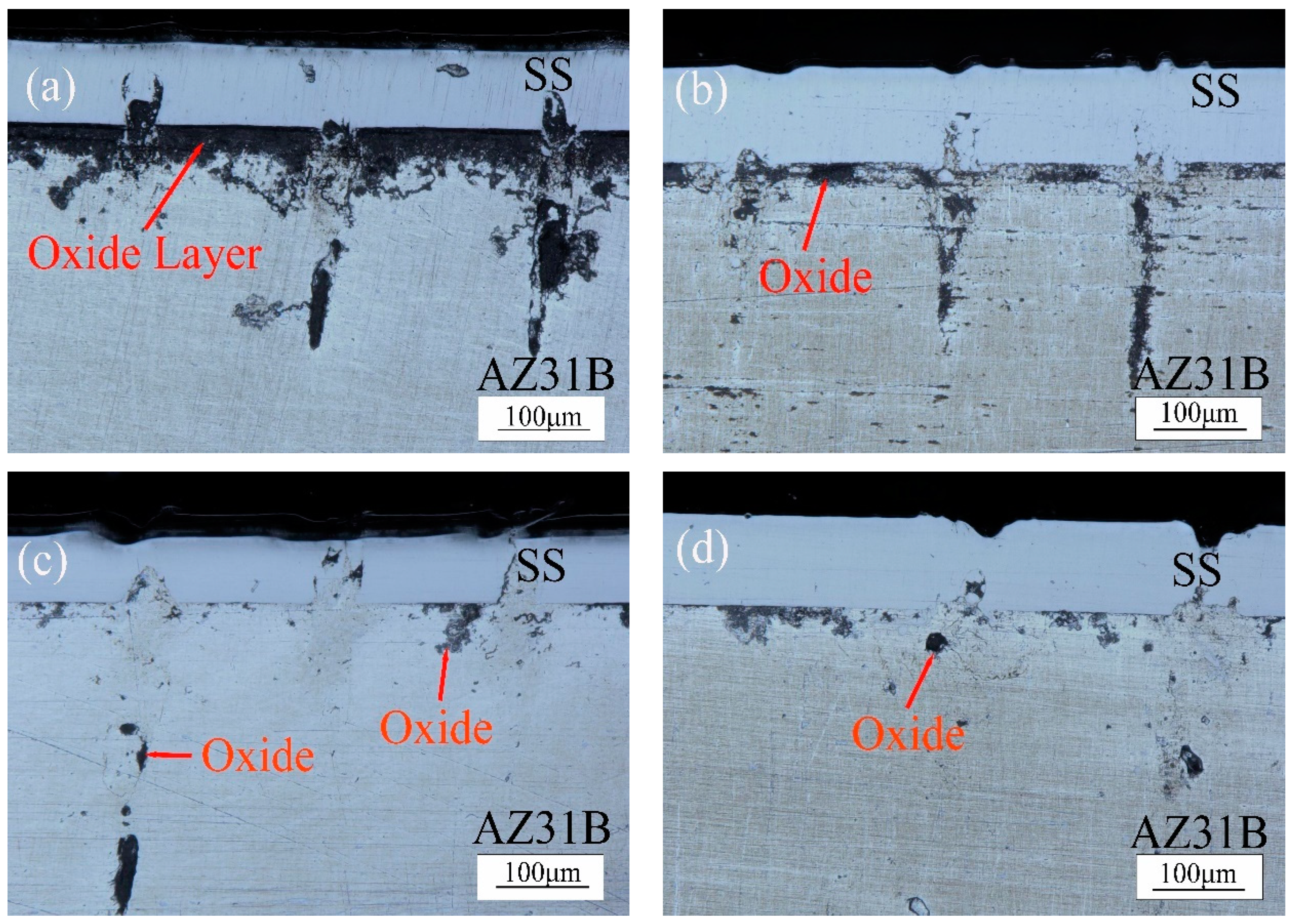
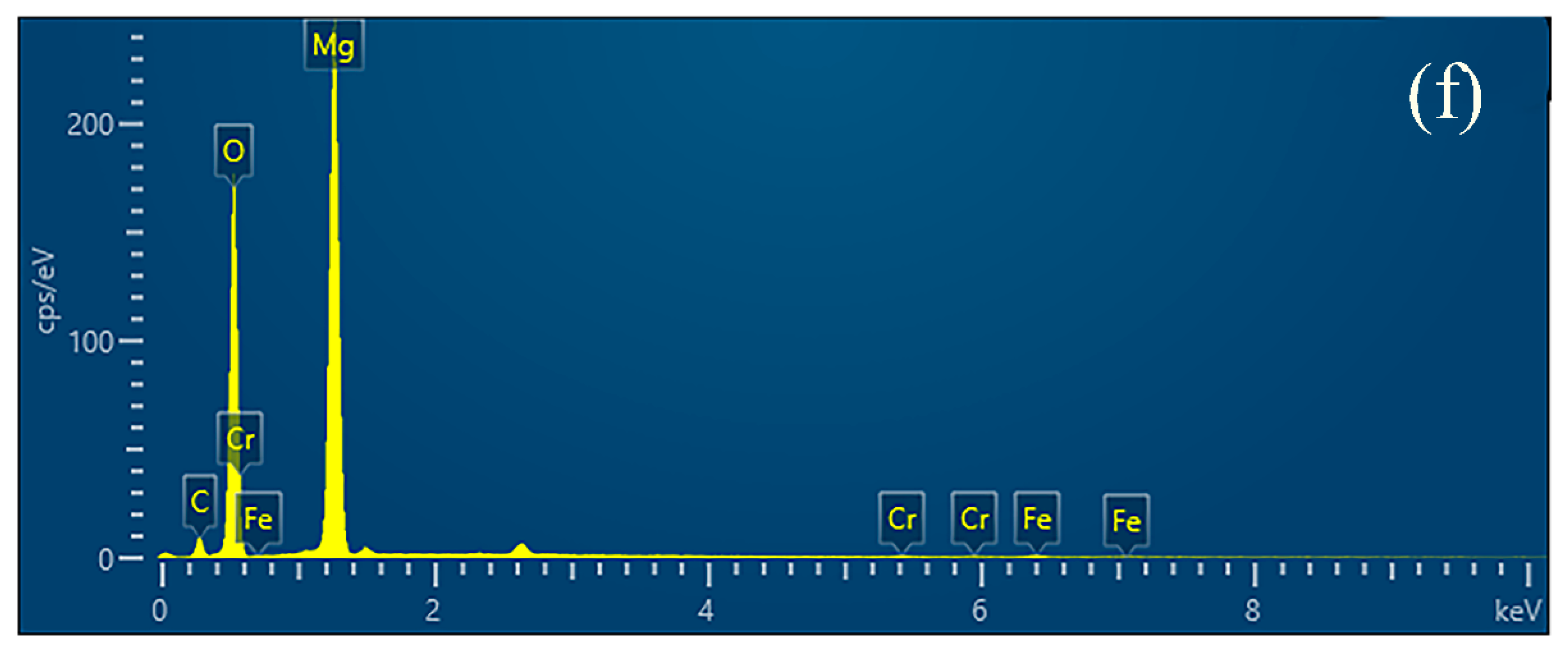
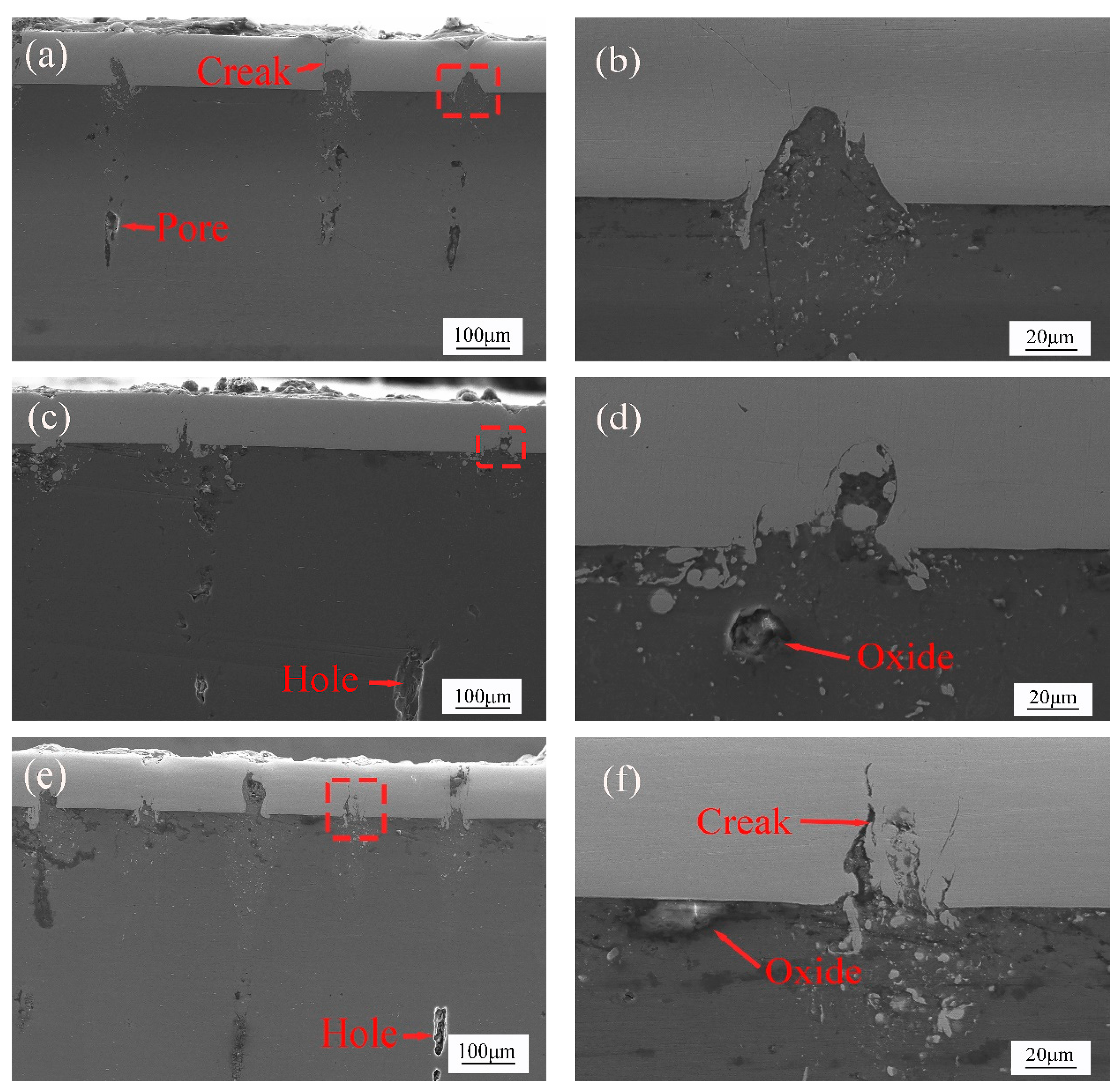
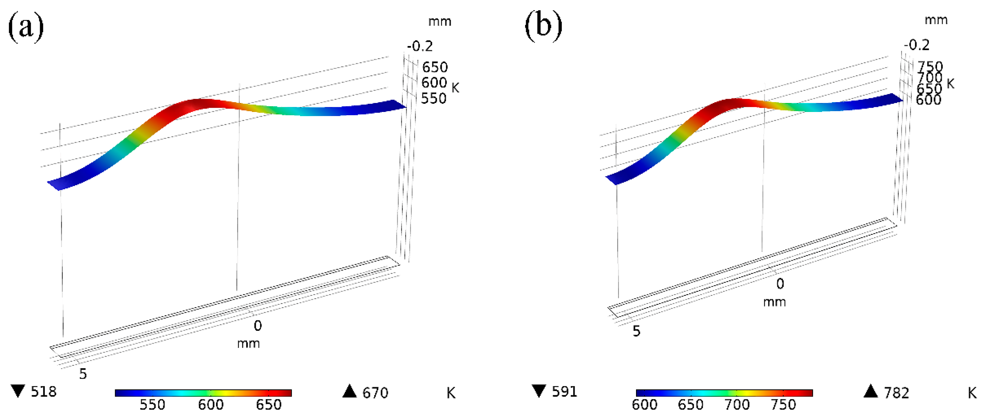
- When the laser power is 15 W and 20 W, because of the low laser power, MgO slag inclusion exists between magnesium and steel, and hot cracks appear on the steel side. The welding effects of magnesium and steel are poor. From the distribution of the temperature field, we observe this in the same section at 1.8431 s after welding. At 15 W-20 W, the temperature did not reach the melting point of magnesium alloy, resulting in poor adhesion between the steel plate and the magnesium plate.
- (2)
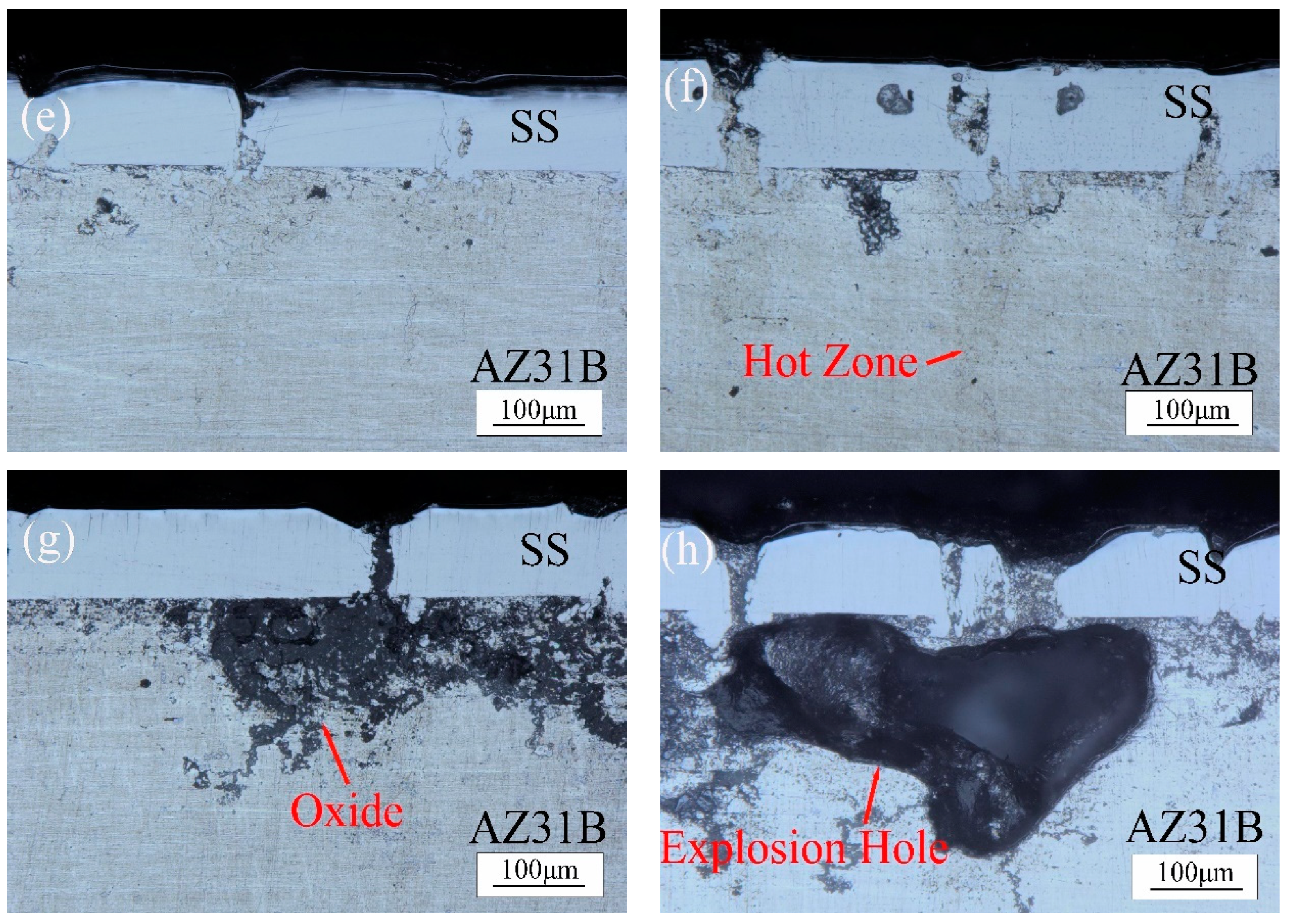
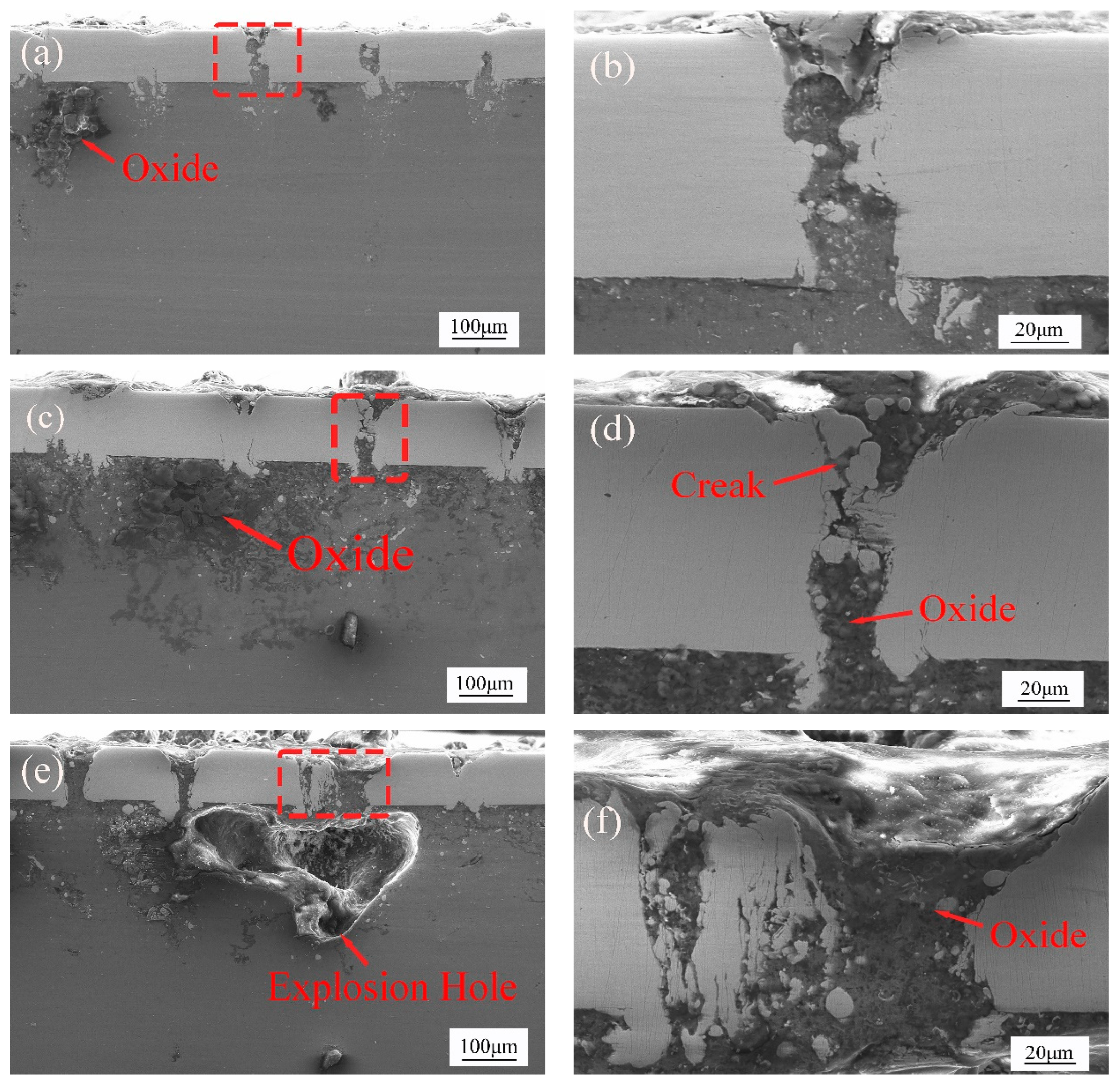
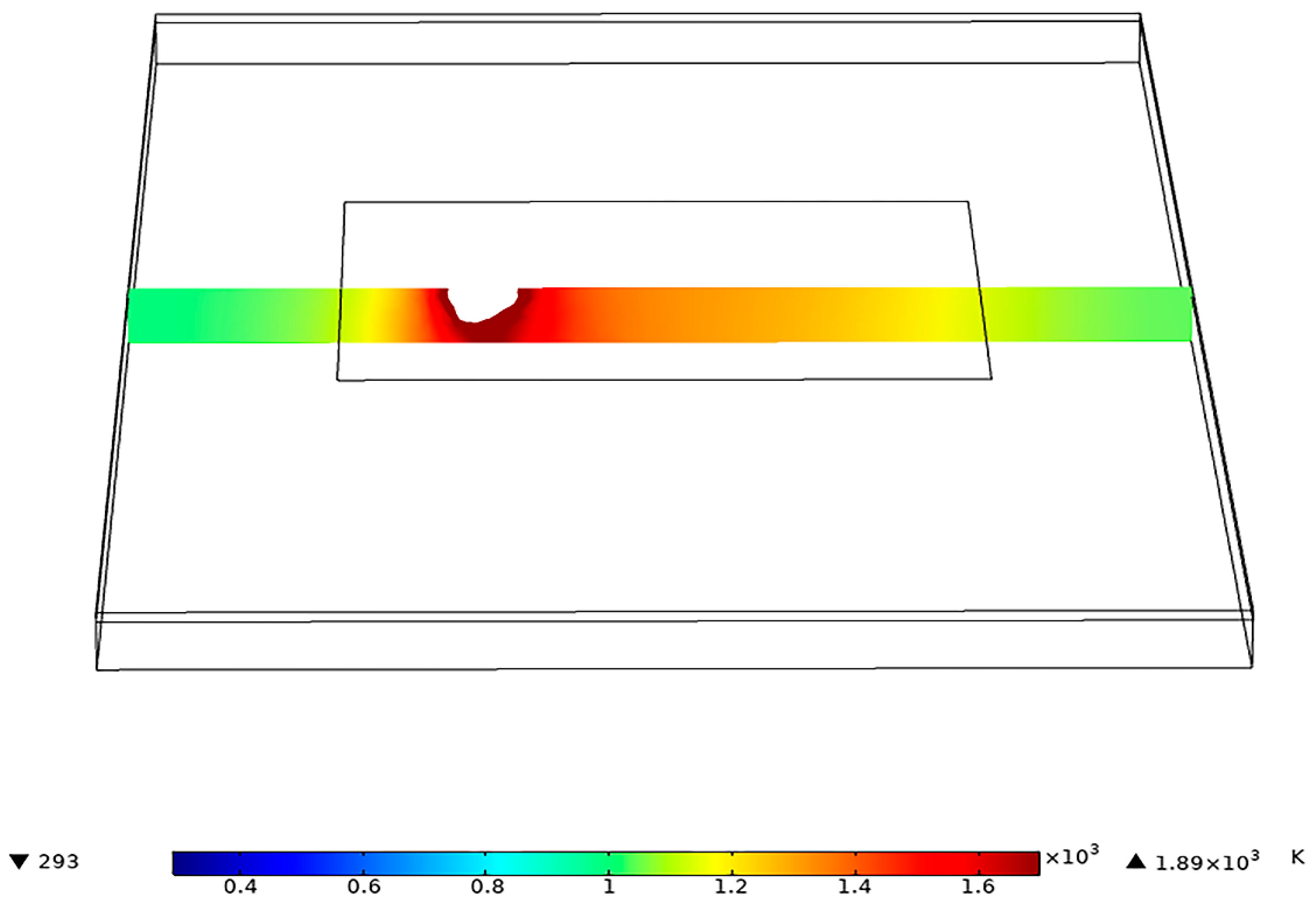
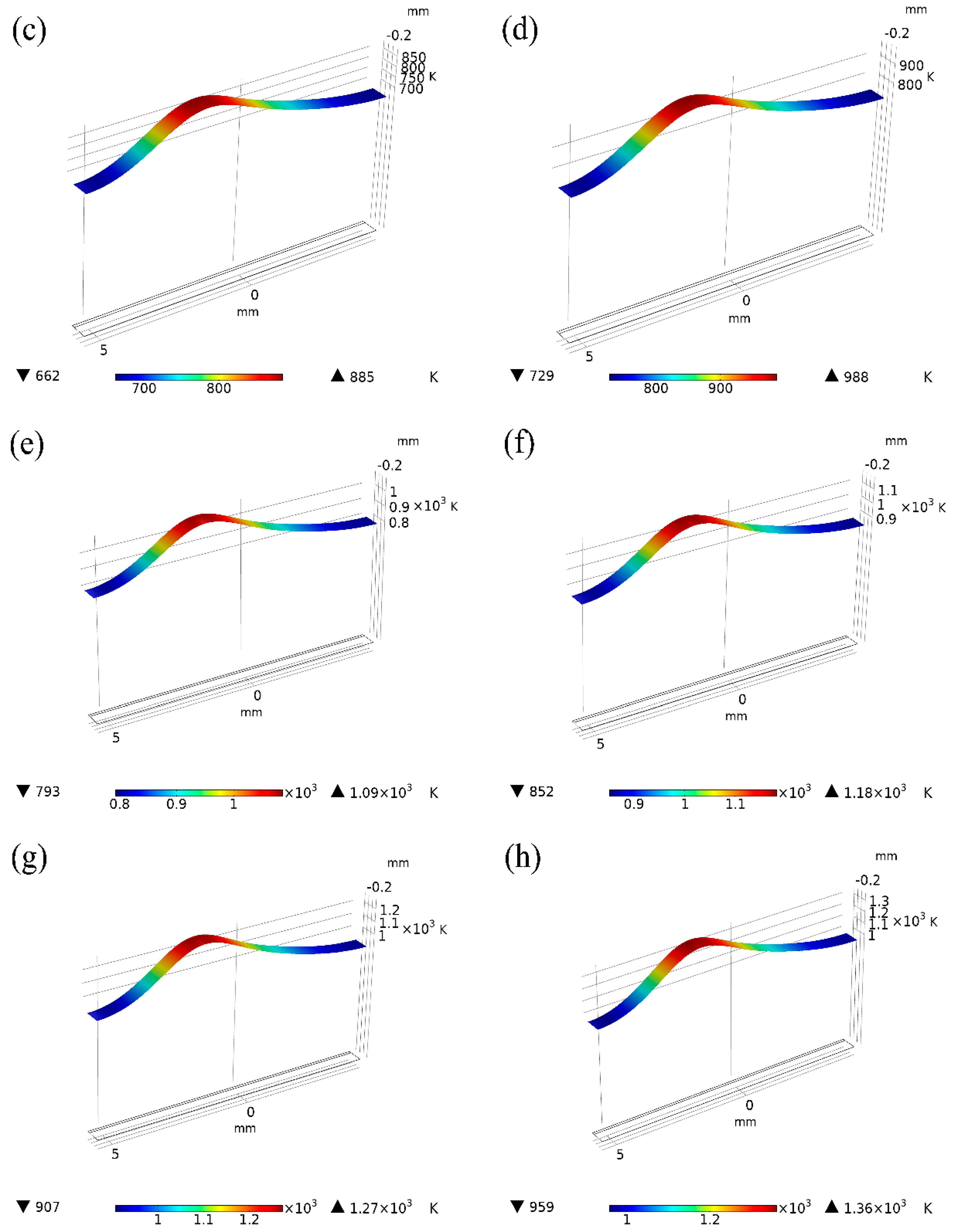
- When the laser power is 35 W–50 W, due to the high temperature, the depth of the magnesium intrusion into the steel side increases, resulting in poor joint strength. The depth of the thermal reaction zone becomes deeper, resulting in the formation of thermal cracks, pores, and oxides. Meanwhile, laser welding near the center will form an explosion hole and thermal crack defects, resulting in poor strength of the joint.
- (3)
- When the power is 25 W and 30 W, the temperature is between the melting point and boiling point of the magnesium. The depth of the magnesium intrusion to the steel side is appropriate, and there is no MgO inclusion at the joint between magnesium and steel, which has good joint strength and good welding interface bonding.
Author Contributions
Funding
Institutional Review Board Statement
Informed Consent Statement
Data Availability Statement
Conflicts of Interest
References
- Cao, X.; Jahazi, M.; Immarigeon, J.P.; Wallace, W. A review of laser welding techniques for magnesium alloys. J. Mater. Process. Tech. 2006, 171, 188–204. [Google Scholar] [CrossRef]
- Chalisgaonkar, R. Insight in applications, manufacturing and corrosion behaviour of magnesium and its alloys—A review. Mater. Today Proc. 2020, 26, 1060–1071. [Google Scholar] [CrossRef]
- Ferreira, V.; Merchán, M.; Egizabal, P.; de Cortázar, M.G.; Irazustabarrena, A.; López-Sabirón, A.M.; Ferreira, G. Technical and environmental evaluation of a new high performance material based on magnesium alloy reinforced with submicrometre-sized TiC particles to develop automotive lightweight components and make transport sector more sustainable. J. Mater. Res. Technol. 2019, 8, 2549–2564. [Google Scholar] [CrossRef]
- Golroudbary, S.R.; Makarava, I.; Repo, E.; Kraslawski, A.; Luukka, P. Magnesium Life Cycle in Automotive Industry. Procedia CIRP 2022, 105, 589–594. [Google Scholar] [CrossRef]
- Joost, W.J.; Krajewski, P.E. Towards magnesium alloys for high-volume automotive applications. Scripta Mater. 2017, 128, 107–112. [Google Scholar] [CrossRef]
- Xiang, Y.; Wang, X.; Shi, H.; Hu, X.; Xu, C.; Zhang, Q. Decipher the ultra-high strengthening and toughening efficiency of GNS-MgO/Mg layered composite with in-situ enhanced interface. Carbon 2022, 196, 783–794. [Google Scholar] [CrossRef]
- Zhang, S.; Wu, R.; Zhong, F.; Ma, X.; Wang, X.; Wu, Q. Ultra-high strength Mg-Li alloy with B2 particles and spinodal decomposition zones. Fund. Res. 2022; in press. [Google Scholar] [CrossRef]
- Zhou, H.; Liu, J.-S.; Zhou, D.-W.; Tao, T. Effect of Al-foil addition on microstructure and temperature field of laser fusion welded joints of DP590 dual-phase steel and AZ31B magnesium alloy. Trans. Nonferrous Met. Soc. China 2020, 30, 2669–2680. [Google Scholar] [CrossRef]
- Liu, L.; Qi, X. Strengthening effect of nickel and copper interlayers on hybrid laser-TIG welded joints between magnesium alloy and mild steel. Mater. Des. 2010, 31, 3960–3963. [Google Scholar] [CrossRef]
- Wahba, M.; Katayama, S. Laser welding of AZ31B magnesium alloy to Zn-coated steel. Mater. Des. 2012, 35, 701–706. [Google Scholar] [CrossRef]
- Casalino, G.; Guglielmi, P.; Lorusso, V.D.; Mortello, M.; Peyre, P.; Sorgente, D. Laser offset welding of AZ31B magnesium alloy to 316 stainless steel. J. Mater. Process. Tech. 2017, 242, 49–59. [Google Scholar] [CrossRef]
- Tao, T.; Liu, J.; Zhou, D.; Li, C.; Li, H. Microstructure and mechanical properties of laser welding of AZ31B magnesium alloy and DP590 dual-phase steel with concave groove joint. J. Manuf. Process. 2021, 72, 227–239. [Google Scholar] [CrossRef]
- Fu, B.; Shen, J.; Suhuddin, U.F.; Pereira, A.A.; Maawad, E.; dos Santos, J.F.; Klusemann, B.; Rethmeier, M. Revealing joining mechanism in refill friction stir spot welding of AZ31 magnesium alloy to galvanized DP600 steel. Mater. Des. 2021, 209, 109997. [Google Scholar] [CrossRef]
- Hao, K.; Wang, H.; Gao, M.; Wu, R.; Zeng, X. Laser welding of AZ31B magnesium alloy with beam oscillation. J. Mater. Res. Technol. 2019, 8, 3044–3053. [Google Scholar] [CrossRef]
- He, Z.; Wang, H.; Gao, M.; Wu, R.; Zeng, X. Hybrid joining mechanism of rivet plug oscillating laser welding for dual-phase steel and magnesium alloy. J. Manuf. Process. 2022, 77, 652–664. [Google Scholar] [CrossRef]
- Kotari, S.; Punna, E.; Gangadhar, S.M.; Cheepu, M.; Sarkar, P.; Venukumar, S. Dissimilar metals TIG welding-brazing of AZ31 magnesium alloy to 304 stainless steel. Mater. Today Proc. 2021, 39, 1549–1552. [Google Scholar] [CrossRef]
- Lee, C.T.; Han, S.W.; Shin, M.W. Application of nanosecond laser to a direct and rapid growth of Cu-BTC metal-organic framework thin films on copper substrate. Surf. Interfaces 2022, 30, 101904. [Google Scholar] [CrossRef]
- Li, G.; Lu, X.; Zhu, X.; Guo, Y.; Song, J. Fiber laser butt joining of AZ31B alloy to 304 stainless steels with copper foil. Opt. Laser Technol. 2019, 117, 215–226. [Google Scholar] [CrossRef]
- Liu, Z.; Jin, X.; Zhang, J.; Hao, Z.; Li, J. Microstructure evolution and mechanical properties of SUS301L stainless steel sheet welded joint in ultrasonic vibration assisted laser welding. Opt. Laser Technol. 2022, 153, 108193. [Google Scholar] [CrossRef]
- Liu, Z.; Yang, W.; He, X.; Cheng, T.; Huang, H.; Xiong, J.; Huang, G. Synthesis of a green inhibitor and its inhibition behavior on AZ91D magnesium alloy in distilled water. Surf. Interfaces 2022, 30, 101870. [Google Scholar] [CrossRef]
- Meng, C.; Zhang, Z.; Yang, J.; Zhuang, W.; Shi, H. Effect of laser bionic treatment on fatigue crack growth behavior of TIG welded AZ31B magnesium alloy joint. Mater. Lett. 2022, 320, 132334. [Google Scholar] [CrossRef]
- Qi, X.; Song, G. Interfacial structure of the joints between magnesium alloy and mild steel with nickel as interlayer by hybrid laser-TIG welding. Mater. Des. 2010, 31, 605–609. [Google Scholar] [CrossRef]
- Shu, F.; Niu, S.; Zhu, B.; Wu, L.; Xia, H.; Chen, B.; Zhao, J.; Tan, C. Influence of scan line spacing on nanosecond pulse laser welding of 6063 Al to steel thin sheets. Opt. Laser Technol. 2022, 145, 107497. [Google Scholar] [CrossRef]
- Xia, H.; Ma, Y.; Chen, C.; Su, J.; Zhang, C.; Tan, C.; Li, L.; Geng, P.; Ma, N. Influence of laser welding power on steel/CFRP lap joint fracture behaviors. Compos. Struct. 2022, 285, 115247. [Google Scholar] [CrossRef]
- Yuan, T.; Zhang, H.; Jiang, X.; Chen, S.; Xu, M.; Liu, X. Investigation on liquation cracks of dissimilar magnesium alloy welds using the circular-patch experiment and numerical simulation. J. Manuf. Process. 2022, 75, 49–59. [Google Scholar] [CrossRef]
- Yuan, G.; Li, X.; Liu, Z.; Zhang, J.; Zhou, Z.; Zhou, S.; Long, Y. Laser welding of carbon-fibre-reinforced polyetherketone and 304 stainless steel: Cost-effective approach using prefabricated holes. Opt. Laser Technol. 2022, 152, 108185. [Google Scholar] [CrossRef]
- Zhang, X.; Bian, S.; Zhao, P.; Ding, X.; Li, Y.; Cao, Z. Investigation on pore formation in pulsed laser spot welding of AZ31 magnesium alloy. Opt. Laser Technol. 2022, 149, 107894. [Google Scholar] [CrossRef]
- Halim, S.B.; Bannour, S.; Abderrazak, K.; Kriaa, W.; Autric, M. Numerical analysis of intermetallic compounds formed during laser welding of aluminum-magnesium dissimilar couple. Therm. Sci. Eng. Prog. 2021, 22, 100838. [Google Scholar] [CrossRef]
- Huang, L.; Hua, X.; Wu, D.; Li, F. Numerical study of keyhole instability and porosity formation mechanism in laser welding of aluminum alloy and steel. J. Mater. Process. Technol. 2018, 252, 421–431. [Google Scholar] [CrossRef]
- Tao, T.; Zhou, D.; Liu, J.; Wang, X. Improvement of laser welded joint properties of AZ31B magnesium alloy to DP590 dual-phase steel produced by external magnetic field. J. Manuf. Process. 2022, 79, 270–283. [Google Scholar] [CrossRef]
- Yan, S.; Meng, Z.; Chen, B.; Tan, C.; Song, X.; Wang, G. Prediction of temperature field and residual stress of oscillation laser welding of 316LN stainless steel. Opt. Laser Technol. 2022, 145, 107493. [Google Scholar] [CrossRef]
- Huo, P.D.; Li, F.; Wang, Y.; Wu, R.Z.; Gao, R.H.; Zhang, A.X. Annealing coordinates the deformation of shear band to improve the microstructure difference and simultaneously promote the strength-plasticity of composite plate. Mater. Des. 2022, 219, 110696. [Google Scholar] [CrossRef]
- Ma, X.-C.; Jin, S.-Y.; Wu, R.-Z.; Wang, J.-X.; Wang, G.-X.; Krit, B.; Betsofen, S. Corrosion behavior of Mg−Li alloys: A review. Trans. Nonferrous Met. Soc. China 2021, 31, 3228–3254. [Google Scholar] [CrossRef]
- Wang, D.; Liu, S.; Wu, R.; Zhang, S.; Wang, Y.; Wu, H.; Zhang, J.; Hou, L. Synergistically improved damping, elastic modulus and mechanical properties of rolled Mg-8Li-4Y–2Er-2Zn-0.6Zr alloy with twins and long-period stacking ordered phase. J. Alloys Compd. 2021, 881, 160663. [Google Scholar] [CrossRef]
- Li, X.; Wang, X.; Hu, X.; Xu, C.; Shao, W.; Wu, K. Direct conversion of CO2 to graphene via vapor–liquid reaction for magnesium matrix composites with structural and functional properties. J. Magnes. Alloy. 2021; in press. [Google Scholar] [CrossRef]
- Jin, S.; Ma, X.; Wu, R.; Li, T.; Wang, J.; Krit, B.L.; Hou, L.; Zhang, J.; Wang, G. Effect of carbonate additive on the microstructure and corrosion resistance of plasma electrolytic oxidation coating on Mg-9Li-3Al alloy. Int. J. Miner. Met. Mater. 2022, 29, 1453–1463. [Google Scholar] [CrossRef]


| Sample | Al | C | Si | Mn | P | Cr | Ni | Mg | Fe |
|---|---|---|---|---|---|---|---|---|---|
| 304SS | - | 0.021 | 0.386 | 1.462 | 0.031 | 18.137 | 8.064 | - | Bal. |
| AZ31B | 3.00 | - | 0.02 | 0.31 | - | - | - | Bal. | 0.005 |
| Metal | Melting Point (K) | Coefficient of Thermal Conductivity (W·m−1·k−1) | Density (kg·m−3) |
|---|---|---|---|
| 304SS | 1671.15~1727.15 | 21.5 | 7850 |
| AZ31B | 923.15 | 155.5 | 1738 |
| Welding Parameters | Value |
|---|---|
| Welding speed (mm/s) | 30 |
| Frequency (kHz) | 20 |
| Sweep line spacing (mm) | 0.2 |
| The pulse width (ns) | 10 |
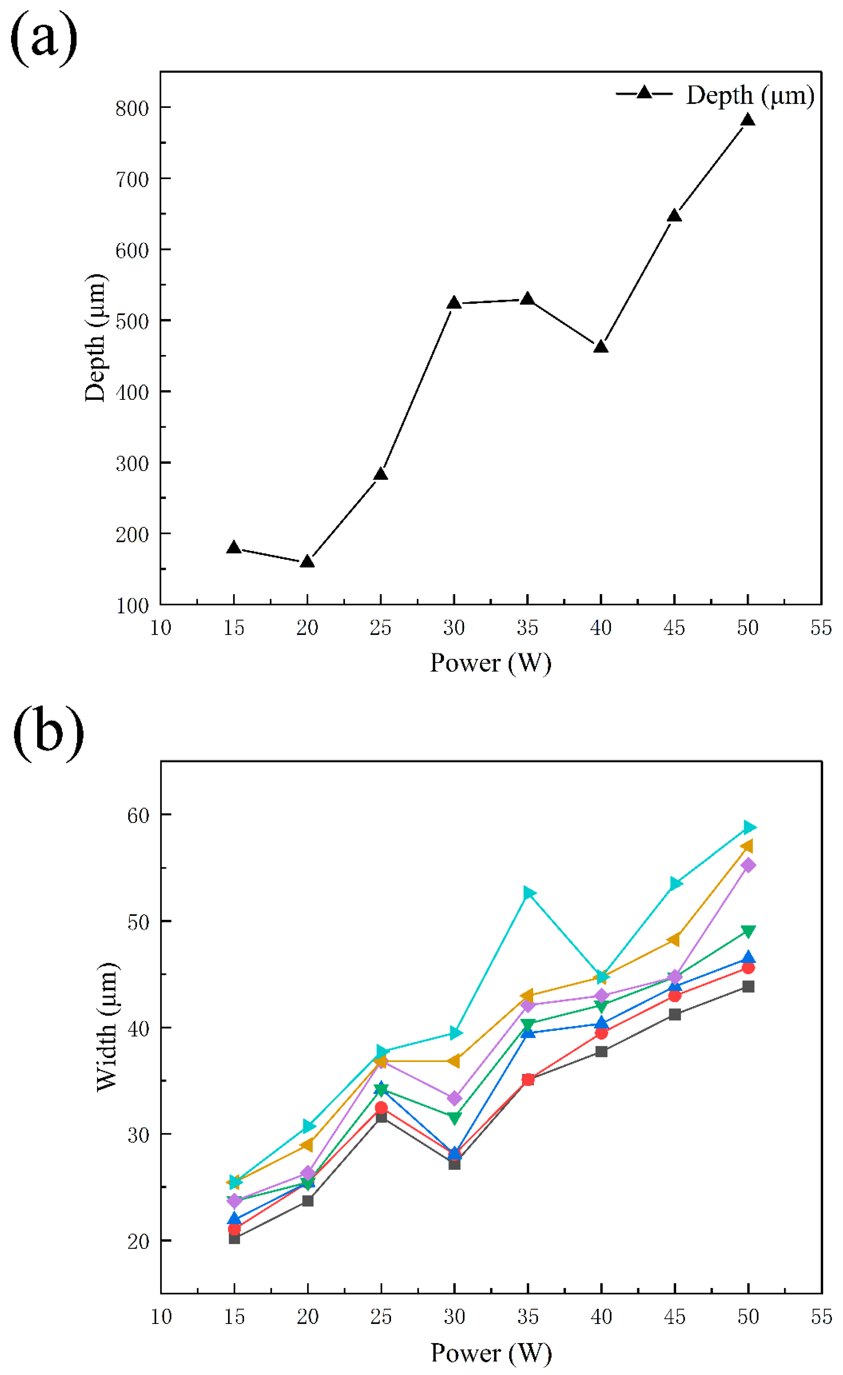
| Power (W) | 15, 20, 25, 30, 35, 40, 45, 50 |
Publisher’s Note: MDPI stays neutral with regard to jurisdictional claims in published maps and institutional affiliations. |
© 2022 by the authors. Licensee MDPI, Basel, Switzerland. This article is an open access article distributed under the terms and conditions of the Creative Commons Attribution (CC BY) license (https://creativecommons.org/licenses/by/4.0/).
Share and Cite
Wu, Z.; Wan, J.; Zhang, Y.; Xue, B.; Wu, R.; Yang, C. Effect of Laser Welding Parameters on Joint Structure of AZ31B Magnesium Alloy and 304 Stainless Steel. Materials 2022, 15, 7114. https://doi.org/10.3390/ma15207114
Wu Z, Wan J, Zhang Y, Xue B, Wu R, Yang C. Effect of Laser Welding Parameters on Joint Structure of AZ31B Magnesium Alloy and 304 Stainless Steel. Materials. 2022; 15(20):7114. https://doi.org/10.3390/ma15207114
Chicago/Turabian StyleWu, Zhe, Jiaqi Wan, Yang Zhang, Bo Xue, Ruizhi Wu, and Chunmei Yang. 2022. "Effect of Laser Welding Parameters on Joint Structure of AZ31B Magnesium Alloy and 304 Stainless Steel" Materials 15, no. 20: 7114. https://doi.org/10.3390/ma15207114
APA StyleWu, Z., Wan, J., Zhang, Y., Xue, B., Wu, R., & Yang, C. (2022). Effect of Laser Welding Parameters on Joint Structure of AZ31B Magnesium Alloy and 304 Stainless Steel. Materials, 15(20), 7114. https://doi.org/10.3390/ma15207114