Article

Metal Knitting: A New Strategy for Cold Gas Spray Additive Manufacturing

1
Thermal Spray Centre CPT, Universitat de Barcelona, Carrer Martí i Franques 1, 7a planta, 08028 Barcelona, Spain
2
Cátedras CONACyT—Centro de Ingeniería y Desarrollo Industrial (CIDESI), Av. Playa Pie de la Cuesta No. 702, Desarrollo San Pablo, Santiago de Querétaro C.P. 76125, Mexico
*
Author to whom correspondence should be addressed.
Materials 2022, 15(19), 6785; https://doi.org/10.3390/ma15196785
Submission received: 25 August 2022 / Revised: 19 September 2022 / Accepted: 26 September 2022 / Published: 30 September 2022

Abstract

:
Cold Spray Additive Manufacturing (CSAM) is an emergent technique to produce parts by the additive method, and, like other technologies, it has pros and cons. Some advantages are using oxygen-sensitive materials to make parts, such as Ti alloys, with fast production due to the high deposition rate, and lower harmful residual stress levels. However, the limitation in the range of the parts’ geometries is a huge CSAM con. This work presents a new conceptual strategy for CSAM spraying. The controlled manipulation of the robot arm combined with the proper spraying parameters aims to optimize the deposition efficiency and the adhesion of particles on the part sidewalls, resulting in geometries from thin straight walls, less than 5 mm thick, up to large bulks. This new strategy, Metal Knitting, is presented regarding its fundamentals and by comparing the parts’ geometries produced by Metal Knitting with the traditional strategy. The Metal Knitting described here made parts with vertical sidewalls, in contrast to the 40 degrees of inclination obtained by the traditional strategy. Their mechanical properties, microstructures, hardness, and porosity are also compared for Cu, Ti, Ti6Al4V, 316L stainless steel, and Al.

1. Introduction

Manufacturing industry is always looking for new cost-effective processes showing minimal raw material consumption, zero waste generation, and minimum energy consumption. Therefore, it promotes the rise of sustainable and more efficient technologies capable of responding to these needs [1]. During recent decades, many alternatives to traditional production methods have arisen in the market with the capabilities to fabricate unique components made in special alloys, which are not feasible by the conventional fabrication processes due to production complexity, properties, or even the high costs [2]. Beginning with polymer 3D printing in the 1980s and advancing its concept to producing metallic parts, the Additive Manufacturing (AM) techniques have expanded greatly in this period. They have been presented as an alternative to satisfy some of the above-mentioned industry and societal needs. A simple research in Scopus’ database can demonstrate the relevance of these technologies, where the number of documents published per year using the query “additive AND manufactur*” has grown from 278 works in 2000 to 781 in 2010 and then 10,751 in 2021, an extraordinary increase of 1300% in only one decade.
In the case of metallic AM components, some processes have become widespread, such as arc welding, laser melting or sintering, and cold gas spray (CS), among other methods [3,4,5]. Each process has different characteristics, limitations, or pros and cons, e.g., laser processes can produce very complex geometries but slowly and generate tensile residual stress in the material [6]. The welding or assembling of small AM individual parts is proposed in the literature as the best option to produce a large component [7]. However, this welding may result in distortion, shrinkage, or high tensile residual stress in the final AM part. Nevertheless, most of these AM techniques are based on the melting of raw material, which is an issue for some materials, such as the oxygen-sensitive Ti alloys, limiting the application of the technology.

1.1. Cold Gas Spray as an Additive Manufacturing Process

CS is a method of depositing powdered materials in the solid state, in which the cohesion of powder particles in the deposit is generated because of their impact under supersonic velocity onto a substrate/surface. For this, the CS equipment heats a gas in a chamber, discharging it under high pressure through a De Laval nozzle and accelerating it to supersonic velocity, dragging the feedstock powder under its recrystallization temperature [8,9].
The literature presents the application of CS for AM for a large number of materials, highlighting the components made from 316L stainless steel [10,11,12,13,14], Cu alloys [15,16,17], and Ti alloys [18,19,20,21], but not limited to them since Al alloys [21,22,23,24], Ni superalloys [25,26], maraging steel [27,28,29], and many others have also been studied. Moreover, these CSAM components have interested different sectors, such as aerospace, automotive, energy, medical, and marine sectors, among others [8,30]. In this sense, Prashar and Vasudev [31] list the CSAM benefits for sustainable manufacturing: optimizing product structures and designs, no environmental effect, component restoration rather than replacement, and improving the valuable life service of the component. The scientific interest in CSAM can be confirmed by a simple search in Scopus’ database searching by the query “additive AND manufactur* AND cold AND spray*” OR “3d AND print* AND cold AND spray*”, resulting in zero documents until 2011, 12 in 2015, 86 in 2020, and 81 in 2021, increasing by 675% the number of documents in the last five years.
In recent years, most of these studies have focused on CS mechanical properties and high deposition efficiency (DE). DE is the ratio between the CS sprayed powder mass and the consolidated part mass, which is directly influenced by the velocity reached by the particles when impinging the surface. Regarding CS parameters, adjustments and variations in CS working gas temperature and pressure, the nozzle design and geometry, and the spraying stand-off distance have been effective for improving the DE particle cohesion. It is widely accepted that the sprayed particles have to impact the substrate with a velocity between a critical or minimum and a maximum limit value.

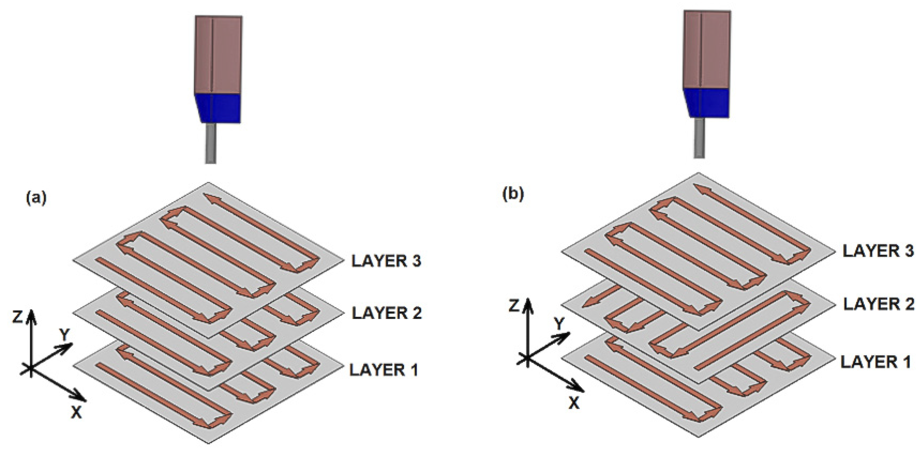
1.2. CSAM Deposition Strategies

The traditional strategy used in CS for powder deposition is based on a linear and normal movement of the CS gun with respect to the substrate surface, which might repeat for depositing consecutive layers, or alternating this direction, as presented by arrows in Figure 1. This extended deposition strategy promotes the growth of CSAM part sidewalls off-normal angle with the substrate surface, which limits the use of CSAM to near-net-shape components production that should finally be post-machined until the desired geometry and dimensions are obtained. The inclination shown by CSAM part sidewalls usually leads to more or less slope depending on the material sprayed, CS spraying parameters, or the substrate geometry, such as spraying on its flat surface or edges. The literature presents some approaches to developing a suitable deposition strategy for CSAM. For instance, some authors have proposed that it is possible to compensate this inclination in consecutive spraying tests, making the particles laden jet perpendicular to this inclined surface [32,33,34], Figure 2. Here, it is mandatory to know the inclination angle of the growth sidewall and redress the geometry at the end. However, this strategy is not feasible when thin walls are intended. In addition, the modification of the spraying directions generates new interfaces in which the cohesion of the particles is weaker, promoting an inhomogeneity of final component properties.
The use of CSAM has grown in recent years. Some researchers have developed strategies to control the CSAM parts geometries, mainly regarding sidewall inclinations because this is a considerable limitation for CSAM in producing freeform parts. The presence of undesired sidewall inclination represents a loss of spraying time and raw material, besides needing more post-machining time. An efficient alternative seen in the literature is the correction of the sidewall inclination by a sequence of layers with different CS jetting angles, Figure 2. However, it demands a specific robot strategy or parameters for each material and CS spraying condition. Thus, in this work, the authors aim to present the effectiveness of using a new CSAM deposition strategy in substitution for the CSAM traditional strategy commonly used. The strategies are compared not only by the CSAM geometries produced, mainly the sidewall angles inclination, but they are also evaluated regarding the microstructures obtained, and their physical and mechanical properties. The novelty in the Metal Knitting strategy is developing a robot strategy capable of producing thin vertical walls or large bulks, thereby eliminating geometry correction steps, which are demanded when using the traditional strategy.

2. Materials and Methods

316L stainless steel, pure Cu, pure Al, Ti grade 2 (pure Ti), and Ti grade 5 (Ti6Al4V) powders were sprayed using the newly developed and traditional CS strategies. Irregular and spherical water atomized powder were used in these tests in order to show the capabilities for generating controlled geometries by Metal Knitting using powder with different morphologies. The feedstock powders’ particle size distribution was measured by laser scattering in LS13320 (Beckman Coulter, Brea, CA, USA), and the particles’ shapes were interpreted from SEM images obtained in equipment Pro Desktop (Phenon, Eindhoven, The Netherlands). The feedstock powders’ chemical composition was measured by Inductively Couple Plasma (ICP) in equipment Optima ICP-OES 3200 RL (Perkin Elmer, Waltham, MA, USA) and is presented in Table 1.
The five feedstock powders for CSAM have the shapes obtained by SEM presented in Figure 3, where it is possible to see the typical irregular shape for the water-atomized ones, 316L and Al, as well as the spherical gas-atomized Ti alloys and pure Cu. The powder size distribution is also presented in Figure 4, which is quite similar for all the powders and is in the range optimal for CS processes because particles out of this range may not reach the optimal velocity at the impact on the substrate [35,36].
Regarding the particle shape, the water-atomized 316L and Al are cheaper options than gas-atomization powders since the production costs are lower for this manufacturing process. The raw material price is an important factor when applying the CSAM technique due to its heavy impact on the part‘s final costs. Previously, Vaz et al. [10] presented for CS 316L coatings the quite similar performance of gas-atomized and water-atomized powders, regarding mechanical properties, wear resistance, and corrosion behavior. It supports the selection of the irregular powder used in this article.
The CSAM depositions were performed using PCS100 equipment(Plasma Giken, Saitama, Japan) and N2 as working gas. The main spraying parameters are indicated in Table 2. The robot was an IRB 2400 M2004 (ABB, Västerås, Sweden) and the programming was performed in ABB RobotStudio v6.08.01 software. The PCS100 gun was kept static while the sample holder performed all the robot arm movements. For the CSAM samples deposited by the traditional strategy, the robot path followed the Figure 1a scheme, with velocity of 500 mm·s−1.
The CSAM parts produced were evaluated regarding the geometries obtained, sidewall angles, and visual characteristics. In addition, a visual inspection was performed to find CSAM part imperfections, such as cracks, delamination between the layers, and adhesion to the substrate, among others. The microhardness of samples was measured by means of HMV equipment, applying a load of 0.3 kgf (HV0.3) and presenting a mean value of 10 values for each sample. The metallographic preparation was carried out in accordance with the ASTM E1920-03 and ASTM E3-01 standards, and the porosity was analyzed from light microscopy images obtained in Leica DMI3000 M microscope at 200× g magnification, according to ASTM E2109-01 standard. For tensile testing, three samples of each CSAM part were manufactured by the wire Electrical Discharge Machining (EDM) process. A Zmart.Pro equipment(ZwickRoell, Eisengen, Germany) with an Xforce P 10 kN load cell was used for the tensile testing, with a load application velocity of 1.0 mm·min−1.

3. Results and Discussions

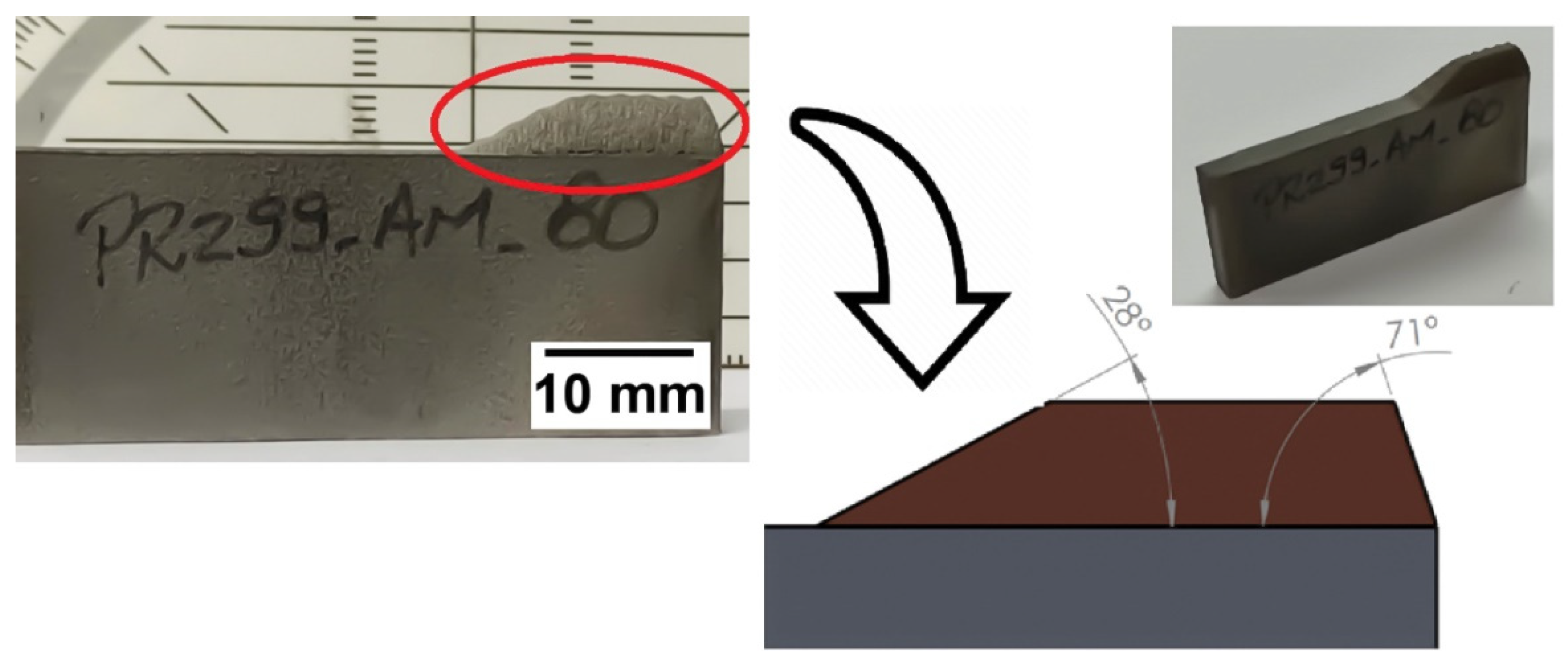
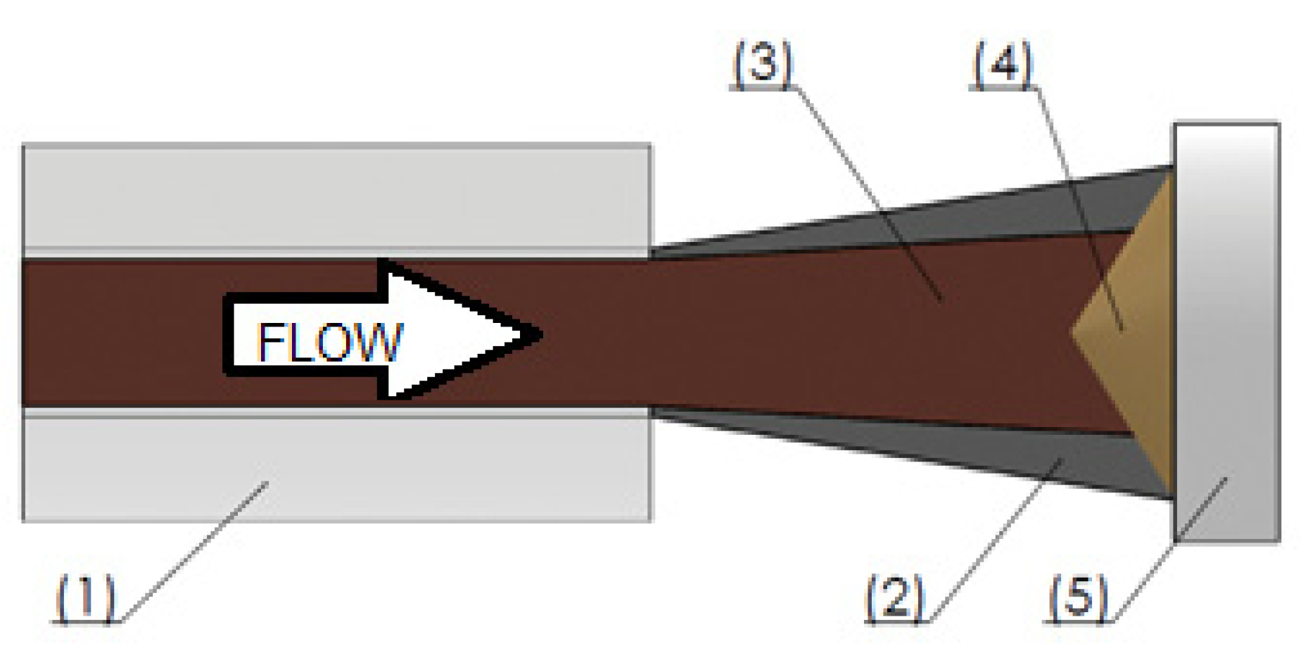
3.1. Influence of Substrate Shape on CSAM Part Geometry

Before evaluating the effect of the new strategy for geometric control of CSAM deposits, 316L deposits using an irregular powder were produced by the traditional strategy that will be considered a CSAM benchmark for the Metal Knitting samples evaluations. Figure 5 shows a CSAM 316L deposit sprayed onto a carbon steel plate’s thinnest face (5 mm) to highlight the effect of the traditional spraying strategy on the inclination of the sidewalls generated. Here, it can be observed that the CSAM sidewalls inclinations are different for each substrate area or region scanned, considering the substrate’s edge or flat surface. For example, from the substrate’s edge, the CSAM 316L part grew up at 71 degrees relative to the substrate’s flat face, while it grew at an angle of 28 degrees from a flat surface. Table 3 shows the sidewall angles obtained for 316L, Al, Cu, Ti, and Ti6Al4V as well. These results indicate that this inclination effect is dependent on the powder material sprayed, and not limited to stainless steel or irregular feedstock materials.
It is widely accepted that the velocity and the density of particles in the center of CS particles laden jet flow are higher than in its periphery [9,24,37,38,39]. A lower velocity and number of particles in the periphery of the CS particles laden jet produce a progressive thinner layer at the border of the sprayed layer (Figure 6), promoting a thickness distribution or single-track profile defined by a Gaussian distribution [40]. This effect explains the inclined sidewalls commonly obtained by the traditional spraying strategy in CSAM. The behaviour observed in different regions of the substrate is explained by considering the geometric features of the sample [38,41] since, for a deposition in a substrate edge, the CS particle plume passes completely through this edge, finishing its travel out of the sample, where the robot changes the direction and turns back to another pass. However, this does not occur for the deposition on a flat surface, where particle distribution in the CS particle plume always affects the formation and consolidation of CSAM part geometry because all the changes in robot movement directions are done on the substrate surface.
Besides considering the density of particles in different positions of the CS plume, it is worth considering that the farther the particles are radially from the jet center, the lower their velocities are, Figure 6. It is well known that the CS deposition and the part consolidation depend strongly on the velocity of the particles [42,43,44], but radially just a few millimetres from the CS jet center, the particles present a severe reduction in velocity, even to out of the CS deposition window of velocity. Previous CFD simulations by several authors have predicted this behavior under specific CS parameters. For example, Al and Ti particles have a velocity of 700 m·s−1 close to the particles laden jet center, but radially 4 mm far from this center, the velocity falls to 500 m·s−1, a reduction of almost 30% [45,46,47]. For 316L, this trend is the same [48], which influences the CSAM part consolidated geometry.
Consequently, a not constant particles-laden jet is deposited onto the sprayed surface from the very beginning of the CS process, at the very first layer, which leads to the generation or growth of inclined sidewalls or geometries. This result can be directly correlated with a lower DE of particles in the periphery of the CS particles laden jet because of their above described lower impact velocity, producing a progressive thinner layer at the border of the sprayed layer [32]. Then, when subsequent particles reach the substrate, the previous sprayed material, with different angles at the edges, modifies the normal impact angle of the particles with the surface, which leads to a reduction of the DE and promotes the sidewall inclination layer by layer [32,38,39]. Higher impact angles reduce the velocity component perpendicular to the substrate by the sine of this angle, which is responsible for the particles’ adherence reduction [38]. Rokni et al. [49] presented an insignificant change in particle properties by CS jet axis up to 20 degrees off-normal angle with the substrate. Li et al. [38] showed that a 30 degrees angle was enough to reduce DE from close to 100% to 40% for Al, and 50% for Cu, as an angle of 70 degrees promoted a DE of zero. The other velocity vector component, related to the cosine of the impacting angle, is a tangential velocity, which collaborates with the inclination of the CSAM part sidewall by an erosion mechanism [34,50].
Thus, in traditional CS spraying strategies based on a normal impact of particles onto the substrate or surface, an inclined CSAM part surface is established, due to the difference in velocity and density of particles in the CS particles laden jet periphery compared to its canter. After a few layers of material deposition, this effect promotes the CS sprayed particles reaching the new target at off-normal impact angles, progressively reducing the DE in the periphery of the particles laden jet. Table 3 summarizes the sidewall angles produced by CSAM using traditional and Metal Knitting strategies. The higher control in this geometric CSAM part characteristic evidently results from the use of Metal Knitting, highlighting the depositions on a flat surface; e.g., Cu had 75 degrees with the vertical line by using traditional strategy versus zero degrees by employing Metal Knitting. However, this discrepancy of values was not seen on edges due to the reasons above-mentioned.

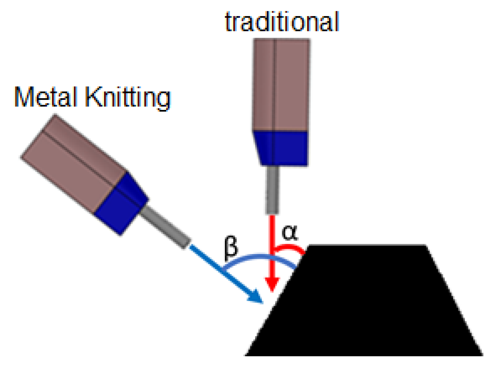
3.2. The Metal Knitting Strategy

The brand-new strategy presented in this work is named Metal Knitting, relating to the movements of needles dealing with yarn to make a woven fabric, which drastically modifies the relative gun/substrate movement from the traditional movements presented in the literature for the CSAM process to date. This new strategy aims to make the CS sprayed particles reach the substrate or the growing CSAM part with an angle that maximizes the DE at the sidewalls, simultaneously controlling the geometry growth of the CSAM part, Figure 7.
For this purpose, the Metal Knitting strategy impresses a circular-like movement on the substrate plane. Still, the CS particles laden jet is not perpendicular to this plane. The final path is a virtual frustum of a cone, with the axis of rotation perpendicular to the substrate plane, as presented schematically in Figure 8. To make clear the Metal Knitting robot movements, the Video S1 is available as a supplementary material to this work.

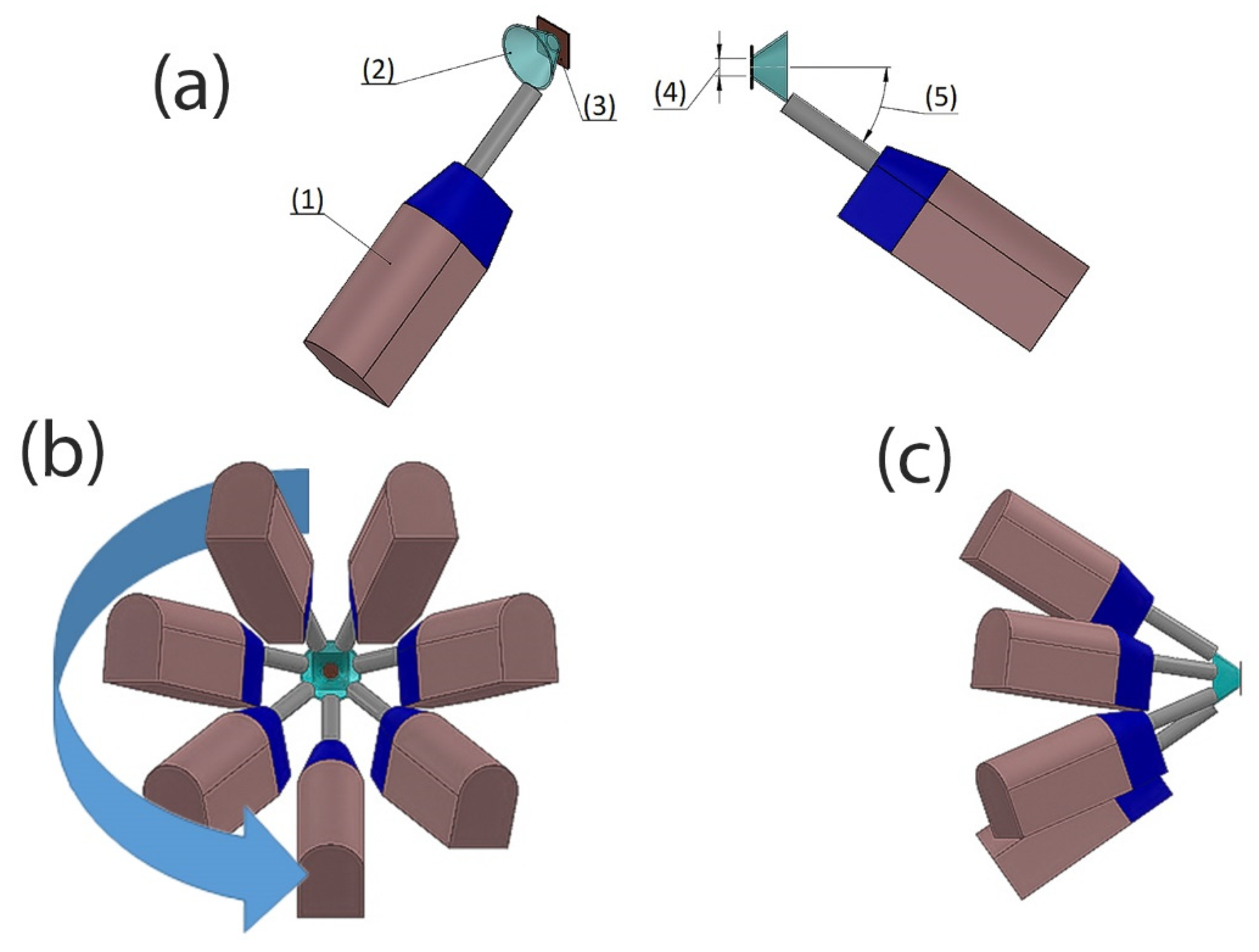
3.2.1. Metal Knitting Parameters

The variables or parameters for Metal Knitting strategy and their influences on the CSAM part characteristics include:
  • Velocity of the robot: the linear or tangential velocity described by the gun in the circular-like trajectory. The higher the velocity, the thinner the CSAM layer;
  • Radius: the distance from the center of the circle to the circumference described by the particles laden jet center on the substrate surface plane, or the small radius of the virtual frustum of the cone path. Excessive radius value generates unevenness in the layer shape;
  • Step: the distance from a circle to an adjacent circle. Excessive step value results in waves-like topography of the layer;
  • Angle: the angle between the axis of rotation and the frustum of the cone generator described by the gun movement. Excessive angle reduces the DE by the powder’s velocity component reaching the substrate.

3.2.2. The Metal Knitting Deposit Properties

A comparison between the CSAM 316L bulks produced by traditional and Metal Knitting strategies is presented in Figure 9, which also shows the real bulk part obtained. Identical deposits were CSAM fabricated with Ti and Ti6Al4V alloy powders with successful results. Visual inspection showed that none of the bulk parts produced (316L, Ti, and Ti6Al4V) presented any cracks or detachments from the substrate. In addition, the parts made by Metal Knitting showed smoother surfaces and more rounded edges compared to the rough finishing and sharp edges seen in the CSAM part produced by the traditional spraying strategy. In this sense, using the Metal Knitting strategy on the substrate’s flat surface, CSAM 316L, Ti, and Ti6Al4V components showed a sidewall angle of around 80 degrees to the substrate surface. It is a significantly smaller inclination value than the inclination produced by the traditional strategy on a flat surface, as shown in Figure 9.
As indicated above, in CS deposition by the traditional strategy, the angle of impact of subsequent particles is always off-normal from the beginning of the process. In contrast, the Metal Knitting strategy can keep this particle impact angle constant throughout the process. As a result, during the cone-like Metal Knitting movement, the CS particles laden jet reaches the substrate with angles that promote higher DE in the side walls. It occurs by improving the velocity vector component normal to the impacting surface, as seen in the scheme presented in Figure 7, which improves the capabilities of the CSAM process to control the final geometry generated.
CSAM parts or any material obtained by CS have properties influenced by the cold-working, resulting from the severe plastic deformation under the material’s recrystallization temperature. This increases the density of dislocations in the metal’s crystalline structure and consequently improves the properties of the sprayed feedstock material. Figure 10 presents the as-sprayed CSAM microstructures obtained by Metal Knitting and traditional strategies, which is in consonance with observations in the literature. There is a trend of higher density for the most ductile sprayed materials, Al and Cu, while harder materials resulted in a higher porosity, as seen for Ti6Al4V. This has influences on the material’s properties, as summarized in Table 4. For the CSAM samples made by the traditional strategy, the microstructures, hardness, and porosity obtained were close to those presented in the literature for 316L [10,13,14,51], Al [21,23,24], Cu [16,17,21,52,53], and Ti alloys [19,20,21]; however, for Metal Knitting the literature did not present any result, because it is a brand-new strategy.
The Metal Knitting materials’ properties must be evaluated by their comparison with the CSAM samples obtained by the traditional strategy. The CSAM Metal Knitting samples showed a higher porosity, but close hardness values. The higher discrepancy in hardness values was seen for the materials more susceptible to cold-working strain hardening, highlighting Ti and 316L, suggesting a higher deformation of particles for CSAM traditional strategy sprayed samples than for the Metal Knitting ones. On the other hand, Ti6Al4V had very close hardness values for both evaluated strategies, as expected by their similarity in microstructures.
Table 5 summarizes the tensile testing results of Ti6Al4V and 316L CSAM parts produced by Metal Knitting and traditional strategies. The latter had higher strength values because the cohesion of particles was higher, which is correlated with the lower porosity presented in Table 4. After all, the lower porosity infers a higher contact area among the particles of the CSAM consolidated material. Furthermore, the higher hardness also indicates a higher cold working by more severe particle deformation, which affects the material strength.

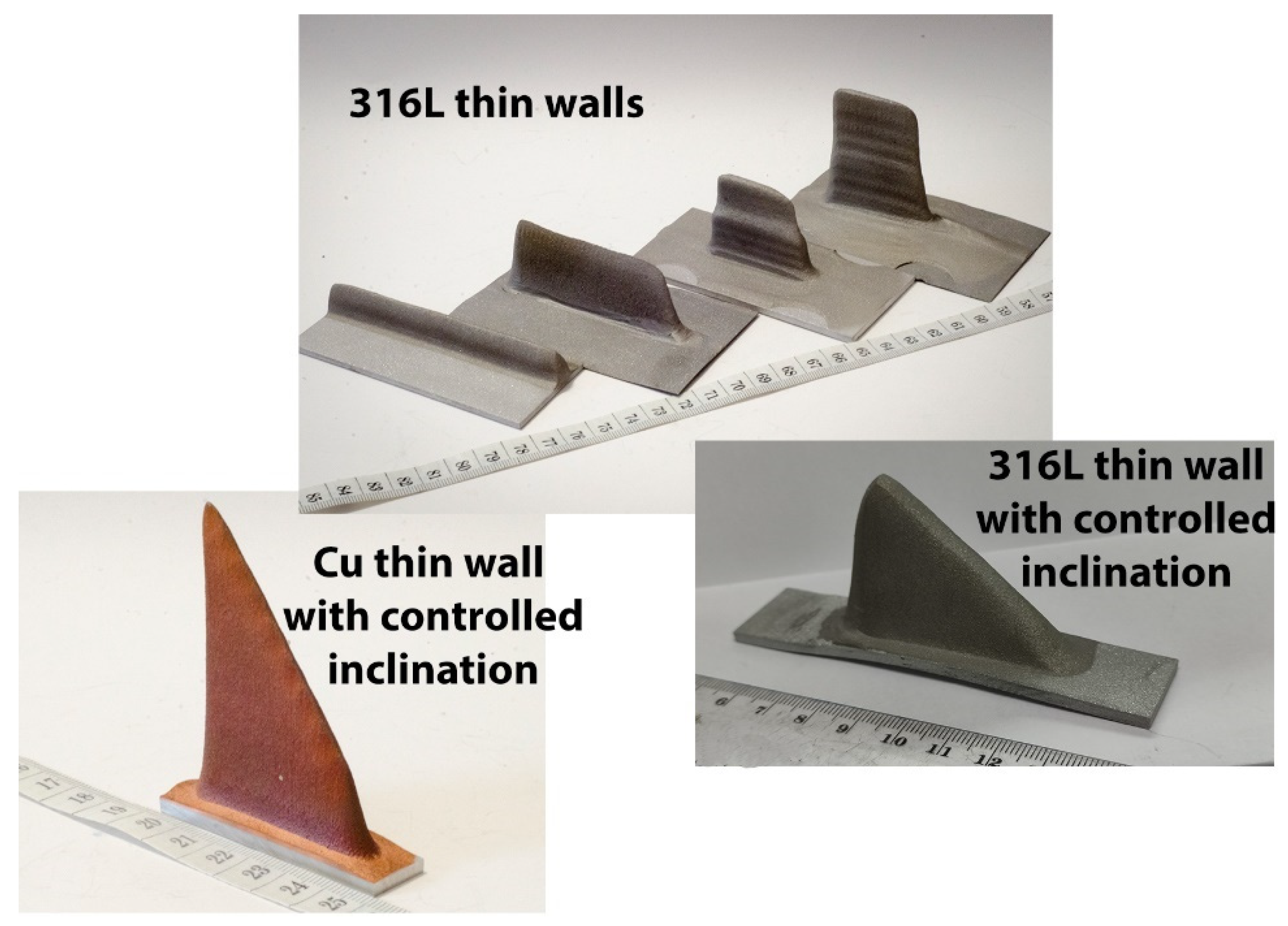
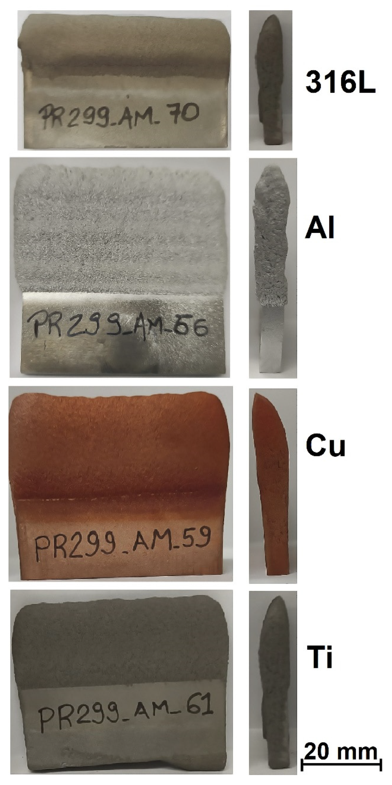
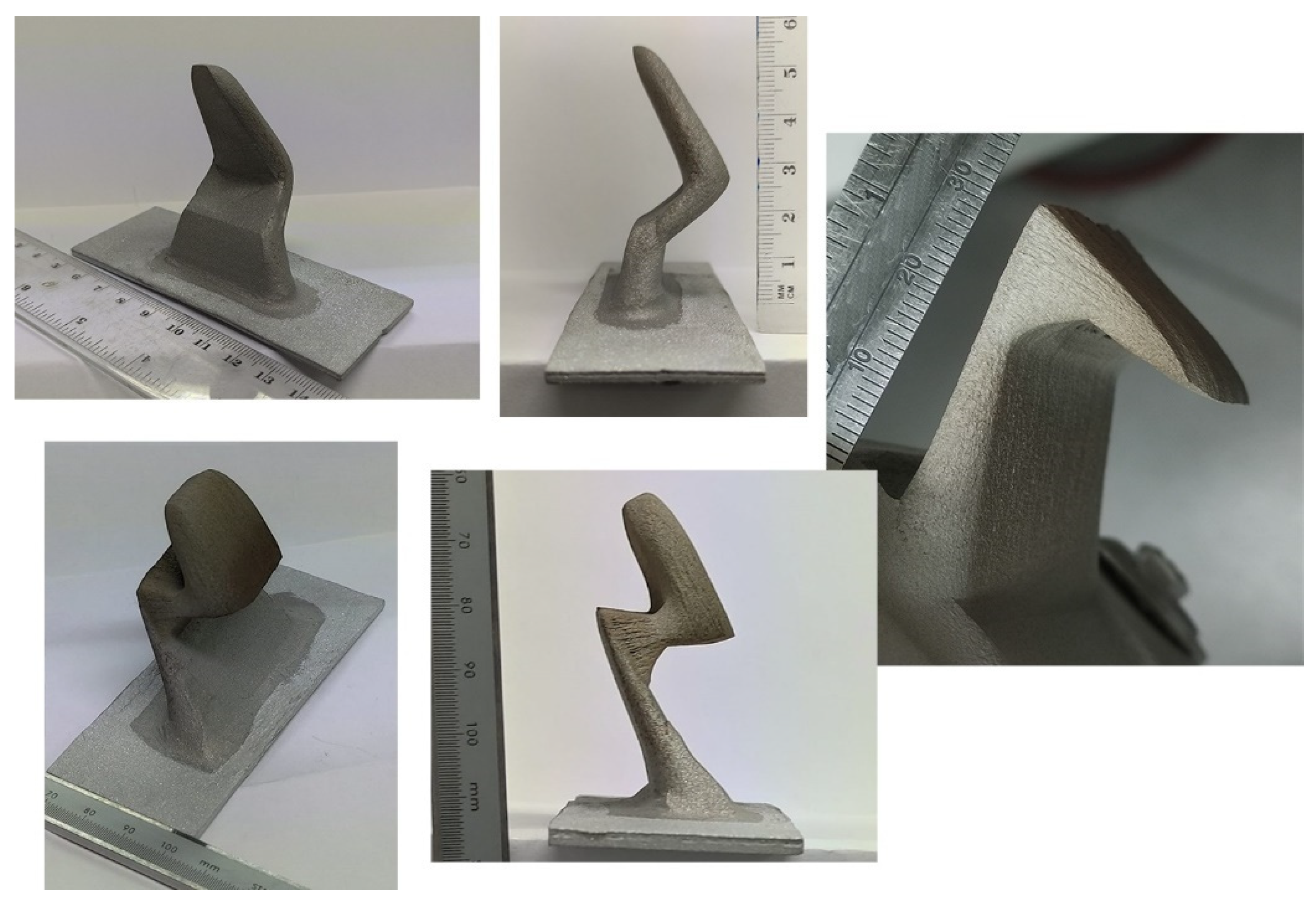
3.2.3. CSAM Geometries Produced by Metal Knitting

In order to show some capacities of this new spraying strategy, complex geometries were produced by CSAM Metal Knitting, which are not feasible by employing the CSAM traditional strategy. Thus, thin straight walls were obtained using the Metal Knitting strategy following one single-line on the substrate’s flat surface, as seen in Figure 11. The geometries presented are not practicable using the traditional strategy because the sidewalls grow with a certain relative inclination, resulting in a pyramid-like shape, while the CSAM sidewalls produced by a single-line Metal Knitting were perpendicular to the substrate surface, as indicated in Table 3.
Adjustments in the Metal Knitting parameters, radius, angle, and standoff distance, promote a variation in CSAM wall thicknesses. This change in the part wall thickness may be made during the part growing, producing an even more complex geometry with steps, like the two right-side 316L samples indicated in Figure 11 (316L thin walls).
Another approach for CSAM Metal Knitting was the variation in the number of steps by layer. The progressive reduction in this quantity of steps made possible the fabrication of a controlled inclined top wall, which is indicated for CSAM Cu and 316L in Figure 11 (Cu with controlled inclination) and Figure 11 (316L with controlled inclination), respectively, resulting in shark dorsal thin like geometries.
Additionally, the Metal Knitting strategy was used on a 50 × 5 mm substrate, a small area for CSAM, and the objective was to grow up the CSAM part with the same 5 mm wall thickness. For this deposition, the substrate and feedstock powder had the same composition, Cu, Ti, Al, and 316L, and a single-line Metal Knitting strategy was selected. The results showed how feasible it was to grow up a part with this 5 mm thick wall by the Metal Knitting strategy, as presented in Figure 12. Varying the Metal Knitting parameters, the 5 mm thick walls produced should be increased to 6 or 7 mm thick to produce sufficient material for a post-machining service.
The Metal Knitting was changed from a straight line based path to a curved lines based path, keeping the cone-like movements; following these non-straight lines, the production of curved walls was feasible, as presented in Figure 13. Different materials were tested, 316L, Ti, and Cu. A change in the robot program made it possible to grow multi-material close walls, Ti and Cu, on the same Al plate substrate.
The same approach presented in Figure 11 for promoting a controlled inclination for straight-line Metal Knitting 316L and Cu is indicated in Figure 13 for a curved path, growing the CSAM part with a controlled inclination. For CSAM 316L, it produced a height of 0 at the beginning of the wall and 16 mm at its end. However, reducing the number of steps per layer, a stairways-like wall was made, as seen in the highest Cu CSAM part in Figure 13. A control in the length of each pass promoted a smooth inclination of the wall, as seen for the 316L curved wall, with height 0 in the beginning of the wall, and 16 mm at its end. However, by decreasing more the length of each pass, a stairways-like top of the wall was made, as seen in the highest Cu CSAM part in Figure 13.
The CSAM Metal Knitting strategy was also evaluated for more complex geometries, which were feasible by controlling the growth direction. Figure 14 presents CSAM 316L parts. For the left and right images of Figure 14, the spraying started in a direction non-perpendicular to the substrate, indicating a good adhesion because no cracks or delamination were observed after visual inspection. The changes in growing angle and direction were performed by the inclination of the substrate holder, making this activity easier because a change in the robot program for each of these geometries would demand much time and effort to make a unique part. However, a robot program can guarantee the dimensional quality requirements for mass production, or at least dozens of components.

4. Conclusions of Using the Metal Knitting CSAM Strategy and Future Perspectives

Comparing the Metal Knitting CSAM strategy to the traditional one, some points may be listed, mainly regarding future advances and possibilities of its use:
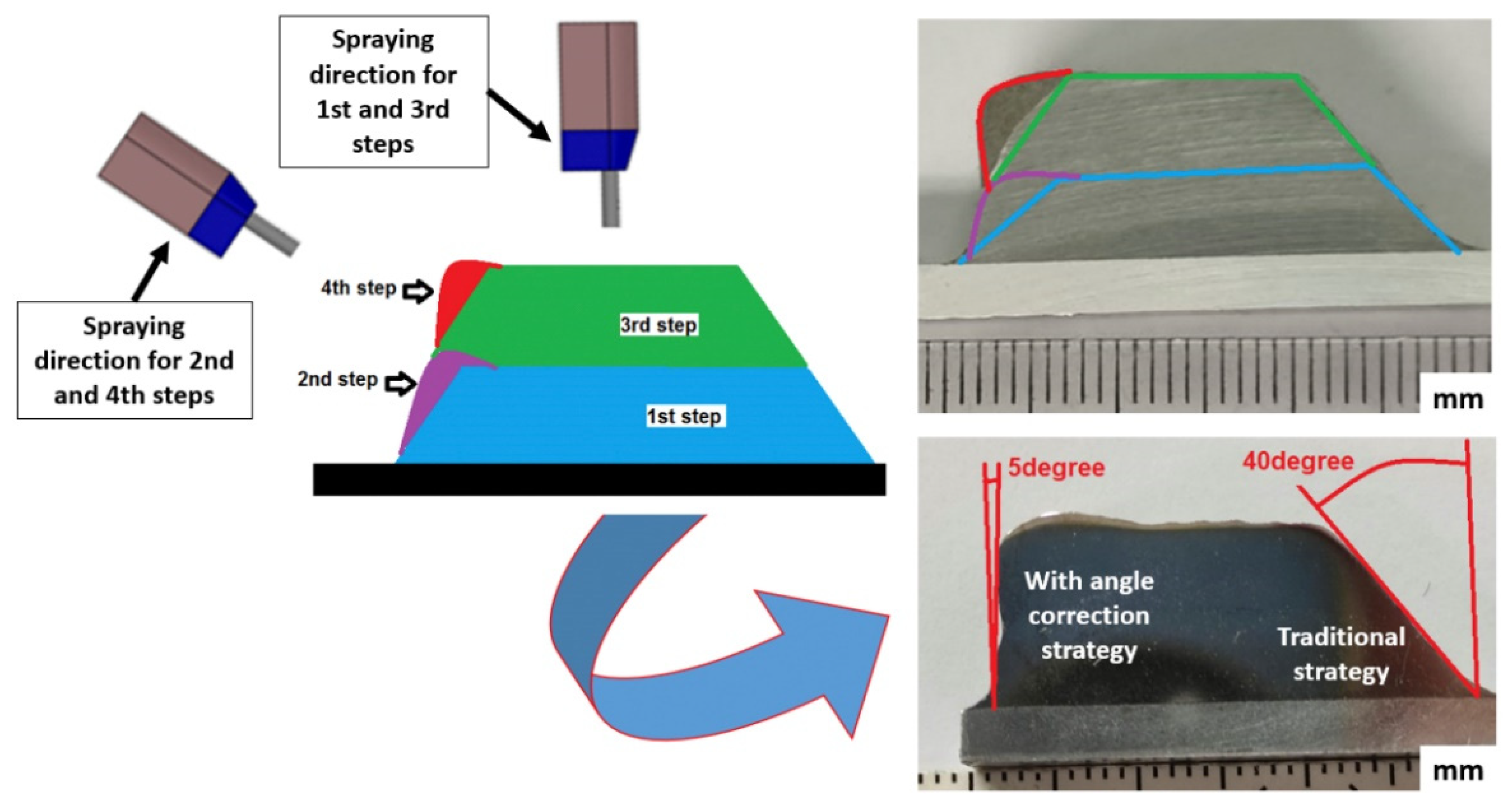
  • Metal Knitting demonstrates the suitability for making geometries and dimensional capacities previously unfeasible by the traditional strategy, obtaining vertical sidewalls, despite 40 degrees of inclination in the 316L CSAM part produced by the traditional strategy;
  • Metal Knitting produces materials with good mechanical properties and similar microstructures to the traditional CSAM strategy. In general, due to the constant cone-like CS gun movement, Metal Knitting results in a lower density than the traditional strategy;
  • Post-processing for densification of Metal Knitting made parts have to be studied, e.g., heat treatments, Hot Isostatic Pressure (HIP), Spark Sintering Plasma (SPS), due to their effectiveness used for parts produced by the traditional CSAM strategy. This qualifies the parts made by Metal Knitting for quality improvement.
  • Metal Knitting strategy is not necessarily a substitute for the traditional one. Still, it can be a complementary stage to this one, redressing the sidewalls to lower angles. Therefore, a combination of robot strategies could be a solution for specific applications, e.g., to build a large bulk, the traditional strategy can be applied for its central area, while knitting is used on the edges. This would prevent the sidewalls inclination and promote the best spraying angle deposition on the central location, which is 90 degrees, typical of the traditional strategy.
  • As a CSAM technique, the Metal Knitting strategy has some challenges, e.g., needing reasonable control of its parameters, distances, and relative’ positions between the substrate and the CS gun, because a misunderstanding in the measurements and positioning may result in an undesired path and consequently unexpected geometry. Moreover, depending on the knitting path and part design, the robot arm does long movements, which might eventually result in a collision between the CS gun and the robot arm. Therefore, to avoid what can be catastrophic for the CS equipment, the robot user must check carefully and slowly the robot trajectory before the CS spraying.
  • Looking for the potential applications of the CSAM metal knitting strategy, one possibility is using it to complement other AM techniques already in use, such as arc-welding or laser processes.
  • In addition, Metal Knitting can be used for repairing elements, such as thin, worn, or damaged walls. Among a wide range of applications and industry sectors, some examples are: repairing Ti alloys turbine compressor blades’ tips, fabrication of superalloys manifolds, production of special prototypes for racing cars, fabrication and repairing of special alloys piping components for the oil and gas industry, repairing of eroded martensitic stainless-steel Kaplan hydraulic runners’ tips, and others.

Supplementary Materials

The following supporting information can be downloaded at: https://www.mdpi.com/article/10.3390/ma15196785/s1, Video S1: CSAM Metal Knitting strategy on flat substrate surface.

Author Contributions

Conceptualization, R.F.V. and J.S.; investigation, R.F.V., V.A.-F. and H.C.; methodology, R.F.V., V.A.-F., J.S., U.O. and Z.G.C.; writing—original draft preparation, R.F.V. and V.A.-F.; writing—review and editing, R.F.V., V.A.-F. and J.S.; funding acquisition, J.S. and I.G.C.; project administration, J.S. and I.G.C.; software, U.O., Z.G.C. and H.C.; supervision, I.G.C. All authors have read and agreed to the published version of the manuscript.

Funding

Grant PID2020-115508RB-C21 funded by MCIN/AEI/10.13039/501100011033 and, as appropriate, by “ERDF A way of making Europe”, by the “European Union” or by the “European Union NextGenerationEU/PRTR”. R.F. Vaz thanks Generalitat de Catalunya for the Ph.D. grant 2020 FISDU 00305. The author V. Albaladejo-Fuentes is a Serra-Hunter Fellow.

Institutional Review Board Statement

Not applicable.

Informed Consent Statement

Not applicable.

Data Availability Statement

The data presented in this study are available on request from the corresponding author.

Acknowledgments

A special thanks to Victor Gómez for his essential work operating the robot and CS equipment. This work would be more difficult without his help.

Conflicts of Interest

The authors declare no conflict of interest.

References

  1. De Souza Corrêa, R.; de Oliveira, U.R.; Abdalla, M.M.; Fernandes, V.A. Systematic Literature Review on Sustainable Products: Impact on Organizations, Research Opportunities and Future Perspectives. Clean. Waste Syst. 2022, 1, 100003. [Google Scholar] [CrossRef]
  2. Jin, Y.; Ji, S.; Li, X.; Yu, J. A Scientometric Review of Hotspots and Emerging Trends in Additive Manufacturing. J. Manuf. Technol. Manag. 2017, 28, 18–38. [Google Scholar] [CrossRef]
  3. Parupelli, S.K.; Desai, S. A Comprehensive Review of Additive Manufacturing (3D Printing): Processes, Applications and Future Potential. Am. J. Appl. Sci. 2019, 16, 244–272. [Google Scholar] [CrossRef]
  4. Savini, A.; Savini, G.G. A Short History of 3D Printing, a Technological Revolution Just Started. In Proceedings of the 2015 ICOHTEC/IEEE International History of High-Technologies and their Socio-Cultural Contexts Conference (HISTELCON), Tel-Aviv, Israel, 18–19 August 2015; pp. 1–8. [Google Scholar]
  5. Yakout, M.; Elbestawi, M.A.; Veldhuis, S.C. A Review of Metal Additive Manufacturing Technologies. Solid State Phenom. 2018, 278, 1–14. [Google Scholar] [CrossRef]
  6. Fang, Z.-C.; Wu, Z.-L.; Huang, C.-G.; Wu, C.-W. Review on Residual Stress in Selective Laser Melting Additive Manufacturing of Alloy Parts. Opt. Laser Technol. 2020, 129, 106283. [Google Scholar] [CrossRef]
  7. Karayel, E.; Bozkurt, Y. Additive Manufacturing Method and Different Welding Applications. J. Mater. Res. Technol. 2020, 9, 11424–11438. [Google Scholar] [CrossRef]
  8. Raoelison, R.N.; Verdy, C.; Liao, H. Cold Gas Dynamic Spray Additive Manufacturing Today: Deposit Possibilities, Technological Solutions and Viable Applications. Mater. Des. 2017, 133, 266–287. [Google Scholar] [CrossRef]
  9. Srikanth, A.; Basha, G.; Venkateshwarlu, B. A Brief Review on Cold Spray Coating Process. Mater. Today Proc. 2019, 22, 1390–1397. [Google Scholar] [CrossRef]
  10. Vaz, R.F.; Silvello, A.; Sanchez, J.; Albaladejo, V.; Cano, I.G. The Influence of the Powder Characteristics on 316L Stainless Steel Coatings Sprayed by Cold Gas Spray. Coatings 2021, 11, 168. [Google Scholar] [CrossRef]
  11. Villa, M.; Dosta, S.; Guilemany, J.M. Optimization of 316L Stainless Steel Coatings on Light Alloys Using Cold Gas Spray. Surf. Coat. Technol. 2013, 235, 220–225. [Google Scholar] [CrossRef]
  12. Yin, S.; Cizek, J.; Yan, X.; Lupoi, R. Annealing Strategies for Enhancing Mechanical Properties of Additively Manufactured 316L Stainless Steel Deposited by Cold Spray. Surf. Coat. Technol. 2019, 370, 353–361. [Google Scholar] [CrossRef]
  13. Bagherifard, S.; Kondas, J.; Monti, S.; Cizek, J.; Perego, F.; Kovarik, O.; Lukac, F.; Gaertner, F.; Guagliano, M. Tailoring Cold Spray Additive Manufacturing of Steel 316 L for Static and Cyclic Load-Bearing Applications. Mater. Des. 2021, 203, 109575. [Google Scholar] [CrossRef]
  14. Dikici, B.; Yilmazer, H.; Ozdemir, I.; Isik, M. The Effect of Post-Heat Treatment on Microstructure of 316L Cold-Sprayed Coatings and Their Corrosion Performance. J. Therm. Spray Technol. 2016, 25, 704–714. [Google Scholar] [CrossRef]
  15. Guerreiro, B.; Vo, P.; Poirier, D.; Legoux, J.-G.; Zhang, X.; Giallonardo, J.D. Factors Affecting the Ductility of Cold-Sprayed Copper Coatings. J. Therm. Spray Technol. 2020, 29, 630–641. [Google Scholar] [CrossRef]
  16. Wu, H.; Huang, C.; Xie, X.; Liu, S.; Wu, T.; Niendorf, T.; Xie, Y.; Deng, C.; Liu, M.; Liao, H.; et al. Influence of Spray Trajectories on Characteristics of Cold-Sprayed Copper Deposits. Surf. Coat. Technol. 2021, 405, 126703. [Google Scholar] [CrossRef]
  17. Yin, S.; Jenkins, R.; Yan, X.; Lupoi, R. Microstructure and Mechanical Anisotropy of Additively Manufactured Cold Spray Copper Deposits. Mater. Sci. Eng. A 2018, 734, 67–76. [Google Scholar] [CrossRef]
  18. Vilardell, A.M.; Cinca, N.; Barriuso, E.; Frigola, J.; Dosta, S.; Cano, I.G.; Guilemany, J.M. X-Ray Microtomographic Characterization of Highly Rough Titanium Cold Gas Sprayed Coating for Identification of Effective Surfaces for Osseointegration. Microscopy 2019, 68, 413–416. [Google Scholar] [CrossRef]
  19. Vargas-Uscategui, A.; King, P.C.; Yang, S.; Chu, C.; Li, J. Toolpath Planning for Cold Spray Additively Manufactured Titanium Walls and Corners: Effect on Geometry and Porosity. J. Mater. Process. Technol. 2021, 298, 117272. [Google Scholar] [CrossRef]
  20. Lek, J.Y.; Bhowmik, A.; Tan, A.W.-Y.; Sun, W.; Song, X.; Zhai, W.; Buenconsejo, P.J.; Li, F.; Liu, E.; Lam, Y.M.; et al. Understanding the Microstructural Evolution of Cold Sprayed Ti-6Al-4V Coatings on Ti-6Al-4V Substrates. Appl. Surf. Sci. 2018, 459, 492–504. [Google Scholar] [CrossRef]
  21. Suhonen, T.; Varis, T.; Dosta, S.; Torrell, M.; Guilemany, J.M. Residual Stress Development in Cold Sprayed Al, Cu and Ti Coatings. Acta Mater. 2013, 61, 6329–6337. [Google Scholar] [CrossRef]
  22. Bobzin, K.; Wietheger, W.; Knoch, M.A.; Schacht, A.; Reisgen, U.; Sharma, R.; Oster, L. Comparison of Residual Stress Measurements Conducted by X-ray Stress Analysis and Incremental Hole Drilling Method. J. Therm. Spray Technol. 2020, 29, 1218–1228. [Google Scholar] [CrossRef]
  23. Rech, S.; Trentin, A.; Vezzù, S.; Vedelago, E.; Legoux, J.G.; Irissou, E. Different Cold Spray Deposition Strategies: Single- and Multi-Layers to Repair Aluminium Alloy Components. J. Therm. Spray Technol. 2014, 23, 1237–1250. [Google Scholar] [CrossRef]
  24. Fan, N.; Cizek, J.; Huang, C.; Xie, X.; Chlup, Z.; Jenkins, R.; Lupoi, R.; Yin, S. A New Strategy for Strengthening Additively Manufactured Cold Spray Deposits through in-Process Densification. Addit. Manuf. 2020, 36, 101626. [Google Scholar] [CrossRef]
  25. Silvello, A.; Cavaliere, P.; Rizzo, A.; Valerini, D.; Dosta Parras, S.; Garcia Cano, I. Fatigue Bending Behavior of Cold-Sprayed Nickel-Based Superalloy Coatings. J. Therm. Spray Technol. 2019, 28, 930–938. [Google Scholar] [CrossRef]
  26. Vaßen, R.; Fiebig, J.; Kalfhaus, T.; Gibmeier, J.; Kostka, A.; Schrüfer, S. Correlation of Microstructure and Properties of Cold Gas Sprayed INCONEL 718 Coatings. J. Therm. Spray Technol. 2020, 29, 1455–1465. [Google Scholar] [CrossRef]
  27. Yan, X.; Huang, C.; Chen, C.; Bolot, R.; Dembinski, L.; Huang, R.; Ma, W.; Liao, H.; Liu, M. Additive Manufacturing of WC Reinforced Maraging Steel 300 Composites by Cold Spraying and Selective Laser Melting. Surf. Coat. Technol. 2019, 371, 161–171. [Google Scholar] [CrossRef]
  28. Chen, C.; Yan, X.; Xie, Y.; Huang, R.; Kuang, M.; Ma, W.; Zhao, R.; Wang, J.; Liu, M.; Ren, Z.; et al. Microstructure Evolution and Mechanical Properties of Maraging Steel 300 Fabricated by Cold Spraying. Mater. Sci. Eng. A 2019, 743, 482–493. [Google Scholar] [CrossRef]
  29. Vaz, R.F.; Silvello, A.; Albaladejo, V.; Sanchez, J.; Cano, I.G. Improving the Wear and Corrosion Resistance of Maraging Part Obtained by Cold Gas Spray Additive m Anufacturing. Metals 2021, 11, 1092. [Google Scholar] [CrossRef]
  30. Yin, S.; Cavaliere, P.; Aldwell, B.; Jenkins, R.; Liao, H.; Li, W.; Lupoi, R. Cold Spray Additive Manufacturing and Repair: Fundamentals and Applications. Addit. Manuf. 2018, 21, 628–650. [Google Scholar] [CrossRef]
  31. Prashar, G.; Vasudev, H. A Comprehensive Review on Sustainable Cold Spray Additive Manufacturing: State of the Art, Challenges and Future Challenges. J. Clean. Prod. 2021, 310, 127606. [Google Scholar] [CrossRef]
  32. Wu, H.; Xie, X.; Liu, M.; Verdy, C.; Zhang, Y.; Liao, H.; Deng, S. Stable Layer-Building Strategy to Enhance Cold-Spray-Based Additive Manufacturing. Addit. Manuf. 2020, 35, 101356. [Google Scholar] [CrossRef]
  33. Pattison, J.; Celotto, S.; Morgan, R.; Bray, M.; O’Neill, W. Cold Gas Dynamic Manufacturing: A Non-Thermal Approach to Freeform Fabrication. Int. J. Mach. Tools Manuf. 2007, 47, 627–634. [Google Scholar] [CrossRef]
  34. Nardi, A.T.; El-Wardany, T.I.; Viens, D.V.; Lynch, M.E.; Hsu, A.; Klecka, M.A.; Gu, W. Additive Topology Optimized Manufacturing for Multi-Functional Components. US20140277669A1, 18 September 2014. [Google Scholar]
  35. Prasad, K.; Khalik, M.A.; Hutasoit, N.; Rahman Rashid, R.A.; Rashid, R.; Duguid, A.; Palanisamy, S. Printability of Low-Cost Pre-Heat-Treated Ball Milled Al7075 Powders Using Compressed Air Assisted Cold Spray Additive Manufacturing. Addit. Manuf. Lett. 2022, 3, 100046. [Google Scholar] [CrossRef]
  36. Silvello, A.; Cavaliere, P.D.; Albaladejo, V.; Martos, A.; Dosta, S.; Cano, I.G. Powder Properties and Processing Conditions Affecting Cold Spray Deposition. Coatings 2020, 10, 91. [Google Scholar] [CrossRef]
  37. Gilmore, D.L.; Dykhuizen, R.C.; Neiser, R.A.; Roemer, T.J.; Smith, M.F. Particle Velocity and Deposition Efficiency in the Cold Spray Process. J. Therm. Spray Technol. 1999, 8, 576–582. [Google Scholar] [CrossRef]
  38. Li, C.-J.; Li, W.-Y.; Wang, Y.-Y. Effect of Spray Angle on Deposition Characteristics in Cold Spraying. In Thermal Spray 2003: Advancing the Science & Applying the Technology; Moreau, C., Marple, B.R., Eds.; ASM International: Orlando, FL, USA, 2003; pp. 91–96. [Google Scholar]
  39. Wu, H.; Xie, X.; Liu, M.; Chen, C.; Liao, H.; Zhang, Y.; Deng, S. A New Approach to Simulate Coating Thickness in Cold Spray. Surf. Coat. Technol. 2020, 382, 1–14. [Google Scholar] [CrossRef]
  40. Wu, H.; Raoelison, R.N.; Zhang, Y.; Deng, S.; Liao, H. Cold Spraying of 3D Parts—Challenges. In Thermal Spray Coatings; Thakur, L., Vasudev, H., Eds.; CRC Press: Boca Raton, FL, USA, 2021; pp. 37–58. [Google Scholar]
  41. Matts, O.; Hammoud, H.; Sova, A.; Bensaid, Z.; Kermouche, G.; Klöcker, H.; Bosch, C.; Texier-Mandoki, N. Influence of Cold Spray Nozzle Displacement Strategy on Microstructure and Mechanical Properties of Cu/SiC Composites Coating. Key Eng. Mater. 2019, 813, 110–115. [Google Scholar] [CrossRef]
  42. Bae, G.; Kumar, S.; Yoon, S.; Kang, K.; Na, H.; Kim, H.; Lee, C. Bonding Features and Associated Mechanisms in Kinetic Sprayed Titanium Coatings. Acta Mater. 2009, 57, 5654–5666. [Google Scholar] [CrossRef]
  43. Ichikawa, Y.; Tokoro, R.; Tanno, M.; Ogawa, K. Elucidation of Cold-Spray Deposition Mechanism by Auger Electron Spectroscopic Evaluation of Bonding Interface Oxide Film. Acta Mater. 2019, 164, 39–49. [Google Scholar] [CrossRef]
  44. Sun, W.; Tan, A.W.Y.; Marinescu, I.; Toh, W.Q.; Liu, E. Adhesion, Tribological and Corrosion Properties of Cold-Sprayed CoCrMo and Ti6Al4V Coatings on 6061-T651 Al Alloy. Surf. Coat. Technol. 2017, 326, 291–298. [Google Scholar] [CrossRef]
  45. Faizan-Ur-Rab, M.; Zahiri, S.H.; Masood, S.H.; Phan, T.D.; Jahedi, M.; Nagarajah, R. Application of a Holistic 3D Model to Estimate State of Cold Spray Titanium Particles. Mater. Des. 2016, 89, 1227–1241. [Google Scholar] [CrossRef]
  46. Zahiri, S.H.; Yang, W.; Jahedi, M. Characterization of Cold Spray Titanium Supersonic Jet. J. Therm. Spray Technol. 2009, 18, 110–117. [Google Scholar] [CrossRef]
  47. Champagne, V.K.; Helfritch, D.J.; Dinavahi, S.P.G.; Leyman, P.F. Theoretical and Experimental Particle Velocity in Cold Spray. J. Therm. Spray Technol. 2011, 20, 425–431. [Google Scholar] [CrossRef]
  48. Kotoban, D.; Grigoriev, S.; Okunkova, A.; Sova, A. Influence of a Shape of Single Track on Deposition Efficiency of 316L Stainless Steel Powder in Cold Spray. Surf. Coat. Technol. 2017, 309, 951–958. [Google Scholar] [CrossRef]
  49. Rokni, M.R.; Nutt, S.R.; Widener, C.A.; Champagne, V.K.; Hrabe, R.H. Review of Relationship Between Particle Deformation, Coating Microstructure, and Properties in High-Pressure Cold Spray. J. Therm. Spray Technol. 2017, 26, 1308–1355. [Google Scholar] [CrossRef]
  50. Lynch, M.E.; Gu, W.; El-Wardany, T.; Hsu, A.; Viens, D.; Nardi, A.; Klecka, M. Design and Topology/Shape Structural Optimisation for Additively Manufactured Cold Sprayed Components. Virtual Phys. Prototyp. 2013, 8, 213–231. [Google Scholar] [CrossRef]
  51. Tavares, S.S.M.; Rodrigues, C.R.; Pardal, J.M.; da Silva Barbosa, E.; de Abreu, H.F.G. Effects of Post Weld Heat Treatments on the Microstructure and Mechanical Properties of Dissimilar Weld of Supermartensític Stainless Steel. Mater. Res. 2014, 17, 1336–1343. [Google Scholar] [CrossRef]
  52. Yang, K.; Li, W.; Yang, X.; Xu, Y. Anisotropic Response of Cold Sprayed Copper Deposits. Surf. Coat. Technol. 2018, 335, 219–227. [Google Scholar] [CrossRef]
  53. Eason, P.D.; Fewkes, J.A.; Kennett, S.C.; Eden, T.J.; Tello, K.; Kaufman, M.J.; Tiryakioğlu, M. On the Characterization of Bulk Copper Produced by Cold Gas Dynamic Spray Processing in as Fabricated and Annealed Conditions. Mater. Sci. Eng. A 2011, 528, 8174–8178. [Google Scholar] [CrossRef]
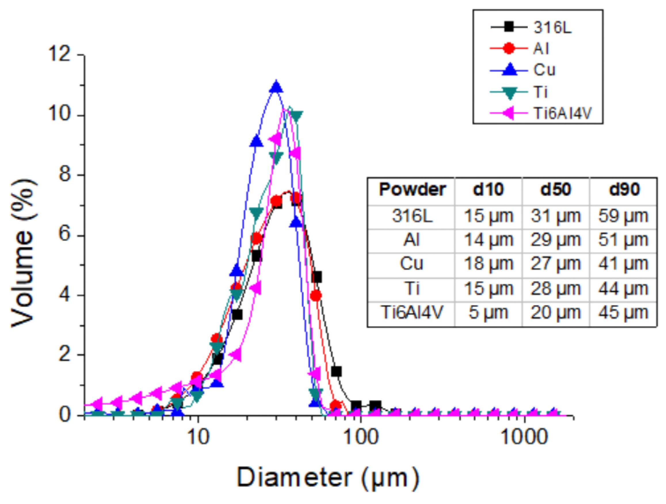
Figure 1. Strategies of robot path for CSAM, (a) traditional or bidirectional and (b) cross-hatching.
Materials 15 06785 g001
Figure 2. Scheme of strategy to compensate the sidewall inclination. The CSAM part cross-section is 316L on Al substrate.
Materials 15 06785 g002
Figure 3. SEM images of feedstock powders for CSAM.
Materials 15 06785 g003
Figure 4. Feedstock particle size distribution for CSAM.
Materials 15 06785 g004
Figure 5. CSAM 316L growing from a substrate’s flat surface or from its edge.
Materials 15 06785 g005
Figure 6. Scheme of CS particles laden jet. (1) Nozzle, (2) sparse particles and lower velocity particles laden jet, (3) concentrated particles and high-velocity particles laden jet, (4) sprayed material, (5) flat substrate.
Materials 15 06785 g006
Figure 7. Scheme of the angle of impact of particles on an inclined surface by traditional (α) and Metal Knitting (β) strategies.
Materials 15 06785 g007
Figure 8. Metal Knitting strategy scheme. (a) (1) CS gun, (2) virtual frustum of cone path, (3) substrate, (4) radius, (5) angle. (b,c) simulation of different directions of view of CS gun describing the Metal Knitting movements.
Materials 15 06785 g008
Figure 9. CSAM 316L bulks. (a) traditional strategy on the substrate edges and (b) Metal Knitting strategy on flat substrate. (c) scheme comparing the geometries obtained.
Materials 15 06785 g009
Figure 10. CSAM microstructures.
Materials 15 06785 g010
Figure 11. CSAM straight thin wall parts made by Metal Knitting strategy on flat substrate.
Materials 15 06785 g011
Figure 12. CSAM part on narrow substrate surface made by Metal Knitting strategy.
Materials 15 06785 g012
Figure 13. CSAM curved parts made by the Metal Knitting strategy.
Materials 15 06785 g013
Figure 14. CSAM 316L complex geometries made by the Metal Knitting strategy.
Materials 15 06785 g014
Table 1. Feedstock powders chemical composition (wt.%).
PowderCrNiMoMnSiFeCuTiAlV
316L16122.50.5<0.1Bal.
Cu 100
Ti 100
Ti6Al4V Bal.5.93.9
Al 100
Table 2. CS spraying parameters.
PowderN2 Temperature [°C]N2 Pressure [MPa]Standoff Distance [mm]
316L10006.025
Cu7003.025
Ti9006.425
Ti6Al4V10006.525
Al4503.025
Table 3. Sidewall angles produced by traditional and Metal Knitting strategies.
MaterialSidewall Angle Relative to a Line Normal to the Substrate [Degree]
on Substrate’s Flat Surfaceon Substrate’s Edge
Metal Knitting StrategyTraditional StrategyMetal Knitting StrategyTraditional Strategy
316L860020
Al04505
Cu075025
Ti104500
Ti6Al4V104005
Table 4. CSAM material properties produced by traditional and Metal Knitting strategies.
MaterialStrategyHardness [HV0.3]Porosity [%]
316LMetal Knitting246 ± 338
Traditional374 ± 264
AlMetal Knitting50 ± 321
Traditional49 ± 83
CuMetal Knitting88 ± 107
Traditional109 ± 123
TiMetal Knitting199 ± 2210
Traditional262 ± 437
Ti6Al4VMetal Knitting229 ± 3128
Traditional236 ± 3214
Table 5. CSAM produced by traditional and Metal Knitting UTS results.
MaterialStrategyUTS [MPa]
316LMetal Knitting61 ± 2
Traditional184 ± 9
Ti6Al4VMetal Knitting32 ± 12
Traditional121 ± 25
Publisher’s Note: MDPI stays neutral with regard to jurisdictional claims in published maps and institutional affiliations.

