
Investigation of the Tribological Behavior and Microstructure of Plasma-Cladded Fe–Cr–Mo–Ni–B Coating

Abstract
:1. Introduction
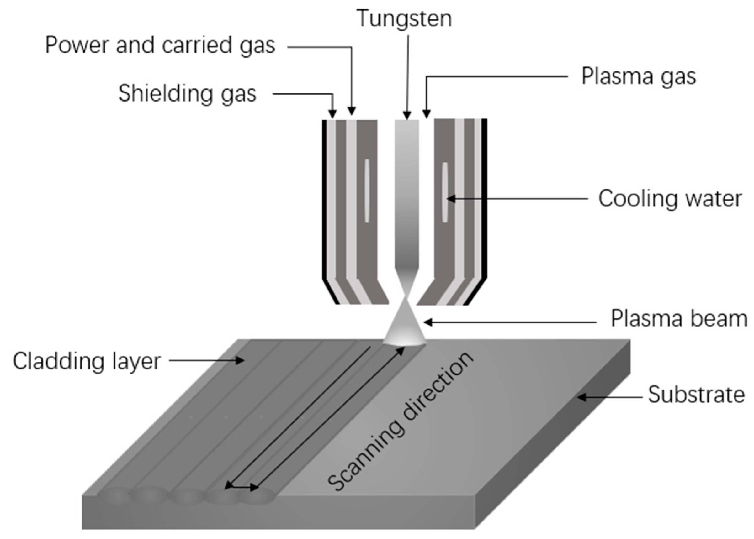
2. Materials and Methods
3. Results and Discussion
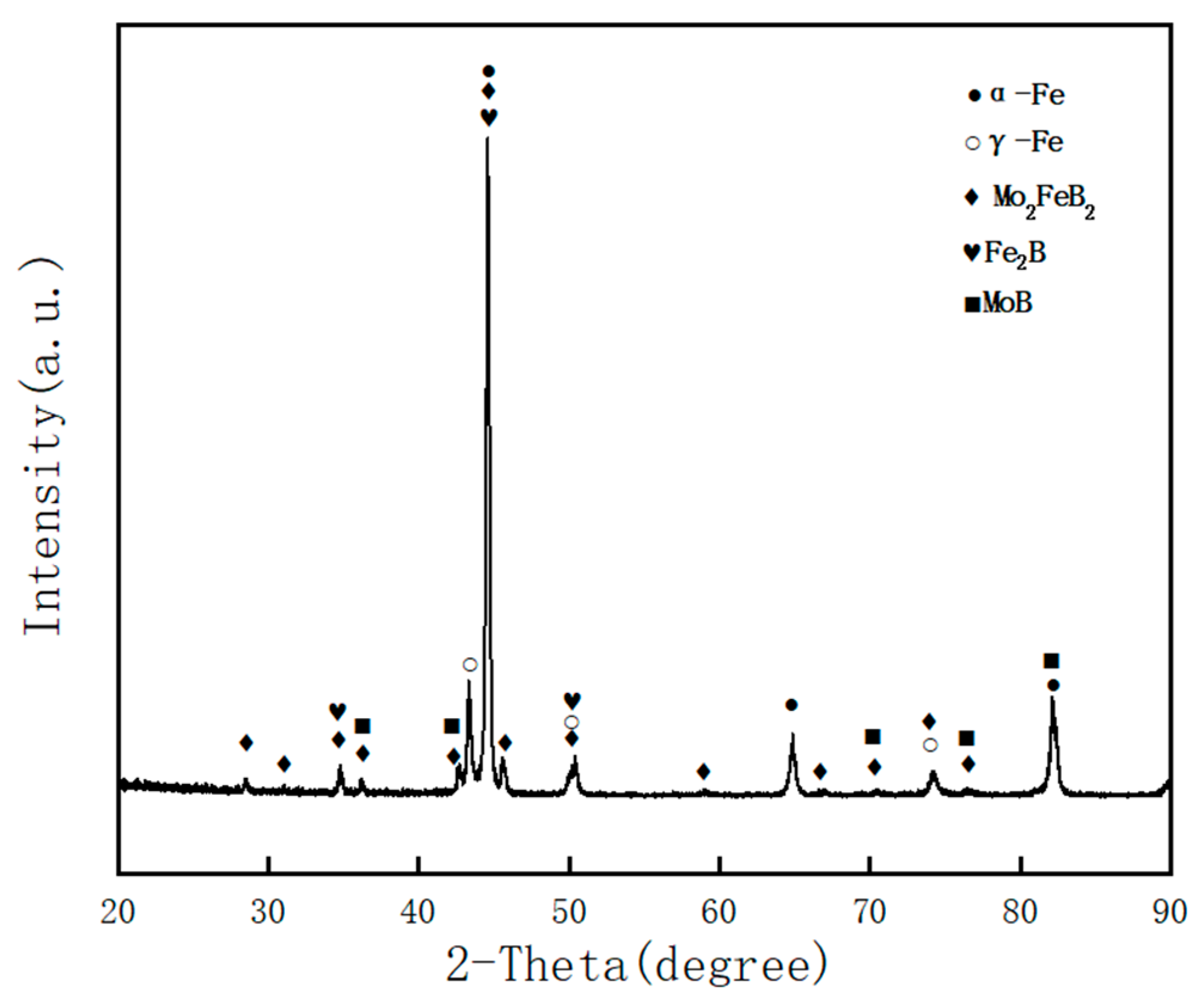
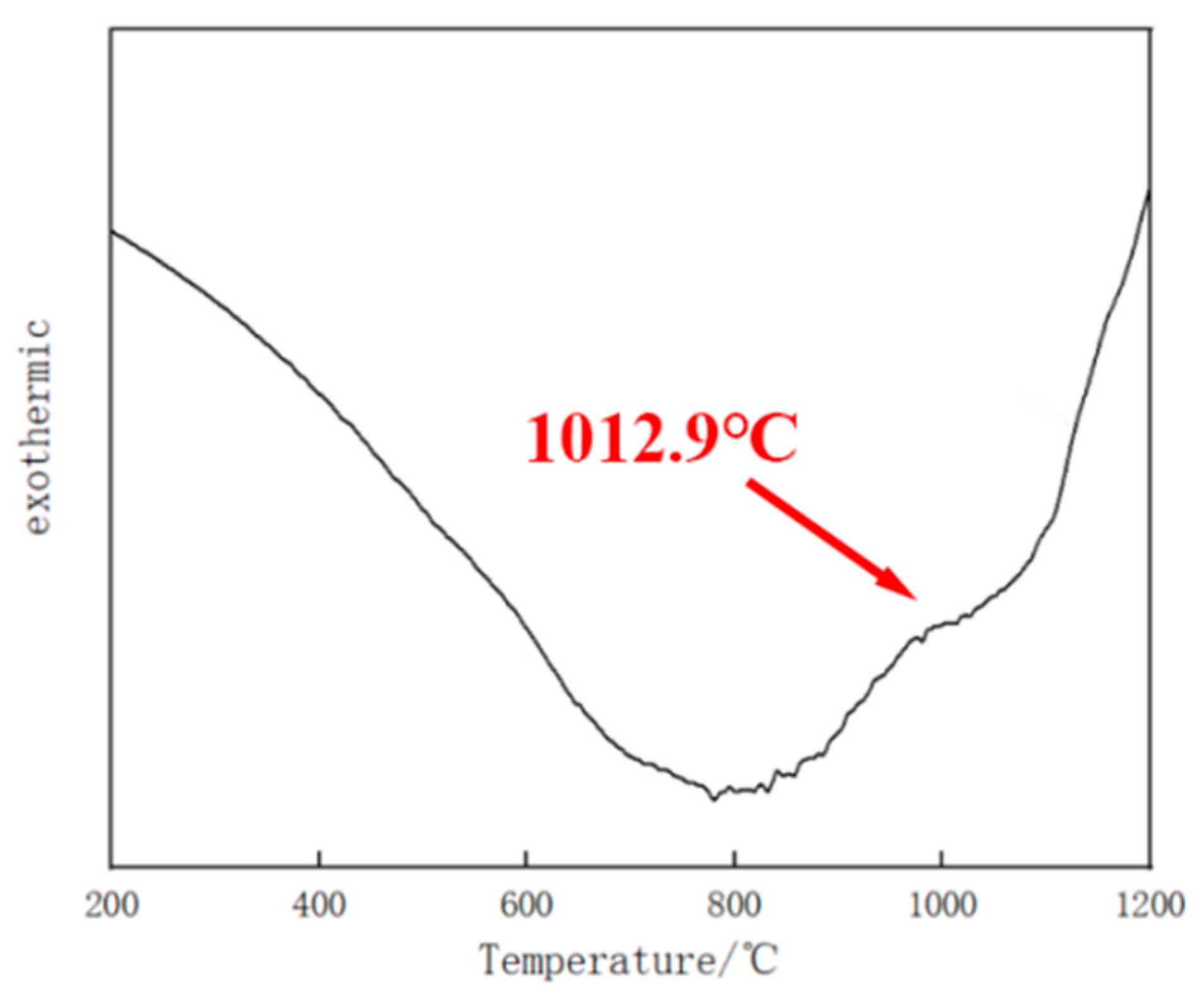
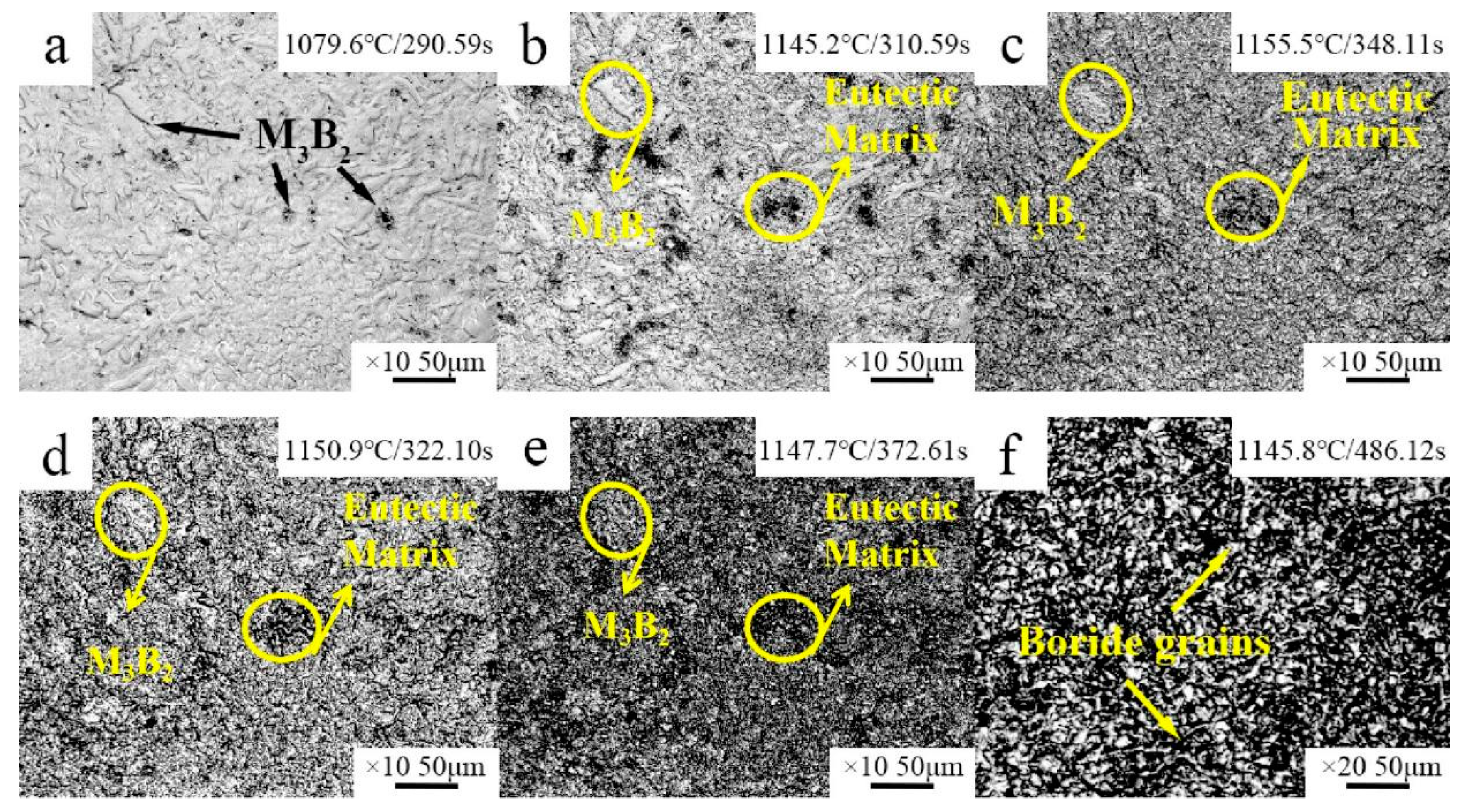
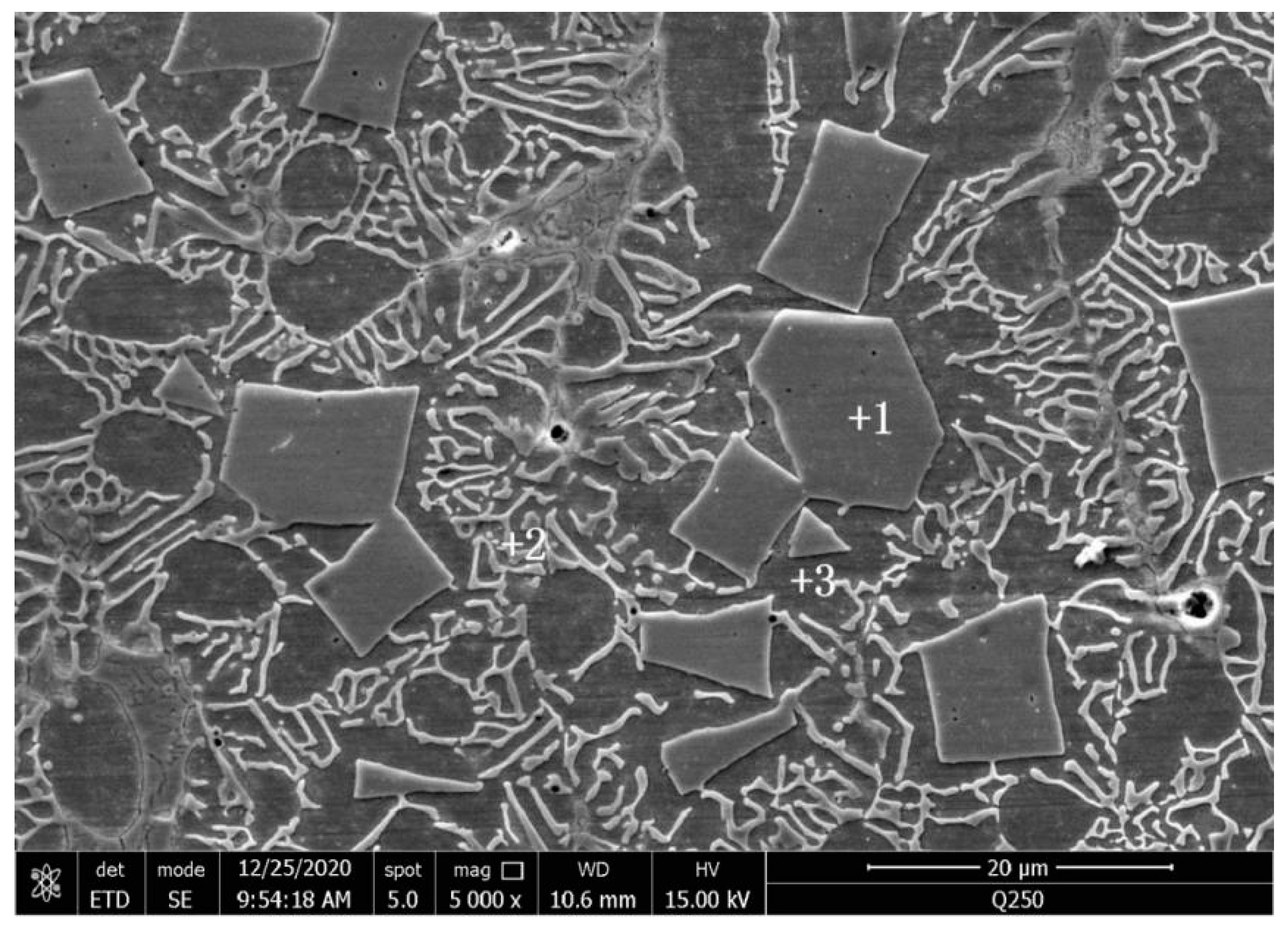
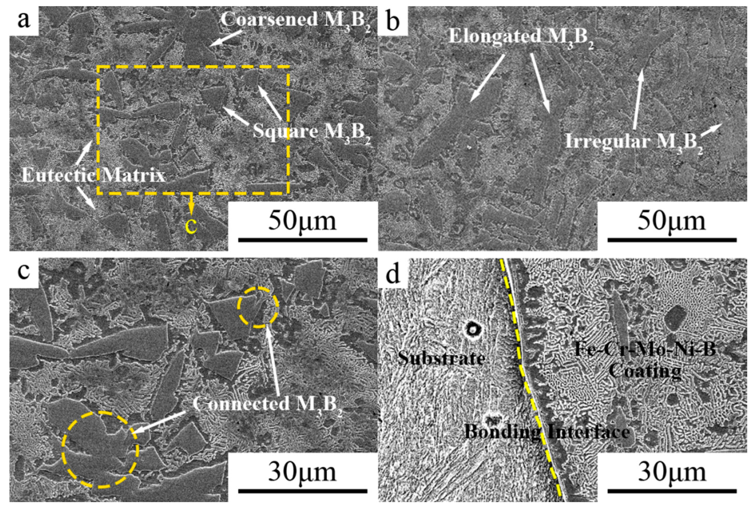
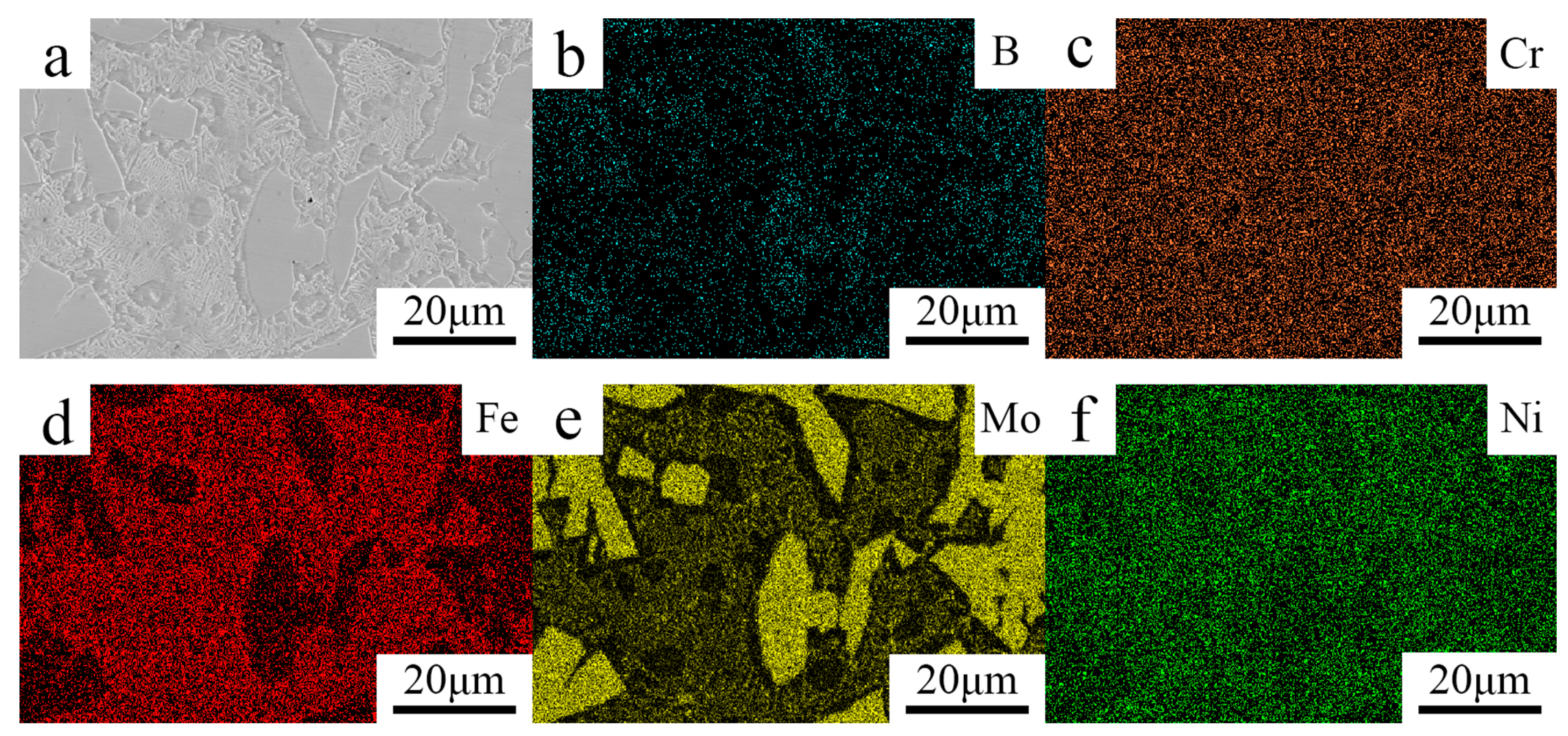
3.1. Microstructure
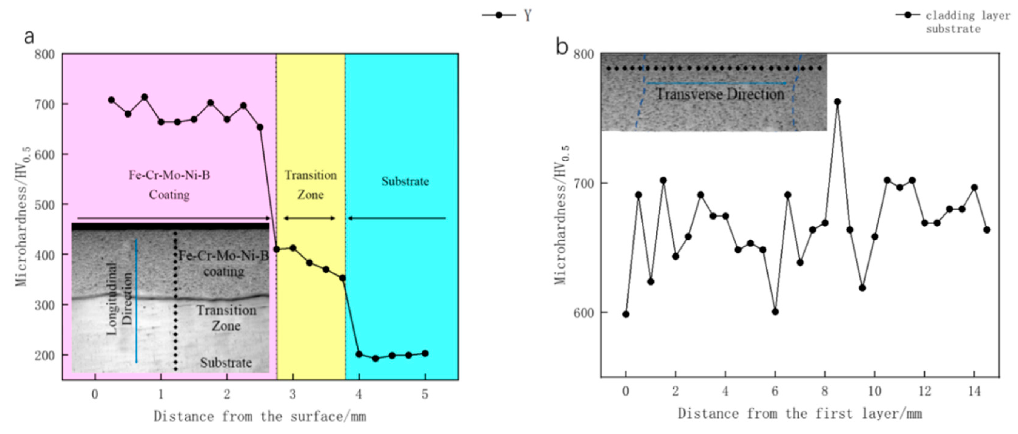
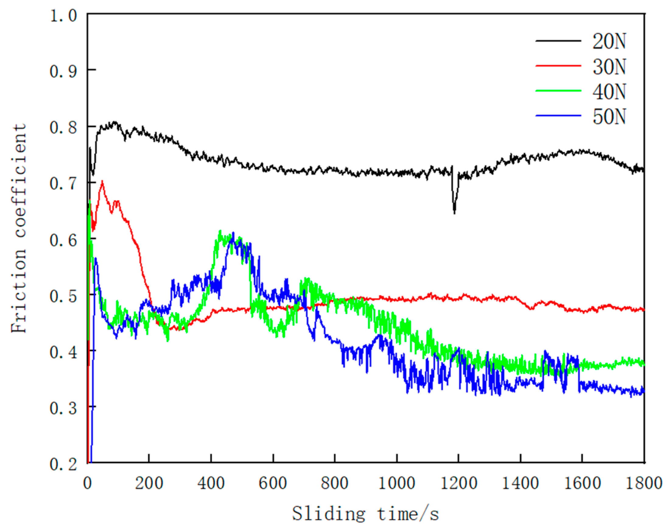
3.2. Vickers Hardness and Tribological Properties
4. Conclusions
- (1)
- The Fe–Cr–Mo–Ni–B coating was prepared by plasma cladding technology. The Mo2FeB2 hard phase connects with other phases and grows to a different morphology.
- (2)
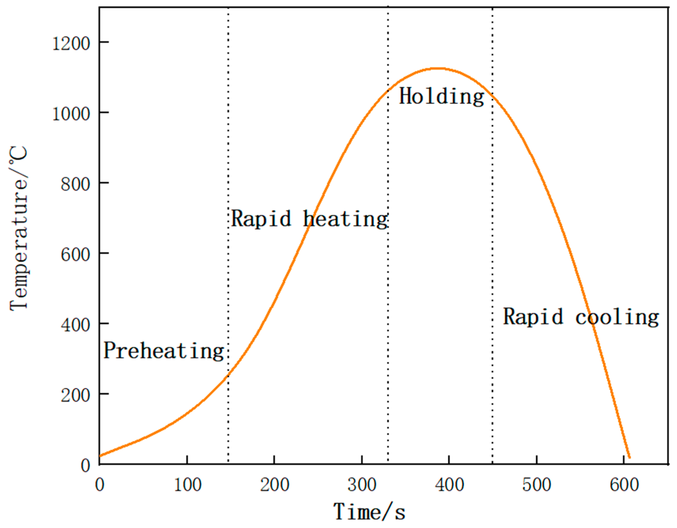
- The microstructure of the Fe–Cr–Mo–Ni–B coating remains stable when the temperature is below 1050 °C. The Mo2FeB2 phase has good thermodynamic stability and stably exists in the high-temperature liquid phase. The growth and coalescence process of the eutectic matrix and Mo2FeB2 grains could occur at about 1150 °C.
- (3)
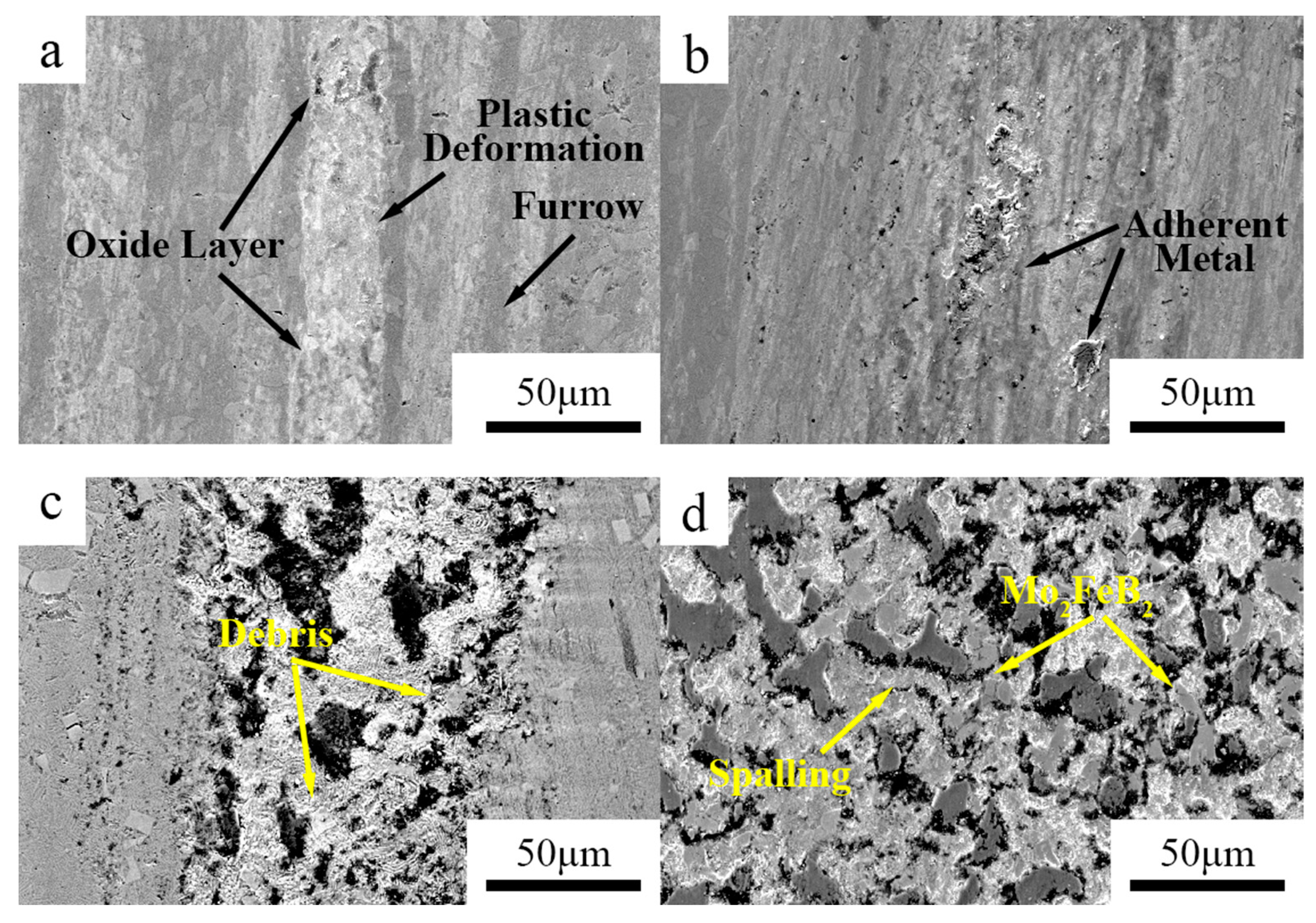
- The hardness value of the Fe–Cr–Mo–Ni–B coating was much higher than that of the base metal. The wear mechanisms of the Fe–Cr–Mo–Ni–B coating under dry sliding were primarily caused by adhesive wear, accompanying abrasive wear and oxidation wear, and the Mo2FeB2 phase plays an important role in the wear-resistance property.
Author Contributions
Funding
Institutional Review Board Statement
Informed Consent Statement
Data Availability Statement
Conflicts of Interest
References
- Wan, M.Q.; Shi, J.; Lei, L.; Cui, Z.Y.; Wang, H.L.; Wang, X. A comparative study of the microstructure, mechanical properties and corrosion resistance of Ni- or Fe- based composite coatings by laser cladding. J. Mater. Eng. Perform. 2018, 27, 2844–2854. [Google Scholar] [CrossRef]
- Peng, Y.B.; Zhang, W.; Li, T.C.; Zhang, M.Y.; Wang, L.; Song, Y.; Hu, S.H.; Hu, Y. Microstructures and mechanical properties of FeCoCrNi high entropy alloy/WC reinforcing particles composite coatings prepared by laser cladding and plasma cladding. Int. J. Refract. Met. Hard Mater. 2019, 84, 105044. [Google Scholar] [CrossRef]
- Pawar, S.; Mukhopadhyay, G. Metallurgical and tribological evaluation of Fe-Cr-C hardfacing alloys. J. Fail. Anal. Prev. 2018, 18, 868–876. [Google Scholar] [CrossRef]
- Yuan, Y.; Li, Z.G. Microstructure and tribology behaviors of in-situ WC/Fe carbide coating fabricated by plasma transferred arc metallurgic reaction. Appl. Surf. Sci. 2017, 423, 13–24. [Google Scholar] [CrossRef]
- Cui, G.J.; Wei, J.; Wu, G.X. Wear behavior of Fe-Cr-B alloys under dry sliding condition. Ind. Lubr. Tribol. 2015, 67, 336–343. [Google Scholar] [CrossRef]
- Zhuang, M.H.; Li, M.Q.; Wang, J.; Ma, Z.; Yuan, S.D. Study on composition, microstructure and wear behavior of Fe-B-C wear-resistant surfacing alloys. J. Mater. Eng. Perform. 2017, 26, 6182–6192. [Google Scholar] [CrossRef]
- Ma, S.Q.; Xing, J.D.; Liu, G.F.; Yi, D.W.; Fu, H.G.; Zhang, J.J.; Li, Y.F. Effect of chromium concentration on microstructure and properties of Fe-3.5B alloy. Mater. Sci. Eng. A 2010, 527, 6800–6808. [Google Scholar] [CrossRef]
- Tian, Y.; Ju, J.; Fu, H.G.; Ma, S.Q.; Lin, J.; Lei, Y.P. Effect of chromium content on microstructure, hardness, and wear resistance of as-cast Fe-Cr-B alloy. J. Mater. Eng. Perform. 2019, 28, 6428–6437. [Google Scholar] [CrossRef]
- Ni, X.J.; Wang, S.Z.; Zhao, Y.T.; Li, W.G.; Jiao, X. Investigation on microstructure, hardness, and corrosion resistance of Mo-Ni-B coatings prepared by laser cladding technique. Coatings 2019, 9, 856. [Google Scholar] [CrossRef]
- Yu, H.Z.; Zheng, Y.; Liu, W.J.; Zheng, J.Z.; Xiong, W.H. Effect of V content on the microstructure and mechanical properties of Mo2FeB2 based cermets. Mater. Des. 2010, 31, 2680–2683. [Google Scholar] [CrossRef]
- Zhang, J.J.; Zheng, Y.; Chen, J.X.; Zhou, W.; Zhao, Y.J.; Feng, P. Microstructures and mechanical properties of Mo2FeB2-based cermets prepared by two-step sintering technique. Int. J. Refract. Met. Hard Mater. 2018, 72, 56–62. [Google Scholar] [CrossRef]
- Yang, F.H.; Su, B.; Zhang, A.J.; Meng, J.H.; Han, J.S.; Wu, Y.Z. Tribological properties and wear mechanisms of Mo2FeB2 based cermets at high temperatures. Tribol. Int. 2018, 120, 391–397. [Google Scholar] [CrossRef]
- Yu, H.Z.; Liu, W.J.; Zheng, Y. Effect of carbon content on the microstructure and mechanical properties of Mo2FeB2 based cermets. Int. J. Refract. Met. Hard Mater. 2011, 29, 724–728. [Google Scholar] [CrossRef]
- Yu, H.Z.; Zheng, Y.; Liu, W.J.; Pang, X.M.; Zheng, J.Z.; Xiong, W.H. Effect of Mo/B atomic ratio on the microstructure and mechanical properties of Mo2FeB2 based cermets. Int. J. Refract. Met. Hard Mater. 2010, 28, 338–342. [Google Scholar] [CrossRef]
- Ren, X.H.; Yu, L.M.; Liu, Y.C.; Li, H.J.; Wu, J.F.; Liu, Z.H. Effects of extra boron addition on the liquid-state sintering process and properties of hard Mo2FeB2-based cermets. Int. J. Refract. Met. Hard Mater. 2016, 61, 207–214. [Google Scholar] [CrossRef]
- Xu, H.; Sun, J.S.; Jin, J.; Song, J.J.; Wang, C. Comparison of structure and properties of Mo2FeB2-based cermets prepared by welding metallurgy and vacuum sintering. Materials 2020, 14, 46. [Google Scholar] [CrossRef] [PubMed]
- Yu, H.Z.; Liu, W.J.; Feng, P.; Zheng, Y. Synthesis and microstructure evolution during vacuum sintering of Mo2FeB2 based cermets. Int. J. Refract. Met. Hard Mater. 2014, 45, 48–52. [Google Scholar]
- Wang, H.Q.; Sun, J.S.; Li, C.N.; Geng, S.N.; Sun, H.G.; Wang, G.L. Microstructure and mechanical properties of molybdenum-iron-boron-chromium cladding using argon arc welding. Mater. Sci. Technol. 2016, 32, 1694–1701. [Google Scholar] [CrossRef]
- Ştefan, Ţ. Micro and Nanoscale Characterization of Three-Dimensional Surfaces. Basics and Applications; Napoca Star Publishing House: Cluj-Napoca, Romania, 2015. [Google Scholar]
- Zhang, J.J.; Zheng, Y.; Zhou, W.; Zhang, G.T.; Ke, Z.W.; Dong, Z.W.; Feng, P. Effects of Cr content on the microstructure and mechanical properties of Mo2FeB2-based cermets prepared via vacuum sintering. Vacuum 2018, 155, 509–513. [Google Scholar] [CrossRef]
- Guo, C.Q.; Kelly, P.M. Boron solubility in Fe-Cr-B cast irons. Mater. Sci. Eng. A 2003, 352, 40–45. [Google Scholar] [CrossRef]
- Shen, Y.P.; Huang, Z.F.; Xiao, P.; Zhang, L.; Li, K.M.; Cao, Z.; Jian, Y.X. Sintering mechanism, microstructure evolution and nanomechanical properties of Cr-added Mo2FeB2 based cermets. Ceram. Int. 2020, 46, 15482–15491. [Google Scholar] [CrossRef]
- Yang, F.H.; Wu, Y.Z.; Han, J.S.; Meng, J.H. Microstructure.; mechanical and tribological properties of Mo2FeB2 based cermets with Mn addition. J. Alloys Compd. 2016, 665, 373–380. [Google Scholar] [CrossRef]
- Jin, J.; Sun, J.S.; Wang, G.L. Effect of Mo content on microstructure and wear resistance of Mo-Fe-B claddings. Int. J. Refract. Met. Hard Mater. 2019, 81, 233–241. [Google Scholar] [CrossRef]
- Ou Yang, X.M.; Yin, F.C.; Hu, J.X.; Zhao, M.X.; Liu, Y. Experimental investigation and thermodynamic calculation of the B-Fe-Mo ternary system. Calphad 2017, 59, 189–198. [Google Scholar] [CrossRef]
- Wu, H.; Zheng, Y.; Zhang, J.J.; Ke, Z.; Xu, X.Y. Interface-reinforced Mo2FeB2-based cermets prepared by multi-step sintering under rapid cooling. Int. J. Refract. Met. Hard Mater. 2021, 99, 105576. [Google Scholar] [CrossRef]
- Hu, Y.J.; Luo, J.W.; Yi, J.L.; Yi, Y.Y.; Niu, B. Preparation and characterization of structure and properties of nanoTiSiN films deposited on Mg alloys. Trans. China Weld. Inst. 2020, 41, 62–68. [Google Scholar]


| Element | Cr | Mo | Ni | Si | Mn | P | S | B | Fe |
|---|---|---|---|---|---|---|---|---|---|
| Base metal | 5 | 0.5 | 0.20 | 0.12 | 0.42 | ≤0.03 | ≤0.03 | - | balance |
| Alloy powders | 4 | 30 | 6 | - | - | - | - | 2 | balance |
| Element | Point 1 | Point 2 | Point 3 | |||
|---|---|---|---|---|---|---|
| wt.% | at.% | wt.% | at.% | wt.% | at.% | |
| Fe | 19.86 | 27.61 | 71.83 | 75.15 | 78.58 | 80.20 |
| Cr | 10.47 | 15.63 | 11.00 | 12.36 | 9.69 | 10.62 |
| Mo | 68.93 | 55.78 | 11.92 | 7.26 | 5.85 | 3.48 |
| Ni | 0.74 | 0.98 | 5.25 | 5.23 | 5.88 | 5.71 |
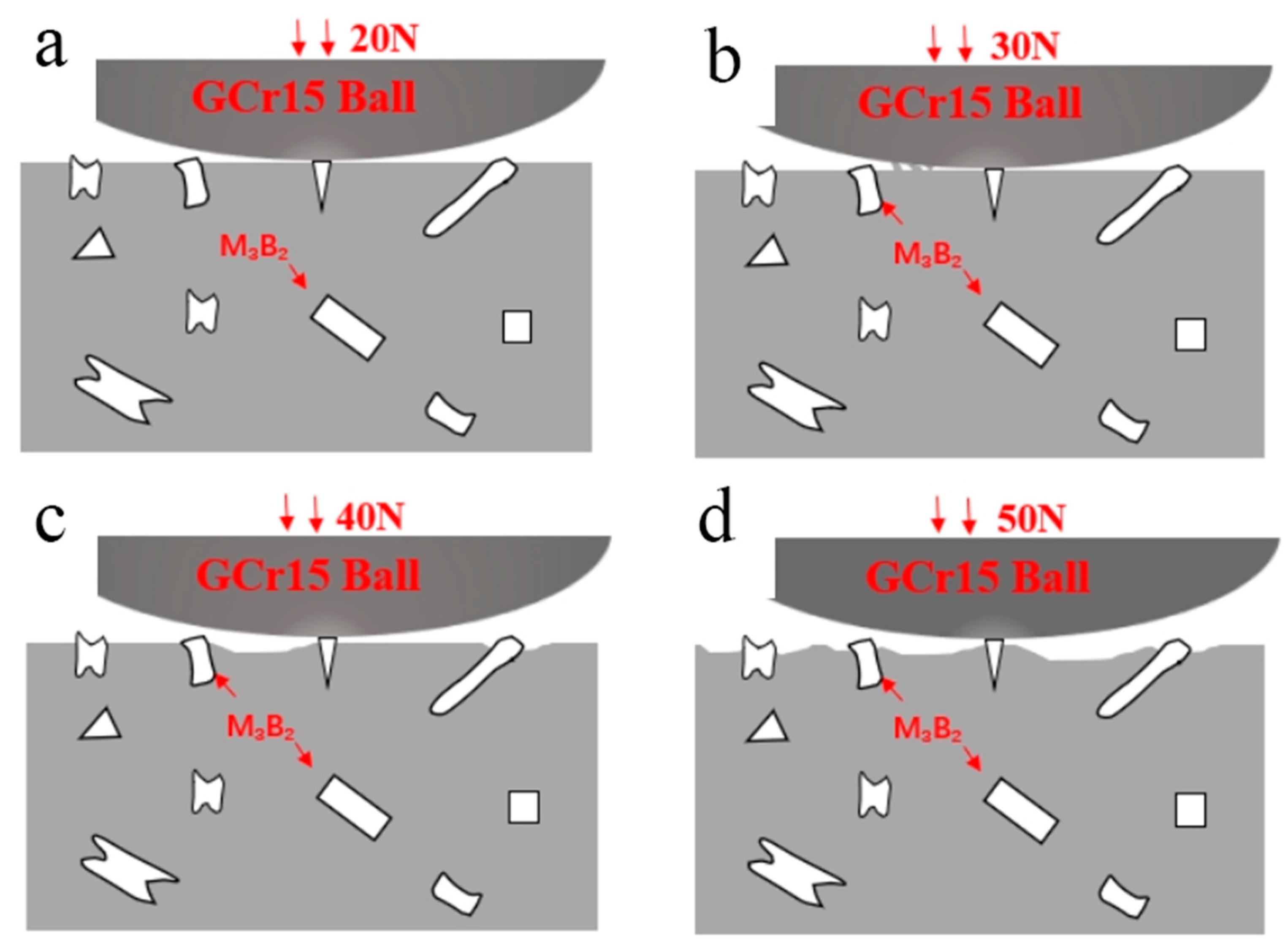
| Load | Width of Wear Scar/mm | Wear Volume /mm3 | Wear Rate/(mm3·N−1·m−1) | Friction Coefficient |
|---|---|---|---|---|
| 20 N | 0.69 | 0.00245 | 1.134 × 10⁻⁶ | 0.7375 |
| 30 N | 0.84 | 0.00568 | 1.753 × 10⁻⁶ | 0.4950 |
| 40 N | 0.92 | 0.00771 | 1.784 × 10⁻⁶ | 0.4408 |
| 50 N | 1.08 | 0.01172 | 2.171 × 10⁻⁶ | 0.4178 |
Publisher’s Note: MDPI stays neutral with regard to jurisdictional claims in published maps and institutional affiliations. |
© 2022 by the authors. Licensee MDPI, Basel, Switzerland. This article is an open access article distributed under the terms and conditions of the Creative Commons Attribution (CC BY) license (https://creativecommons.org/licenses/by/4.0/).
Share and Cite
Chen, J.; Zhang, F.; Ren, X.; Wu, Y.; Han, S.; Cai, M.; Li, Z.; Li, L. Investigation of the Tribological Behavior and Microstructure of Plasma-Cladded Fe–Cr–Mo–Ni–B Coating. Materials 2022, 15, 6595. https://doi.org/10.3390/ma15196595
Chen J, Zhang F, Ren X, Wu Y, Han S, Cai M, Li Z, Li L. Investigation of the Tribological Behavior and Microstructure of Plasma-Cladded Fe–Cr–Mo–Ni–B Coating. Materials. 2022; 15(19):6595. https://doi.org/10.3390/ma15196595
Chicago/Turabian StyleChen, Junfu, Fenglong Zhang, Xianghui Ren, Yaoshen Wu, Shanguo Han, Manxia Cai, Zhenglong Li, and Likun Li. 2022. "Investigation of the Tribological Behavior and Microstructure of Plasma-Cladded Fe–Cr–Mo–Ni–B Coating" Materials 15, no. 19: 6595. https://doi.org/10.3390/ma15196595
APA StyleChen, J., Zhang, F., Ren, X., Wu, Y., Han, S., Cai, M., Li, Z., & Li, L. (2022). Investigation of the Tribological Behavior and Microstructure of Plasma-Cladded Fe–Cr–Mo–Ni–B Coating. Materials, 15(19), 6595. https://doi.org/10.3390/ma15196595