Article

Corrosion Damage and Life Prediction of Concrete Structure in a 41-Year-Old Steelworks

1
School of Civil Engineering, Xi’an University of Architecture and Technology, No. 13 Yanta Rd., Xi’an 710055, China
2
State Key Laboratory of Green Building in Western China, Xi’an University of Architecture and Technology, No. 13 Yanta Rd., Xi’an 710055, China
*
Authors to whom correspondence should be addressed.
Materials 2022, 15(17), 5893; https://doi.org/10.3390/ma15175893
Submission received: 22 June 2022 / Revised: 19 August 2022 / Accepted: 23 August 2022 / Published: 26 August 2022

Abstract

:
Iron and steel industry emits a large amount of CO2 and SO2 in the process of steelmaking, and these acid gases lead to the serious corrosion damage of concrete structures. In this paper, the environmental characteristics and corrosion degree of concrete in a 41-year-old steelworks were investigated, and the neutralization life prediction of the concrete structure was carried out. The results showed that the temperature, relative humidity, CO2 concentration, and SO2 concentration in the steelworks were 1.32, 0.62, 1.28, and 13.93 times higher than those of the general atmospheric environment, respectively. These environmental characteristics in various sections were significantly different. The appearance change of concrete in the ingot casting bay was more serious than that of concrete in the billet bay. Both the compressive strength of concrete in the ingot casting bay and billet bay decreased, and the strength in the billet bay was relatively low. The neutralization depth of concrete in the ingot casting bay was 2.35 times larger than that of concrete in the billet bay. The prediction model of concrete neutralization depth was established, and the remaining neutralization service life in the ingot casting bay and billet bay were 194.68 a and 202.07 a, respectively.

1. Introduction

Steel is the most widely used and consumed alloy in the world. China is the largest steel producer in the world [1]. The steel output of China was 996 million tons in 2019, which accounted for 53.3% of the global steel output [2]. The main energy source of China’s iron and steel sector is coal [3], and CO2 and SO2 are emitted in the process of combustion. Moreover, iron ore contains the sulfur element, which inevitably produces SO2 in the process of mining and processing [4]. According to statistics, China’s total CO2 emissions in 2019 were 11.198 billion tons [5], and the CO2 emissions that generated by China’s steel industry accounted for 14% of total CO2 emissions [6]. The SO2 emissions generated by China’s steel industry in 2015 were 1.37 million tons, which accounted for 7.36% of China’s total SO2 emissions [7].
The pore-solution pH of ordinary Portland cement concrete is usually between 12.5 to 13.5 [8], and this high alkalinity environment prevents the protective film of iron oxides around rebars from destroying [9]. CO2 and SO2 can react with alkaline hydration products. Thrangavel [10] found that CO2 reacted with Ca(OH)2 and decreased the pore-solution pH of concrete, and Niu [11] and Pavlik [12] found that SO2 could also reduce the alkalinity of concrete. Once pore-solution pH drops to about 9, the protective film of the rebars is destroyed, and the rebars begin to corrode [13]. The corrosion products accumulate in the pore structure and generate expansion pressure on the surrounding concrete [14]. Excessive pressure leads to the initiation and propagation of cracks in concrete, thereby reducing the load carrying capacity of concrete structures. Therefore, it is necessary to develop strategies for the CO2 and SO2 resistance of concrete. To achieve this goal, the study on the neutralization of concrete under the combined action of CO2 and SO2 should be accomplished.
At present, the research on concrete neutralization mainly focuses on the action of single CO2 or SO2. According to the theoretical analysis [15], laboratory accelerated test [16,17], and field investigation [18,19] of concrete carbonation, CO2 reacted with calcium compounds of hydration products to form CaCO3. SO2 reacted with all calcium compounds, including CaCO3, and converted them into calcium sulfates and calcium sulfoaluminates [20]. Calcium sulfoaluminates were stable in a certain pH range [21]. Once pH fell to a certain value, calcium sulfoaluminates decomposed. It was reported that the decomposition of ettringite and monosulfoaluminate hydrate at 20 °C were at pH ≤ 10.7 and pH ≤ 11.6, respectively [22]. The decomposition products were gypsum, alumina gel, and water [23]. CaCO3 increased the compactness of concrete, so the carbonation of concrete increased the compressive strength. Li [24] and Rostami [25] verified this conclusion through a carbonation test. Calcium sulfates and calcium sulfoaluminates greatly increased the solid volume of concrete, and the mass and compressive strength increased at first and then decreased [26].
There is little research on concrete neutralization under the combined action of CO2 and SO2, mainly focusing on the neutralization mechanism. Pavlik [12] investigated the degradation of concrete by flue gases in a power plant. The results showed that the corroded concrete was divided into a soft disintegrated zone, sulfated zone and carbonated zone. Scholl [27] found that the corrosion products of concrete were calcite, gypsum, and ettringite under the combined action of SO2 and CO2. Lean [28] observed that the diffusion rate of CO2 in concrete was faster than that of SO2 at the same volume concentration. Furthermore, the concentration of CO2 was higher than that of SO2 in an industrial environment. Therefore, the essence of concrete sulfuration was the reaction between SO2 and carbonation products under the action of CO2 and SO2.
To sum up, there are few research results on the concrete neutralization under the combined action of CO2 and SO2, especially in terms of the degree of concrete performance degradation. Therefore, the corrosion damage and life prediction of concrete structures in a 41-year-old steelworks of Wuhan Iron and Steel Corp. (WISCO) were studied in the present work. The environmental characteristics such as temperature, relative humidity, CO2 concentration, and SO2 concentration in various sections of the steelworks were monitored, respectively. The appearance, cover thickness, neutralization depth, and compressive strength of concrete in the ingot casting bay and billet bay were analyzed, respectively. The prediction model of neutralization depth of concrete in the steelworks was established, and the remaining neutralization service life in the ingot casting bay and billet bay were predicted.

2. Materials and Methods

The industrial environment of steelworks is a typical environment with high temperatures and high concentrations of acid gas. The temperatures of molten iron and molten steels are 1250–1350 °C and 1600–1700 °C, respectively. Therefore, steelworks are exposed to a high-temperature environment for a long time. Besides, a large amount of acid gases, such as CO2 and SO2, are generated in the process of steelmaking. Therefore, the corrosion damage to concrete structures in the steelworks is serious. Taking a 41-year-old steelworks of WISCO as an example, the research group investigated the environmental characteristics and corrosion damage of concrete structures from August to October 2013.

2.1. Project Brief

WISCO was located in Qingshan District, Wuhan City. The main building of the steelworks was built in 1972, and it was divided into seven sections: charging bay, acceptance bay, converter bay, casting bay, ingot casting bay, billet bay, and granulating slag bay. Among them, the ingot casting bay and billet bay were the concrete bent construction. The ingot casting bay was a single slope bent structure with a span of 24 m and a column spacing of 37. The bent frame column of the billet bay adopted the diagonal web member double-wing column.

2.2. Materials

The concrete consisted of ordinary Portland cement, with natural river sand as the fine aggregate and crushed limestone as the coarse aggregate. Both the design thicknesses of concrete cover in the ingot casting bay and billet bay were 30 mm, and the concrete mark of the column was 400. According to Chinese standard GB 50010-2010 [29], the characteristic value of concrete compressive strength was 38 MPa.

2.3. Experimental Methods

2.3.1. Temperature Monitoring

The temperature in the steelworks was tested by the temperature and humidity recorder (8829, AZ Instrument, Taichung, China), and the data were collected hourly. The layout of measuring points was based on the Chinese standard GB/T 18204.13-2000 [30]. There were five measuring points in each section of the steelworks, and they were arranged on two diagonals with the shape of plum blossom. The height of measuring points was 0.8–1.6 m from the ground, and the distance between the measuring points and the heat source or wall was not less than 0.5 m. The average of all measuring points in each section was the average temperature in the section. The average of all sections was the average temperature in the steelworks.

2.3.2. Relative Humidity Monitoring

The relative humidity in the steelworks was tested by the temperature and humidity recorder, and the data were collected hourly. The arrangement of measuring points was the same as that of measuring points for temperature monitoring. The average of all measuring points in each section was the average relative humidity in the section. The average of all sections was the average relative humidity in the steelworks.

2.3.3. CO2 Concentration Monitoring

The CO2 concentration in the steelworks was monitored by using the carbon dioxide detector (7752, AZ Instrument, Taichung, China), and the data were collected hourly. The layout of measuring points was the same as that of measuring points for temperature monitoring. The average of all measuring points in each section was the average CO2 concentration in the section, and the average of all sections was the average CO2 concentration in the steelworks.

2.3.4. SO2 Concentration Monitoring

The SO2 concentration in the steelworks was monitored by using the sulfur dioxide detector (HD5, Huideng, Nanjing, China), and the data were collected hourly. The layout of measuring points was the same as that of measuring points for temperature monitoring. The average of all measuring points in each section was the average SO2 concentration in the section, and the average of all sections was the average SO2 concentration in the steelworks.

2.3.5. Thickness of Concrete Cover

The thickness of concrete cover in the steelworks was tested by a rebar scanner (PROFOMETER-5, Proceq, Schweitzenbach, Switzerland) with a measuring range of 70 mm. Concrete columns were randomly selected to test the thickness of concrete cover. Each column had 30 testing zones, which were evenly distributed on two symmetrical measurable surfaces of the column. The thickness of concrete cover in each testing zone was tested along the direction of the main reinforcement of the column, and the average value of all testing zones in each column was the average thickness of concrete cover of the column.

2.3.6. Neutralization Depth of Concrete

The neutralization depth test method of concrete in Chinese standard JCJ/T 23-2011 [31] was adopted in this experiment. The selection of the concrete columns was the same as that of the columns for testing the thickness of concrete cover. There were three testing zones in each column. Take a hole with a diameter of 15 mm in each testing zone, and the depth of the hole should be larger than its neutralization depth. Measure the neutralization depth with a 1–2% phenolphthalein alcohol solution (alcohol solution contains 20% distilled water). The test was carried out by using a carbonation depth meter (HC-TH01, Hichance, Beijing, China). Each hole was measured three times, and the average of three measurements was considered the neutralization depth of the testing zone. The average of all the testing zones in each column was the neutralization depth of the concrete column.

2.3.7. Compressive Strength of Concrete

The compressive strength of concrete was tested by the rebound method according to JCJ/T 23-2011, and the test was carried out by using a rebound hammer (HT225A, Hichance, Beijing, China). The selection of concrete columns was the same as that of columns for testing the concrete cover thickness. Two testing zones were selected for each column, and they were arranged on two symmetrical measurable surfaces of the column. The measuring points in each testing zone were not less than 16. The measuring points should be evenly distributed, and the distance between two adjacent measuring points should not be less than 20 mm. The distance between the measuring points and the exposed steel bars or embedded parts was not less than 30 mm. The measuring points should not appear on stones and pores, and each measuring point bounced only once. After removing three maximum values and three minimum values, the arithmetic mean value of the remaining measuring points was the average rebound value of the testing zone. The average rebound value of the two testing zones was the final strength of the column. The equivalent value of concrete compressive strength was converted according to the rebound value of compressive strength and the neutralization depth.

3. Results and Discussion

3.1. Survey of Environmental Characteristics

3.1.1. Temperature

The temperature in the steelworks is shown in Figure 1. As shown in the figure, the average temperature in the steelworks was 32.7 °C from August to October 2013. According to the meteorological data, the atmospheric temperature in Wuhan was 24.8 °C during the same period [32]. Therefore, the temperature in the steelworks was 1.32 times higher than that of the general atmospheric environment. Moreover, there were significant differences in the temperatures in various sections. The temperatures in the process sections in front of and in the middle of the furnace, such as the charging bay, acceptance bay, converter bay, casting bay, and ingot casting bay, etc., were higher than those in the post furnace process sections, such as billet bay and granulating slag bay. The temperatures in the charging bay, acceptance bay, converter bay, casting bay, ingot casting bay, billet bay, and granulating slag bay were 40.3, 34.6, 36.4, 31.4, 31.5, 28.3, and 26.5 °C, respectively. The temperature in the charging bay was the highest, and it was 1.63 times higher than that of the general atmospheric environment.

3.1.2. Relative Humidity

The relative humidity in the steelworks is shown in Figure 2. As shown in the figure, the average relative humidity in the steelworks was 45.9% from August to October 2013. According to the meteorological data, the relative humidity of the atmospheric environment in Wuhan was 73.7% during the same period [32]. Therefore, the relative humidity of the general atmospheric environment was 1.61 times higher than that in the steelworks. Besides, the relative humidity in various sections was significantly different, and there was a thermal hydraulic coupled process between relative humidity and temperature. As the temperature increased, the relative humidity showed a downward trend. The relative humidity in the post furnace process sections (billet bay and granulating slag bay) was closed to that of the general atmospheric environment, and the humidity in other sections was much lower than that of the general atmospheric environment. The relative humidity in the billet bay and granulating slag bay were 74.2 and 61.1%, respectively. The relative humidity in the charging bay, acceptance bay, converter bay, casting bay, and ingot casting bay were lower, and they were 27.7, 34.7, 40.3, 42.7, and 40.9%, respectively. The relative humidity in the charging bay was the lowest, and it was 0.38 times higher than that of the general atmospheric environment.

3.1.3. CO2 Concentration

The CO2 concentration in the steelworks is shown in Figure 3. As shown in the figure, the average CO2 concentration in the steelworks was 944.5 mg/m3. According to the relevant information from the Wuhan Environmental Protection Bureau (WHEPB), the CO2 concentration of the atmospheric environment in the Qingshan District was 740.5 mg/m3 [32]. Therefore, the CO2 concentration in the steelworks was 1.28 times higher than that of the general atmospheric environment. In addition, there were significant differences in the CO2 concentrations in various sections, and the CO2 concentrations in the charging bay, acceptance bay, converter bay, casting bay, ingot casting bay, billet bay, and granulating slag bay were 1084.3, 791.2, 1117.6, 974.3, 1039.4, 846.6, and 758.2 mg/m3, respectively. Therefore, CO2 concentration in all sections of the steelworks was higher than that of the general atmospheric environment, and the maximum value was 1.51 times higher than that of the general atmospheric environment.

3.1.4. SO2 Concentration

The SO2 concentration in the steelworks is shown in Figure 4. As shown in the figure, the average SO2 concentration in the steelworks was 0.78 mg/m3. According to the relevant information from WHEPB, the SO2 concentration of the atmospheric environment in the Qingshan District was 0.056 mg/m3 [32]. Therefore, SO2 concentration in the steelworks was 13.93 times higher than that of the general atmospheric environment. There were significant differences in the SO2 concentrations in various sections. The SO2 concentrations in the charging bay, acceptance bay, converter bay, casting bay, and ingot casting bay were 1.29, 1.17, 1.03, 0.96 and 1.03 mg/m3, respectively. No obvious SO2 was detected in the billet bay and granulating slag bay. Therefore, the SO2 concentration in the charging bay was the largest, which was 20.04 times higher than that of the general atmospheric environment.

3.2. Analysis of Corrosion Degree of Concrete Structure

3.2.1. Appearance of Concrete

The appearance of concrete in the ingot casting bay and billet bay of the steelworks is shown in Figure 5. As shown in the figure, although the concrete columns in the ingot casting bay were protected by external bricks, some rebars were still exposed and rusted (Figure 5a). There was some corner damage to the concrete column in the billet bay caused by mechanical collision (Figure 5b). SO2 existed in the ingot casting bay and reacted with hydration products of concrete, resulting in the sulfuration reaction of concrete. Sulfuration could lead to the spalling and damage of concrete [11]. Therefore, the concrete cover fell off, and the rebars were exposed and corroded. However, there was no SO2 in the billet bay, and therefore, there was only some damage on the surface of concrete caused by mechanical collision.

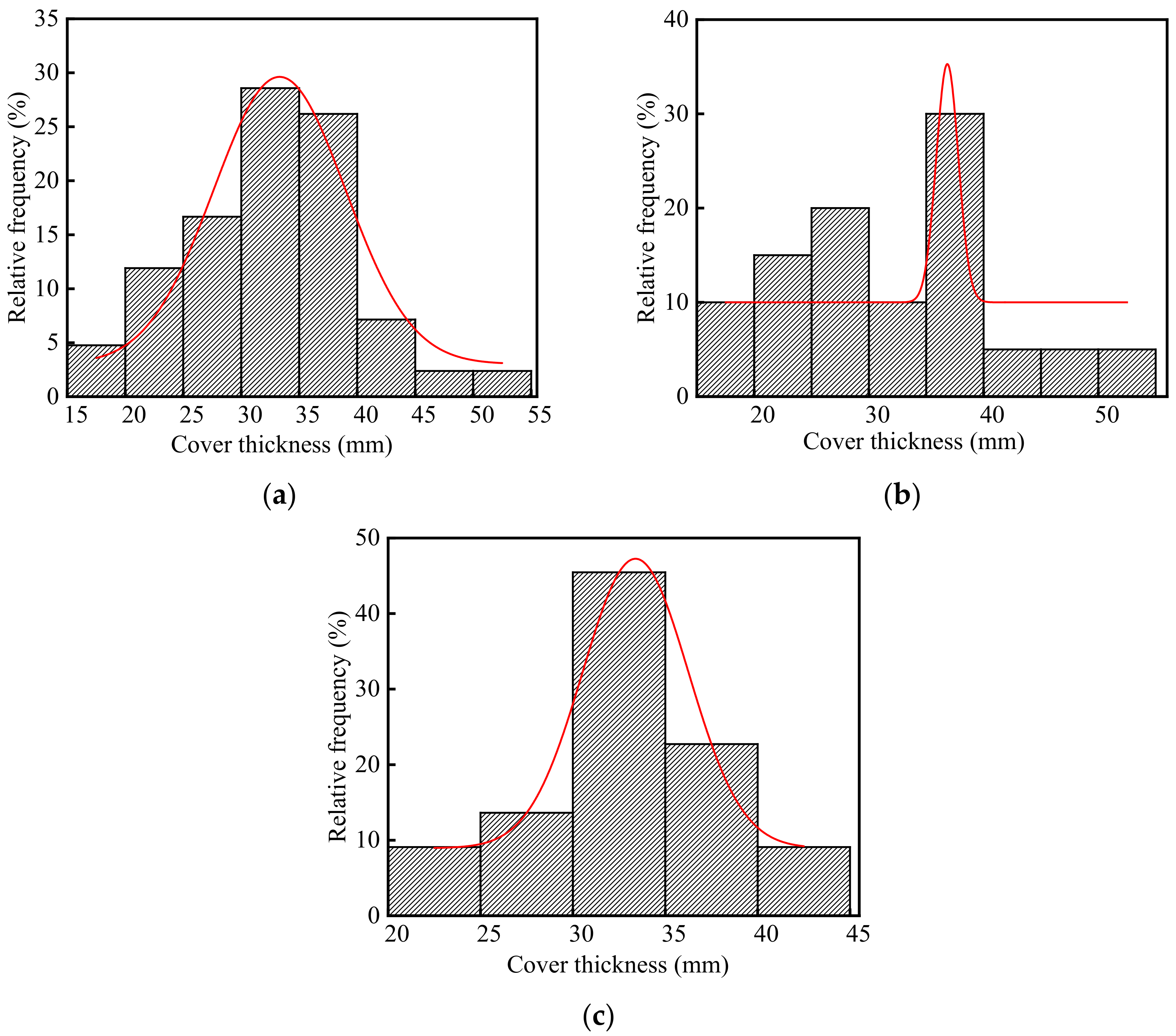
3.2.2. Thickness of Concrete Cover

The thickness of concrete cover in the steelworks is listed in Table S1 (See Supplementary Materials), and the frequency distribution histograms of concrete cover thickness are shown in Figure 6. As shown in Figure 6a, the average thickness of the concrete cover in the steelworks was 32.42 mm, and the ratio of the test value to the design value was 1.08. This indicated that there was little difference between the test value and the design value of the concrete cover thickness in the steelworks. The coefficient of variation of concrete cover thickness was 0.22, indicating that the discreteness of cover thickness was good. It was found that the p-value was 0.81 at a significant level α = 0.05 by using Shapiro-Wilk. Therefore, the thickness of the concrete cover was in accordance with the normal distribution. In summary, the thickness of concrete cover in the steelworks basically met the structural design requirements.
As shown in Figure 6b,c, the average values of concrete cover thickness in the ingot casting bay and billet bay were 32.33 and 32.50 mm, and the coefficients of variation were 0.28 and 0.15, respectively. The results showed that there was little difference between the test value and the design value of the concrete cover thickness in the ingot casting bay and billet bay. By using Shapiro-Wilk, the p values of the concrete cover thickness in the ingot casting bay and billet bay at the significant level α = 0.05 were 0.63 and 0.89, respectively. Therefore, both the thickness of concrete cover in the ingot casting bay and billet bay followed the normal distribution, and they basically met the structural design requirements.

3.2.3. Neutralization Depth of Concrete

The neutralization depth of concrete in the steelworks is listed in Table S1, and the frequency distribution histograms of concrete neutralization depth are shown in Figure 7. The average and standard deviation of concrete neutralization depth in the steelworks were 11.40 and 6.20 mm, respectively. The coefficient of variation was 0.54, and this indicated that the neutralization depth of concrete in the steelworks had a large discreteness. This was because environmental characteristic parameters, especially acid gas concentrations, affected the neutralization depth of concrete. Therefore, the neutralization depth of concrete in different sections varied greatly.
As shown in Figure 7a,b, the neutralization depths in the ingot casting bay and billet bay were different, and the average values were 16.32 and 6.93 mm, respectively. This was because the neutralization depth of concrete increased with the increase in the temperatures [33] and acid gas concentrations [34]. The CO2 concentration and temperature in the ingot casting bay were 1.23 times and 1.11 times higher than those in the billet bay, respectively. In addition, the presence of SO2 in the ingot casting bay led to the cracking of concrete and accelerated the neutralization rate. Therefore, the neutralization depth of concrete in the ingot casting bay was larger, and it was 2.35 times larger than that in the billet bay.
As shown in Figure 7, the p values of neutralization depth in the ingot casting bay and billet bay were 0.30 and 0.13 at the significant level α = 0.05 by using Shapiro-Wilk, respectively. Therefore, the neutralization depth of concrete followed the normal distribution. The coefficients of variation of neutralization depth in the ingot casting bay and billet bay were 0.31 and 0.41, respectively. Therefore, the neutralization depth in the billet bay had a larger discreteness. This was because that one side of the concrete double leg column in the billet bay was in the indoor environment, and the other side was in the outdoor environment with the influence of climate changes, such as rain, temperature changes, freeze-thaw cycles, etc. The neutralization depths of the indoor concrete columns were less than 8 mm, and those of the outdoor concrete columns were more than 10 mm. Therefore, the discreteness of concrete neutralization depth in the billet bay was relatively large.

3.2.4. Compressive Strength of Concrete

The compressive strength of concrete in the steelworks is listed in Table S1, and the frequency distribution histograms of concrete compressive strength are shown in Figure 8. As shown in the figure, the average, standard deviation, and variation of coefficient of the compressive strength were 31.96, 8.39, and 0.26 MPa, respectively. The test value of compressive strength was lower than the design value. On the one hand, the creep stress of concrete structures reduced the compressive strength. On the other hand, the decreasing rate of the strength was accelerated by the influence of SO2 [26] and some environmental changes [35,36], such as temperature changes, rain, and freeze-thaw cycles, etc.
As shown in Figure 8a,b, the average compressive strength in the ingot casting bay was 1.23 times larger than that of compressive strength in the billet bay. Half of the concrete columns in the billet bay were in the outdoor environment, and therefore, the compressive strength in the billet bay decreased more due to the influence of temperature changes, rain, and freeze-thaw cycles.
As shown in Figure 8, the p values of compressive strength in the ingot casting bay and billet bay were 0.17 and 0.78 at the significant level α = 0.05 by using Shapiro-Wilk, respectively. Therefore, the compressive strength of concrete followed the normal distribution. The coefficients of variation of concrete compressive strength in the ingot casting bay and billet bay were 0.16 and 0.32, respectively. The compressive strength in the billet bay had a larger discreteness. This was because that one side of the concrete columns in the billet bay was in the indoor environment, and the other side was in the outdoor environment affected by climate changes. The compressive strength of the indoor concrete was significantly larger than that of the outdoor concrete.

4. Life Prediction of Concrete Structure

4.1. Prediction Model of Neutralization Depth of Concrete

It is verified by a large number of researchers that the carbonation depth of concrete varies linearly with the square root of exposure time [37,38,39,40,41,42,43]. The expression used is given in Equation (1).
X C = k t
where XC is the carbonation depth of concrete, mm; k is the carbonation coefficient, mm/d0.5; t is the carbonation exposure duration, d.
There is only CO2 acid gas in the billet bay, and therefore, the neutralization depth of concrete in the billet bay is the carbonation depth. The carbonation depth of concrete is affected by environmental parameters and material properties. In this paper, temperature, relative humidity, and CO2 concentration are the environmental parameters, and compressive strength is the material property of concrete. Therefore, Equation (1) can be expressed as:
X C = k 0 k 1 k 2 k 3 t
where k0 is the undetermined parameter; k1, k2 and k3 are the carbonation influence coefficients of the temperature and humidity, CO2 concentration and compressive strength, respectively.
According to the literature [43], the carbonation influence coefficients of temperature and humidity, CO2 concentration, and compressive strength can be calculated as follows:
k 1 = 2.56 T 4 R H 1 R H
k 2 = C C 0.03
k 3 = 57.94 f cuk 0.76
where T is the temperature, °C; RH is the relative humidity, %; CC is the concentration of CO2, %; and fcuk is the compressive strength of concrete, MPa.
Substituting Equations (3), (4), and (5) into Equation (2), the carbonation depth of concrete can be expressed as:
X C = k 0 T 4 1 R H R H C C 57.94 f cuk 0.76 t
The neutralization depth of concrete in the billet bay is the carbonation depth. Substituting the test values of the temperature, relative humidity, CO2 concentration, concrete compressive strength, concrete neutralization depths, and neutralization ages in the billet bay into Equation (6), k0 is calculated and the frequency distribution histogram of k0 is shown in Figure 9. As shown in the figure, the average, standard deviation, and coefficient of variation of k0 were 7.66, 3.16, and 0.41, respectively. The p-value of k0 was 0.13 at the significant level α = 0.05 by using Shapiro-Wilk. Therefore, k0 in the steelworks followed the normal distribution.
SO2 concentration in the steelworks is much lower than that of CO2. However, SO2 can lead to the expansion and cracking of concrete, which accelerates the concrete neutralization. Therefore, the neutralization depth of concrete in the ingot casting bay can be expressed as:
X = k 5 X C
where k5 is the neutralization influence coefficient of SO2 concentration.
Substituting the test values of the temperature, relative humidity, CO2 concentration, concrete compressive strength, neutralization ages in the ingot casting bay into Equation (6), the average of carbonation depth of concrete in the ingot casting bay is 9.97 mm. Combining the average carbonation depth and the neutralization depths of concrete in the ingot casting bay, k5 is calculated and the frequency distribution histogram of k5 is shown in Figure 10. As shown in the figure, the average, standard deviation, and coefficient of variation of k5 were 1.64, 0.50, and 0.31, respectively. The p-value of k5 was 0.30 at the significant level α = 0.05 by using Shapiro-Wilk. Therefore, k5 in the steelworks followed the normal distribution.
In conclusion, the neutralization depth of concrete in the steelworks is expressed as:
X t = k 0 k 5 T 4 1 R H R H C C 57.94 f cuk 0.76 t
when CS = 0, k5 = 1.

4.2. Neutralization Life Prediction of Concrete Structure

CO2 and SO2 diffuse into concrete and react with the alkaline hydration products. Once the concrete cover is completely neutralized, the protective effect on the rebars is lost, and therefore, the rebars begin to corrode. The neutralization service life of concrete takes the initial time of steel bar corrosion as the end of the structural life. Therefore, the beginning of the steel bar corrosion is the sign of neutralization service life assessment criteria of concrete structure.
Ω = c x 0 X t 0
where, Ω is the neutralization service life criteria of concrete; c is the thickness of concrete cover, mm; x0 is the neutralization remain, mm; X(t) is the neutralization depth of concrete, mm; and t is the neutralization age, d.
Therefore, the limit state function of the neutralization service life of concrete is:
c x 0 X t = 0
According to the literature [43], the neutralization remain of concrete is:
x 0 = 4.86 R H 2 + 1.5 R H 0.45 c 5 ln f cuk 2.3
Neutralization remains of concrete in the ingot casting bay and billet bay of the steelworks are calculated according to Equation (11). The frequency distribution histograms of x0 are shown in Figure 11. As shown in the figure, there were significant differences in x0 between the ingot casting bay and billet bay, and x0 in the billet bay was much larger than that in the ingot casting bay. The average, standard deviation, and coefficient of variation of x0 in the ingot casting bay were −0.67, 0.22, and −0.33 mm, respectively. As well, the average, standard deviation, and coefficient of variation of x0 in the billet bay were 20.10, 3.66, and 0.18 mm, respectively. This was because the relative humidity in the billet bay was much larger than that in the ingot casting bay. The p values of x0 in the ingot casting bay and billet bay were 0.63 and 0.89 at the significant level α = 0.05 by using Shapiro-Wilk, respectively. Therefore, both neutralization remains of concrete in the ingot casting bay and billet bay followed the normal distribution.
Substituting the calculation results of Equations (8) and (11) into Equation (10), the neutralization service life of concrete in the ingot casting bay and billet bay of the steelworks were 235.68 a and 243.07 a, respectively. Therefore, the remaining neutralization service life in the ingot casting bay and billet bay were 194.68 a and 202.07 a, respectively.

5. Conclusions

In this study, the environmental characteristics and corrosion degree of concrete in a 41-year-old steelworks were analyzed, and the neutralization life prediction of the concrete structure was carried out. The average temperature, relative humidity, CO2 concentration, and SO2 concentration in the steelworks were 1.32, 0.62, 1.28, and 13.93 times higher than those of the general atmospheric environment, respectively. Besides, those environmental parameters in various sections were significantly different. The temperature, relative humidity, and CO2 concentration in the ingot casting bay were 1.11, 0.55, and 1.23 times higher than those in the billet bay, respectively. The SO2 concentration in the ingot casting bay was 1.03 mg/m3, and there was no obvious SO2 in the billet bay. The appearance change of concrete in the ingot casting bay was more serious than that of concrete in the billet bay. Both the compressive strength of concrete in the ingot casting bay and billet bay of the steelworks decreased, and the compressive strength in the ingot casting bay was 1.23 times larger than that in the billet bay. The neutralization depth in the ingot casting bay was 2.35 times higher than that in the billet bay. The prediction model of the neutralization depth of concrete was established, and the remaining neutralization service life of concrete in the ingot casting bay and billet bay were 194.68 a and 202.07 a, respectively.

Supplementary Materials

The following supporting information can be downloaded at: https://www.mdpi.com/article/10.3390/ma15175893/s1, Table S1: The cover thickness, neutralization depth and compressive strength of concrete in the steelworks.

Author Contributions

Conceptualization, Y.L. and D.N.; Data curation, Y.L., D.N. and X.L.; Funding acquisition, D.N. and X.L.; Investigation, Y.-C.L.; Methodology, Y.L.; Writing—original draft, Y.L.; Writing—review & editing, Y.L. All authors have read and agreed to the published version of the manuscript.

Funding

This research was financially supported by the National Natural Science Foundation of China (Grant No. 52078413), the Program for Innovative Research Team in University of Ministry of Education of China (Grant No. IRT17R84), the National Natural Science Foundation of China (Grant No. 52178163).

Institutional Review Board Statement

Not applicable.

Informed Consent Statement

Not applicable.

Data Availability Statement

Data are real and valid in the article.

Acknowledgments

The authors thank all the anonymous reviewers for helping improve this paper.

Conflicts of Interest

The authors declare no conflict of interest.

References

  1. International Energy Agency. Iron and Steel Technology Roadmap: Towards More Sustainable Steelmaking; International Energy Agency: Paris, France, 2020. [Google Scholar]
  2. World Steel Association. Steel Statistical Yearbooks; World Steel Association: Brussels, Belgium, 2020. [Google Scholar]
  3. International Energy Agency. World Energy Balances; International Energy Agency: Paris, France, 2020. [Google Scholar]
  4. Long, Y.; Pan, J.; Farooq, S.; Boer, H. A sustainability assessment system for Chinese iron and steel firms. J. Clean. Prod. 2016, 125, 133–144. [Google Scholar] [CrossRef]
  5. International Energy Agency. World Energy Outlook; International Energy Agency: Paris, France, 2021. [Google Scholar]
  6. Ren, M.; Lu, P.; Liu, X.; Hossain, M.; Fang, Y.; Hanaoka, T.; O’Gallachoir, B.; Glynn, J.; Dai, H. Decarbonizing China’s iron and steel industry from the supply and demand sides for carbon neutrality. Appl. Energy 2021, 298, 117209. [Google Scholar] [CrossRef]
  7. Ministry of Environmental Protection, the People’s Republic of China. Report on the State of the Environment in China; Ministry of Ecology and Environment of the People’s Republic of China: Beijing, China, 2015.
  8. Papadakis, V.G.; Vayenas, C.G.; Fardis, M.N. A reaction engineering approach to the problem of concrete carbonation. AIChE J. 1989, 35, 1639–1650. [Google Scholar] [CrossRef]
  9. Thangavel, K. The Threshold Limit for Chloride Corrosion of Reinforced Concrete. Corros. Rev. 2004, 22, 55–70. [Google Scholar] [CrossRef]
  10. Visser, J. Influence of the carbon dioxide concentration on the resistance to carbonation of concrete. Constr. Build. Mater. 2014, 67, 8–13. [Google Scholar] [CrossRef]
  11. Niu, D.; Lv, Y.; Liu, X.; Chen, L.; Chen, G.; Zhang, B. Study on the Sulfuration Mechanism of Concrete: Microstructure and Product Analysis. Materials 2020, 13, 3386. [Google Scholar] [CrossRef]
  12. Pavlík, V.; Bajza, A.; Rouseková, I.; Unčík, S.; Dubík, M. Degradation of concrete by flue gases from coal combustion. Cem. Concr. Res. 2007, 37, 1085–1095. [Google Scholar] [CrossRef]
  13. Pourbaix, M. Applications of electrochemistry in corrosion science and in practice. Corros. Sci. 1974, 14, 25–82. [Google Scholar] [CrossRef]
  14. Fu, C.; Fang, D.; Ye, H.; Huang, L.; Wang, J. Bond degradation of non-uniformly corroded steel rebars in concrete. Eng. Struct. 2021, 226, 111392. [Google Scholar] [CrossRef]
  15. Papadakis, V.; Vayenas, C.; Fardis, M. Physical and chemical characteristics affecting the durability of concrete. ACI Mater. J. 1991, 88, 186–196. [Google Scholar]
  16. Chang, C.-F.; Chen, J.-W. The experimental investigation of concrete carbonation depth. Cem. Concr. Res. 2006, 36, 1760–1767. [Google Scholar] [CrossRef]
  17. Kobayashi, K.; Suzuki, K.; Uno, Y. Carbonation of concrete structures and decomposition of C-S-H. Cem. Concr. Res. 1994, 24, 55–61. [Google Scholar] [CrossRef]
  18. Liu, X.; Niu, D.; Li, X.; Lv, Y.; Fu, Q. Pore Solution pH for the Corrosion Initiation of Rebars Embedded in Concrete under a Long-Term Natural Carbonation Reaction. Appl. Sci. 2018, 8, 128. [Google Scholar] [CrossRef]
  19. Liu, X.; Niu, D.; Li, X.; Lv, Y. Effects of Ca(OH)2–CaCO3 concentration distribution on the pH and pore structure in natural carbonated cover concrete: A case study. Constr. Build. Mater. 2018, 186, 1276–1285. [Google Scholar] [CrossRef]
  20. Mainier, F.B.; Almeida, P.C.F.; Nani, B.; Fernandes, L.H.; Reis, M.F. Corrosion Caused by Sulfur Dioxide in Reinforced Concrete. Open J. Civ. Eng. 2015, 5, 379–389. [Google Scholar] [CrossRef]
  21. Damidot, D.; Glasser, F.P. Thermodynamic investigation of the CaO·Al2O3·CaSO4·H2O system at 50 °C and 85 °C. Cem. Concr. Res. 1992, 22, 1179–1191. [Google Scholar] [CrossRef]
  22. Gabrisová, A.; Havlica, J.; Sahu, S. Stability of calcium sulphoaluminate hydrates in water solutions with various pH values. Cem. Concr. Res. 1991, 21, 1023–1027. [Google Scholar] [CrossRef]
  23. Shi, C.; Stegemann, J. Acid corrosion resistance of different cementing materials. Cem. Concr. Res. 2000, 30, 803–808. [Google Scholar] [CrossRef]
  24. Li, Y.; Wang, R.; Zhao, Y. Effect of coupled deterioration by freeze-thaw cycle and carbonation on concrete produced with coarse recycled concrete aggregates. J. Ceram. Soc. Jpn. 2017, 125, 36–45. [Google Scholar] [CrossRef]
  25. Rostami, V.; Shao, Y.; Boyd, A.J. Carbonation Curing versus Steam Curing for Precast Concrete Production. J. Mater. Civ. Eng. 2012, 24, 1221–1229. [Google Scholar] [CrossRef]
  26. Niu, J.; Wu, B.; Zhu, C.; Yang, P. Corrosion rules for ordinary concrete exposed to sulfur dioxide-containing environments. Toxicol. Environ. Chem. 2015, 97, 367–378. [Google Scholar] [CrossRef]
  27. Scholl, E.; Knöfel, D. On the effect of SO2 and CO2 on cement paste. Cem. Concr. Res. 1991, 21, 127–136. [Google Scholar] [CrossRef]
  28. Alekseyev, C.H. Corrosion and Protection of Steel Bar in Reinforced Concrete Structure; Huang, X., Wu, X., Jiang, R., Eds.; China Building Industry Press: Beijing, China, 1983. (In Chinese) [Google Scholar]
  29. GB 50010-2010; Code for Design of Concrete Structures. China Building Industry Press: Beijing, China, 2010. (In Chinese)
  30. GB/T 18204.13-2000; Methods for Determination of Air Temperature in Public Places. China Standards Press: Beijing, China, 2000. (In Chinese)
  31. JCJ/T 23-2011; Technical Specification for Inspecting of Concrete Compressive Strength by Rebound Method. China Building Industry Press: Beijing, China, 2011. (In Chinese)
  32. Li, Y. Research on Environmental Zonation of Concrete Structures Durability in Wuhan Iron and Steel Industrial Estates; Academic Press: Cambridge, MA, USA; Xi’an University of Architecture and Technology: Xi’an, China, 2014. (In Chinese) [Google Scholar]
  33. Wang, W.; Lu, C.; Li, Y.; Yuan, G.; Li, Q. Effects of stress and high temperature on the carbonation resistance of fly ash concrete. Constr. Build. Mater. 2017, 138, 486–495. [Google Scholar] [CrossRef]
  34. Chen, Y.; Liu, P.; Yu, Z. Effects of Environmental Factors on Concrete Carbonation Depth and Compressive Strength. Materials 2018, 11, 2167. [Google Scholar] [CrossRef] [PubMed]
  35. Liu, X.; Ma, E.; Liu, J.; Zhang, B.; Niu, D.; Wang, Y. Deterioration of an industrial reinforced concrete structure exposed to high temperatures and dry-wet cycles. Eng. Fail. Anal. 2022, 135, 106150. [Google Scholar] [CrossRef]
  36. Ji, X.; Song, Y.; Liu, Y. Effect of freeze-thaw cycles on bond strength between steel bars and concrete. J. Wuhan Univ. Technol.-Mater. Sci. Ed. 2008, 23, 584–588. [Google Scholar] [CrossRef]
  37. Khunthongkeaw, J.; Tangtermsirikul, S.; Leelawat, T. A study on carbonation depth prediction for fly ash concrete. Constr. Build. Mater. 2006, 20, 744–753. [Google Scholar] [CrossRef]
  38. Papadakis, V.G.; Vayenas, C.G.; Fardis, M.N. Experimental investigation and mathematical modeling of the concrete carbonation problem. Chem. Eng. Sci. 1991, 46, 1333–1338. [Google Scholar] [CrossRef]
  39. Thiery, M.; Villain, G.; Dangla, P.; Platret, G. Investigation of the carbonation front shape on cementitious materials: Effects of the chemical kinetics. Cem. Concr. Res. 2007, 37, 1047–1058. [Google Scholar] [CrossRef]
  40. Fu, C.; Huang, J.; Dong, Z.; Yan, W.; Gu, X.-L. Experimental and numerical study of an electromagnetic sensor for non-destructive evaluation of steel corrosion in concrete. Sens. Actuators A Phys. 2020, 315, 112371. [Google Scholar] [CrossRef]
  41. Dong, Z.; Gu, X.-L.; Jin, Z.-H.; Poursaee, A.; Ye, H. Experimental and Numerical Investigations on the Rate-Limiting Step for Macrocell Corrosion of Reinforcing Steel in Concrete. J. Mater. Civ. Eng. 2022, 34, 04021407. [Google Scholar] [CrossRef]
  42. Jiang, C.; Huang, Q.; Gu, X.; Zhang, W. Experimental investigation on carbonation in fatigue-damaged concrete. Cem. Concr. Res. 2017, 99, 38–52. [Google Scholar] [CrossRef]
  43. Niu, D. Durability and Life Forecast of Reinforced Concrete Structure; Science Press: Beijing, China, 2003. (In Chinese) [Google Scholar]
Figure 1. The temperature in the steelworks.
Materials 15 05893 g001
Figure 2. Relative humidity in the steelworks.
Materials 15 05893 g002
Figure 3. CO2 concentration in the steelworks.
Materials 15 05893 g003
Figure 4. SO2 concentration in the steelworks.
Materials 15 05893 g004
Figure 5. The appearance of concrete structures in the steelworks: (a) Ingot casting bay; (b) Billet bay.
Materials 15 05893 g005
Figure 6. Frequency distribution histograms of concrete cover thickness in the steelworks: (a) Both in the ingot casting bay and billet bay; (b) Ingot casting bay; (c) Billet bay.
Materials 15 05893 g006
Figure 7. Frequency distribution histograms of concrete neutralization depth in the steelworks: (a) Ingot casting bay; (b) Billet bay.
Materials 15 05893 g007
Figure 8. Frequency distribution histograms of concrete compressive strength in the steelworks: (a) Ingot casting bay; (b) Billet bay.
Materials 15 05893 g008
Figure 9. Frequency distribution histogram of k0.
Materials 15 05893 g009
Figure 10. Frequency distribution histogram of k5.
Materials 15 05893 g010
Figure 11. Frequency distribution histograms of x0 in the steelworks: (a) Ingot casting bay; (b) Billet bay.
Materials 15 05893 g011
Publisher’s Note: MDPI stays neutral with regard to jurisdictional claims in published maps and institutional affiliations.

