
Experimental Research on Flexural Mechanical Properties of Ultrahigh Strength Concrete Filled Steel Tubes

Abstract
:1. Introduction
2. Project Overview
3. Test Design
3.1. Specimen Design and Production
- (1)
- Specimen design
- (2)
- Specimen production
3.2. Material Performance
3.2.1. Steel Tube
3.2.2. Concrete
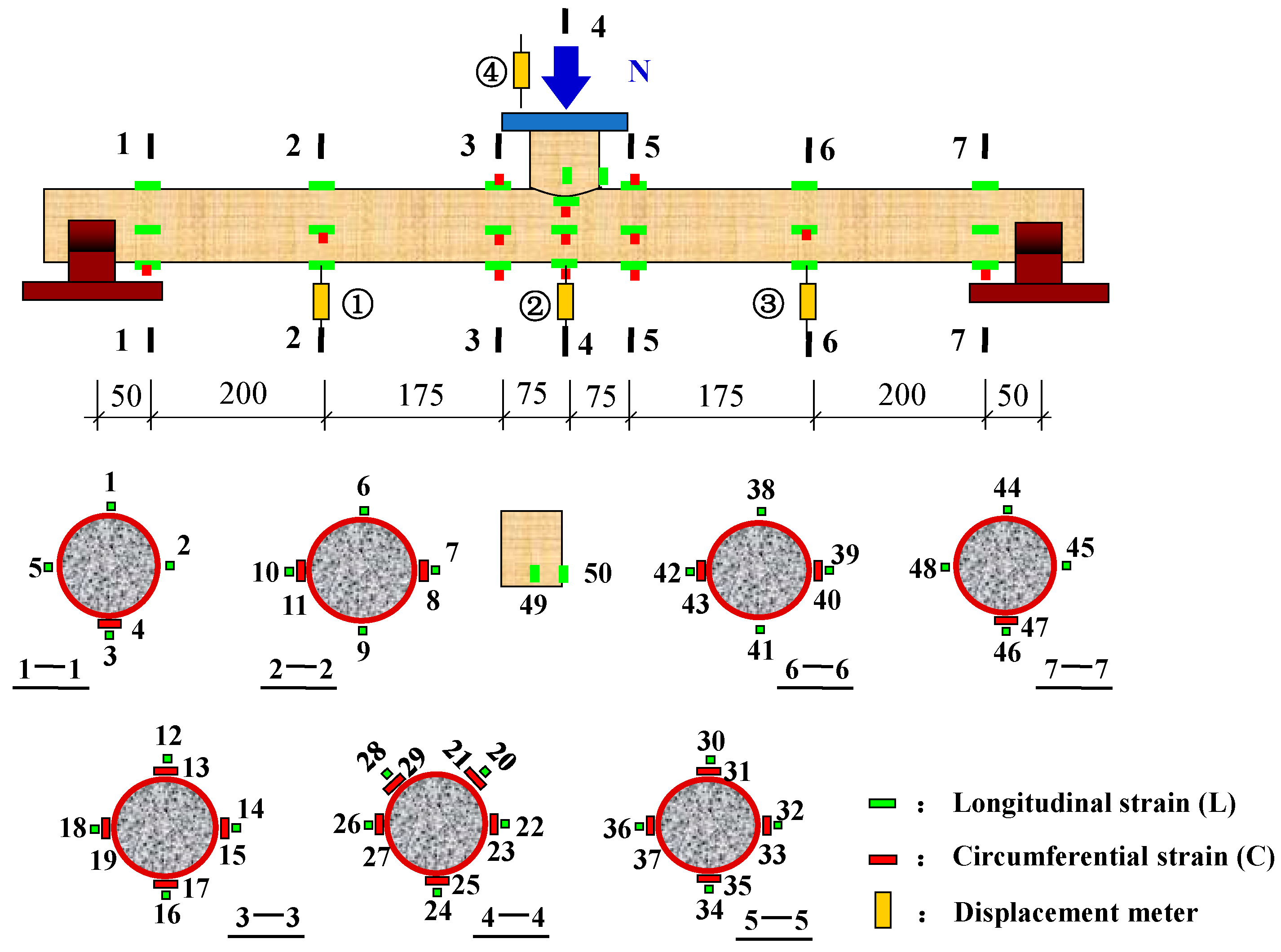
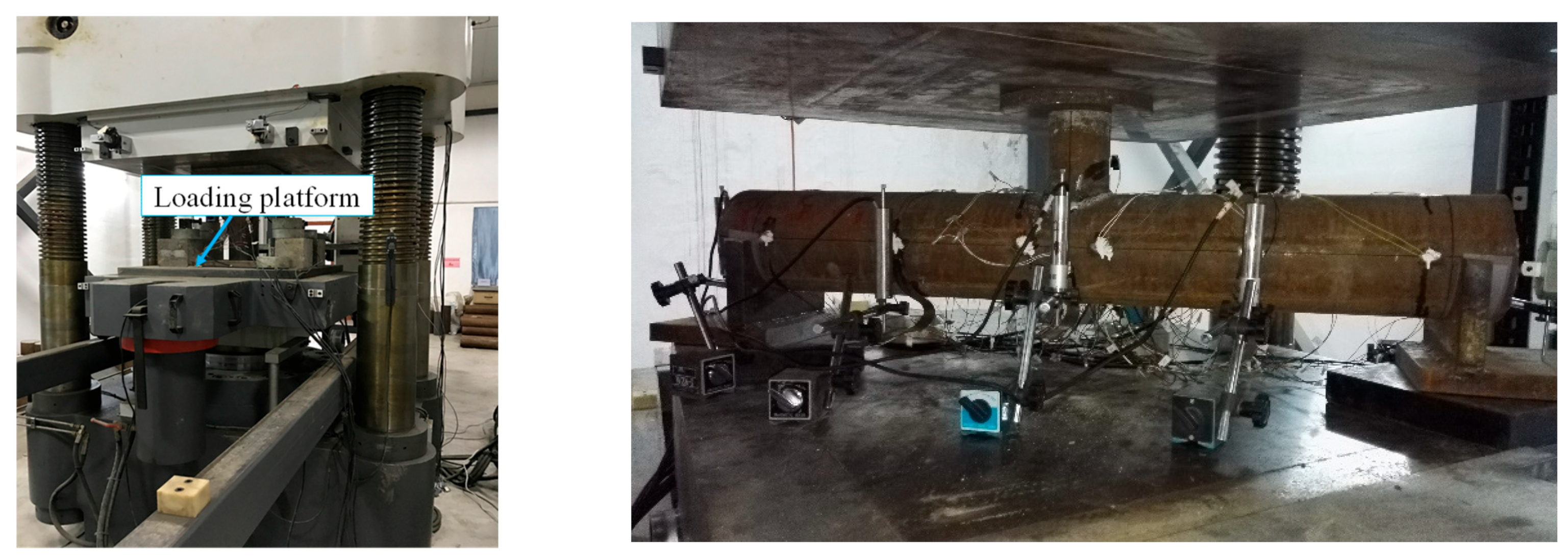
3.3. Test Scheme
- (1)
- Test equipment and measuring points
- (2)
- Loading plan
4. Test Process and Test Result Analysis
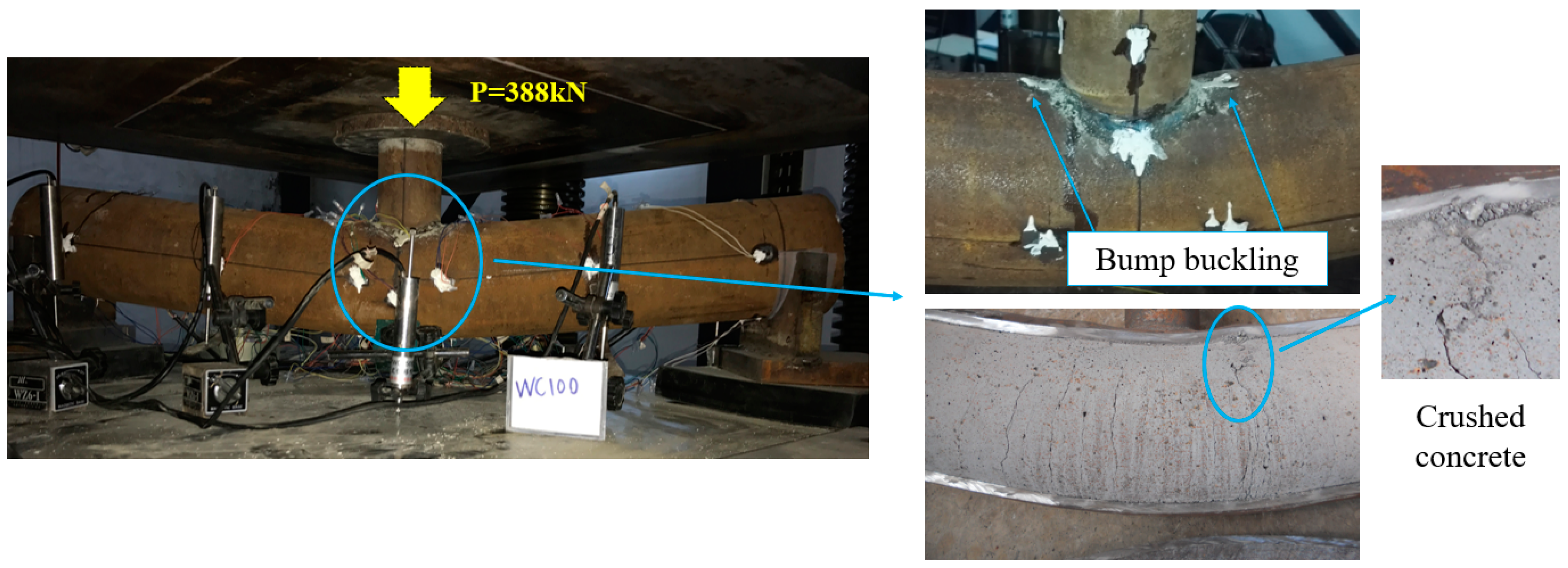
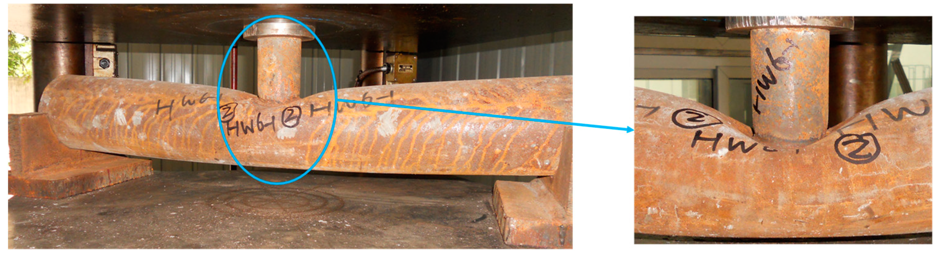
4.1. Loading Process and Failure Mode
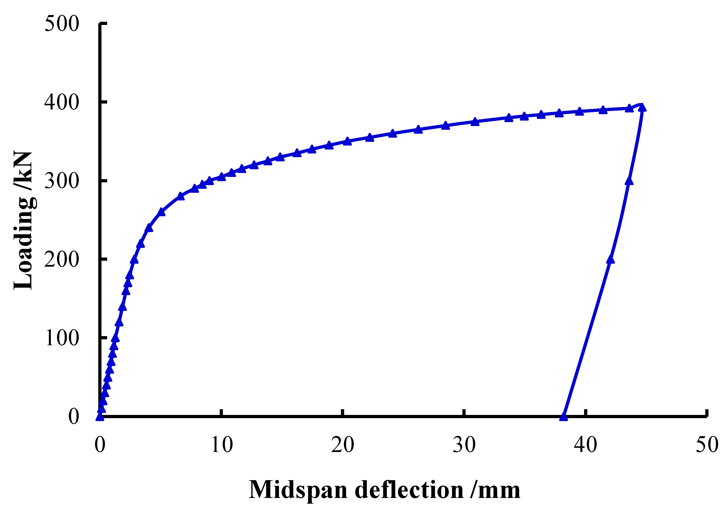
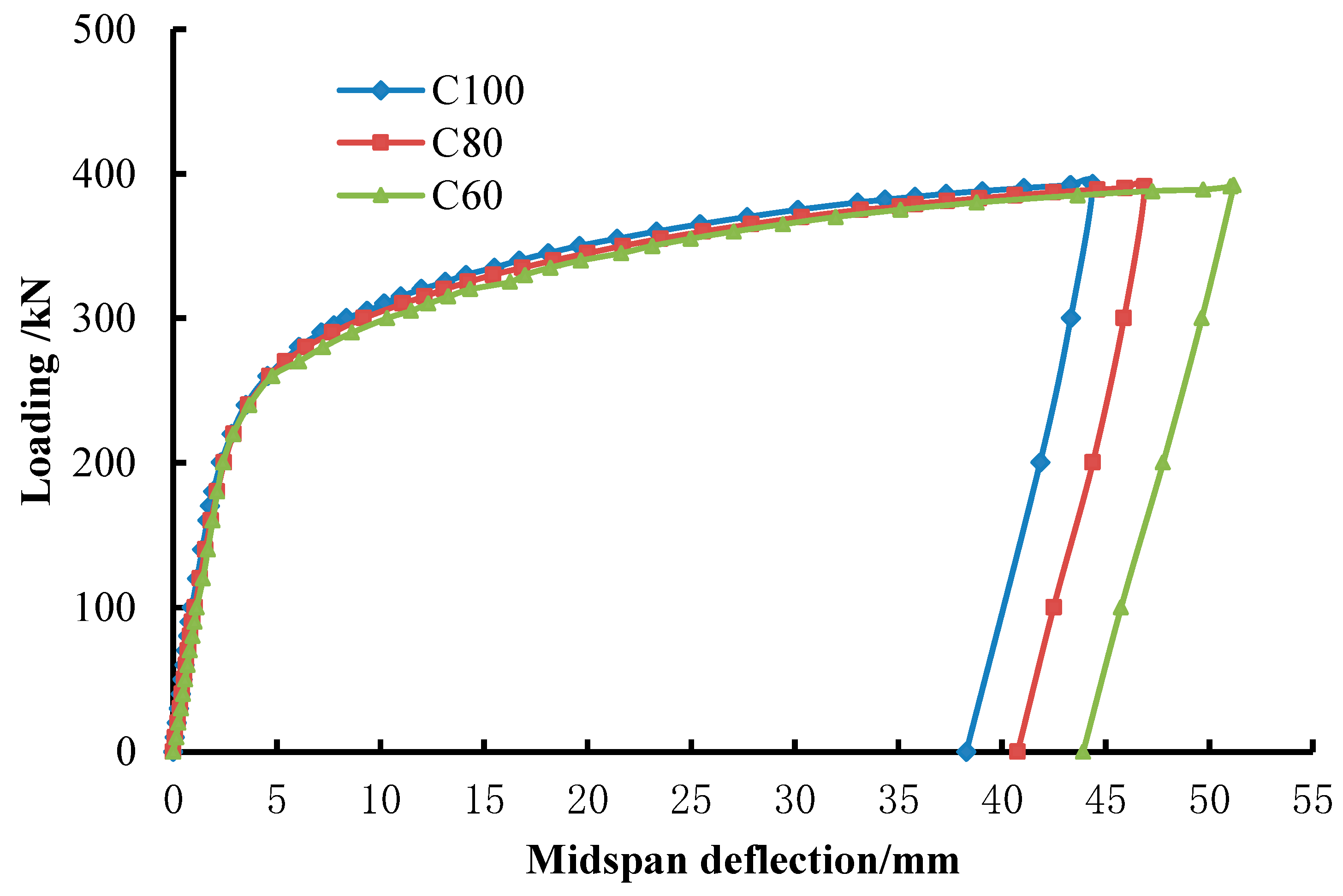
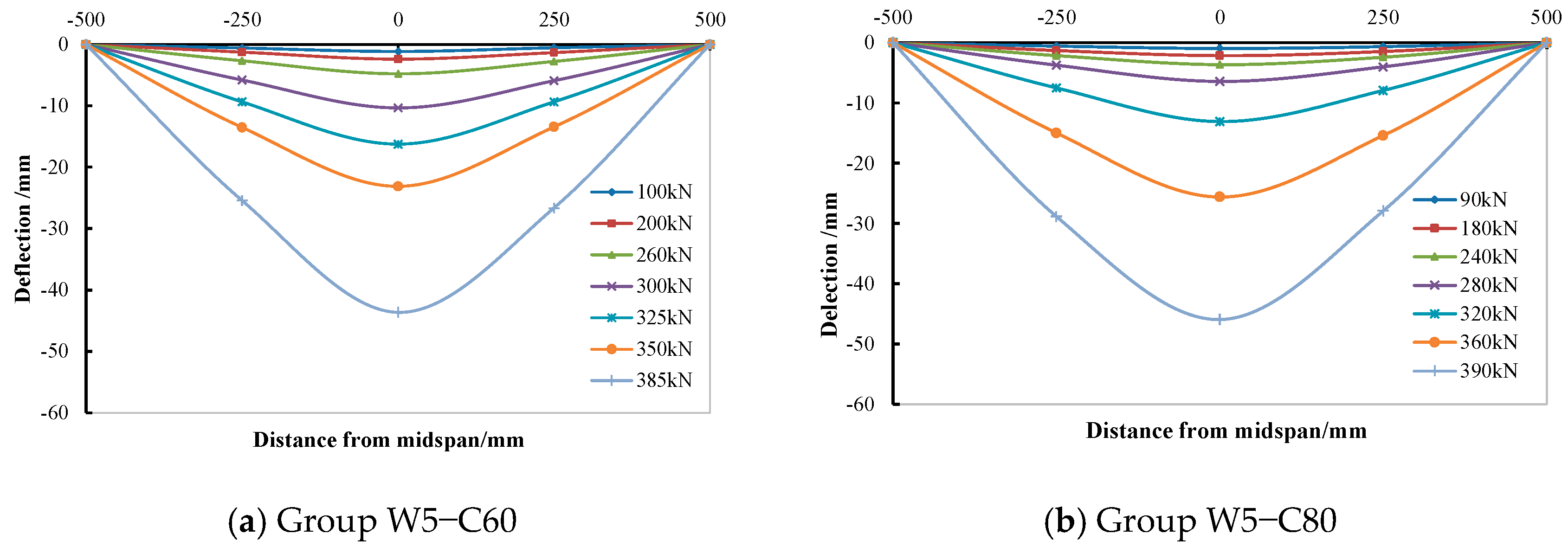
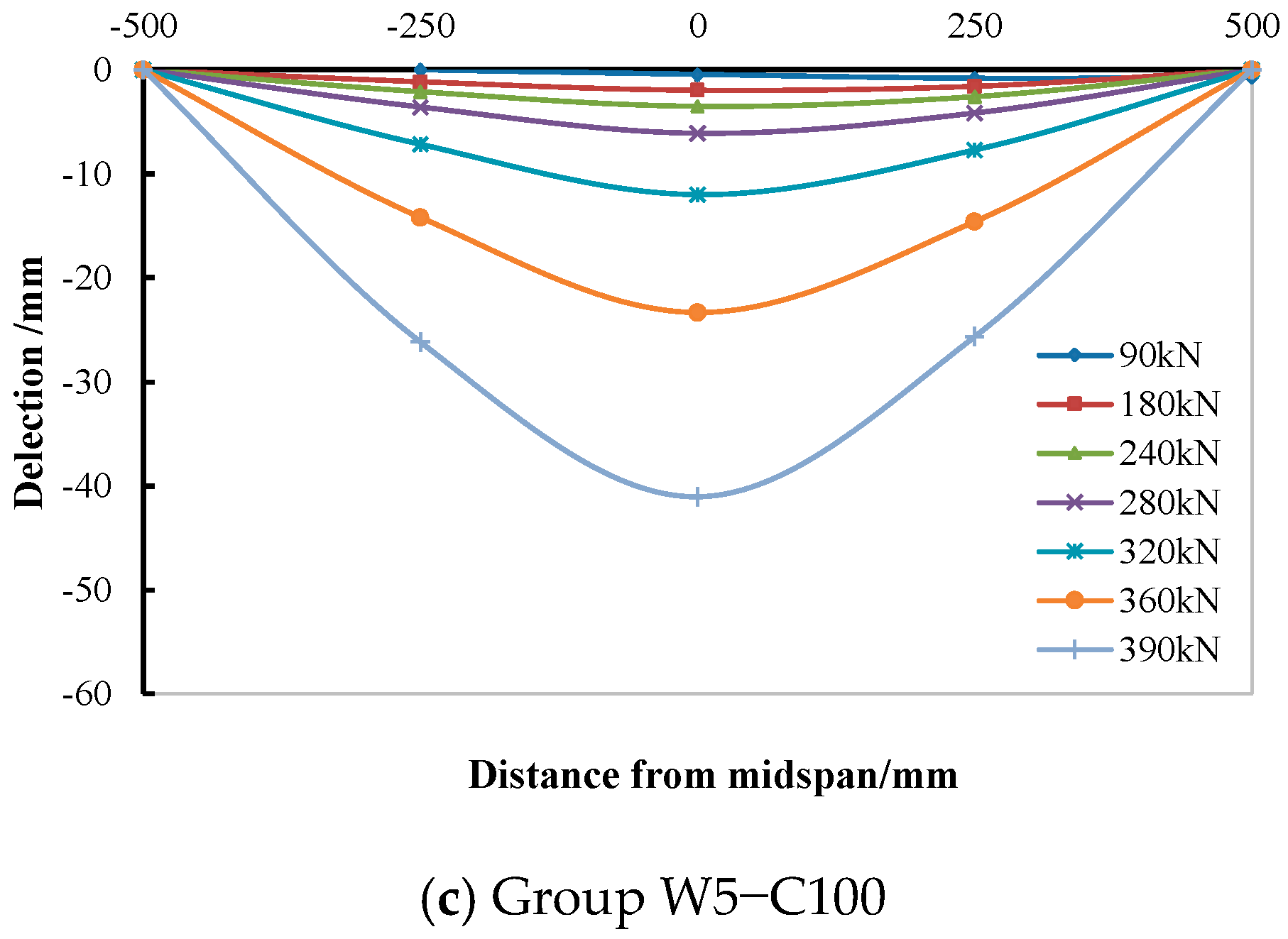
4.2. Load-Deformation Analysis
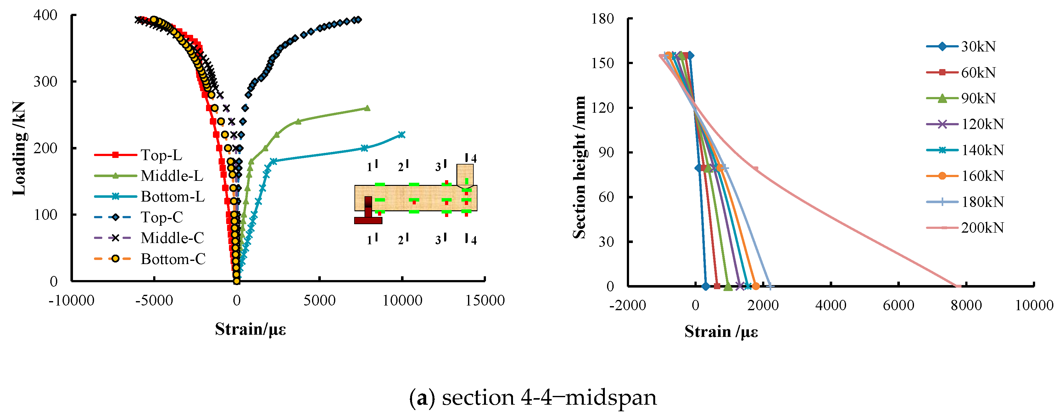
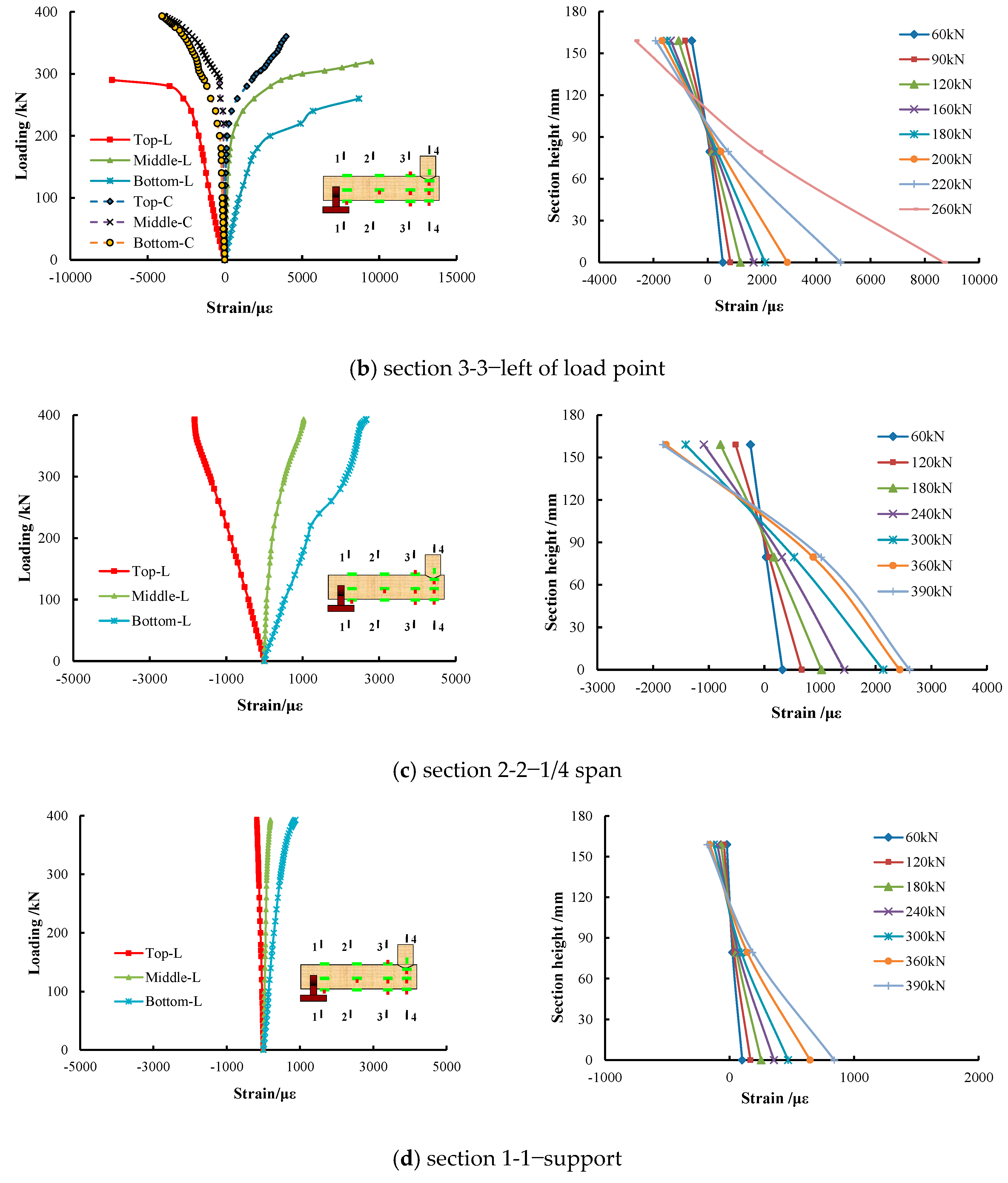
4.3. Section Strain Distribution and Development Analysis
4.4. Discussion on Bearing Capacity and Calculation Method
5. Conclusions
- (1)
- The main failure mode of UHSCFST specimen was the overall bending failure, with slight local buckling in the compression zone, and the integrity of the section was maintained well.
- (2)
- The bending failure mode of UHSCFST members resembled that of ordinary CFST, and core concrete strength had little influence on the bending failure mode of UHSCFST.
- (3)
- UHSCFST had high flexural ductility. After the specimen yielded, the bearing capacity was enhanced slowly with the increase of deflection. The load value presented no reduction until the specimen was destroyed.
- (4)
- The increase of core strength had little effect on the flexural bearing capacity of UHSCFST. The main function of core concrete is to support the steel tube wall, and avoid its local collapse and improve the bending stiffness of composite section. However, this effect tends to be stable with the enhancement of core concrete strength, which should be taken into account in establishing the calculation method of UHSCFST bending capacity.
Author Contributions
Funding
Institutional Review Board Statement
Informed Consent Statement
Data Availability Statement
Conflicts of Interest
References
- Han, L.H.; Zhong, S.T. Mechanics of concrete filled steel tube. Ind. Build. 2004, 34, 62–65. [Google Scholar]
- Zhong, S.T. Concrete Filled Steel Tube Structure; Heilongjiang Science and Technology Press: Harbin, China, 1999. [Google Scholar]
- Zhou, X.J.; Mou, T.M.; Tang, H.; Fan, B. Experimental study on ultra-high strength concrete filled steel tube short columns under axial load. Adv. Mater. Sci. Eng. 2017, 2017, 8410895. [Google Scholar] [CrossRef] [Green Version]
- Han, L.H. Concrete Filled Steel Tubular Structures: Theory and Practice; Science Press: Beijing, China, 2018. [Google Scholar]
- Qian, J.R.; Wang, G.; Zhao, Z.Z.; Zhou, K.Z. Research of section moment-curvature relationship curves of steel tube confined high-strength concrete members. Ind. Constr. 2004, 34, 70–72. [Google Scholar]
- Wang, Q.L.; Dong, Z.F.; Gao, J.Z. Experimental study on concrete filled circular steel tubular flexural members. Sichuan Build. Sci. 2007, 33, 9–13. [Google Scholar]
- Liu, M.H.; Han, B.; Duo, J.T. Investigation on the effect of interface imperfection on the flexural behaviors of concrete filled steel tubular bending members. China Civ. Eng. J. 2019, 6, 55–66. [Google Scholar]
- Flor, J.M.; Fakury, R.H.; Caldas, R.B.; Rodrigues, F.C.; Araújo, A.H.M. Experimental study on the flexural behavior of large-scale rectangular concrete-filled steel tubular beams. Rev. Ibracon Estrut. Mater. 2017, 10, 895–905. [Google Scholar] [CrossRef] [Green Version]
- Ban, L.H.; Lu, H.; Yao, G.H. Further study on the flexural behaviors of concrete-filled steel tubes. J. Constr. Steel Res. 2006, 62, 554–565. [Google Scholar]
- Arivalagan, S.; Kandasamy, S. Flexural behaviour of concrete-filled steel hollow sections beams. J. Civ. Eng. Manag. 2008, 2, 107–114. [Google Scholar]
- Kang, J.Y.; Choi, E.S.; Chin, W.J.; Lee, J.W. Flexural Behavior of Concrete-Filled Steel Tube Members and Its Application. Steel Struct. 2007, 7, 319–324. [Google Scholar]
- Arivalagan, S.; Kandasamy, S. Flexural and Cyclic Behaviour of Hollow and Concrete-Filled Steel Tubes. In Proceedings of the 20th International Specialty Conference on Cold-Formed Steel Structures, St. Louis, MO, USA, 3–4 November 2010. [Google Scholar]
- Al-Obaidi, S.; Salim, T.; Hemzah, S.A. Flexural behavior of concrete filled steel tube composite with different concrete compressive strength. Int. J. Civ. Eng. Technol. 2018, 9, 824–832. [Google Scholar]
- Ding, F.X.; Yu, Z.W. Pure bending properties of self-compacting concrete filled circular steel tube. J. Traffic Transp. Eng. 2006, 6, 63–68. [Google Scholar]
- Ding, F.X.; Zhang, T.; Wang, L.; Fu, L. Further analysis on the flexural behavior of concrete-filled round-ended steel tubes. Steel Compos. Struct. 2019, 30, 149–169. [Google Scholar]
- Chen, Y.; Feng, R.; Wang, L. Flexural behaviors of concrete-filled stainless steel SHS and RHS tubes. Eng. Struct. 2017, 134, 159–171. [Google Scholar] [CrossRef]
- Chen, J.; Han, L.; Mou, T. Experimental study on mechanical properties of arch concrete filled steel tubular stiffened hybrid structure. Southwest Highw. 2018, 3, 85–90. [Google Scholar]
- Ding, Q.; Xu, Y.; Mou, T. Study and application of C100 CFST prepared with high stone powder manufactured sand. Concrete 2017, 11, 1–4. [Google Scholar]
- Zhou, X.J.; Mou, T.M. Research on Mechanical Properties of Steel Fiber Reinforced Micro-Expansion Concrete Filled Steel Tube and Its Tensile and Bending Behaviors; Southwest Jiaotong University Press: Chengdu, China, 2017. [Google Scholar]
- Shilar, F.A.; Ganachari, S.V.; Patil, V.B.; Khan, T.Y.; Javed, S.; Baig, R.U. Optimization of Alkaline Activator on the Strength Properties of Geopolymer Concrete. Polymers 2022, 14, 2434. [Google Scholar] [CrossRef] [PubMed]
- Wu, F.; Zeng, Y.; Li, B.; Lyu, X. Experimental Investigation of Flexural Behavior of Ultra-High-Performance Concrete with Coarse Aggregate-Filled Steel Tubes. Materials 2021, 14, 6354. [Google Scholar] [CrossRef] [PubMed]
- Li, J.; Deng, Z.; Sun, T. Flexural behavior of ultra-high performance concrete filled high-strength steel tube. Struct. Concr. 2021, 22, 1688–1707. [Google Scholar] [CrossRef]
- Huang, H.; Zhang, A.G. The Calculation of Flexural Capacity of Concrete-filled Circular Steel Tubes. J. East China Jiaotong Univ. 2008, 25, 1–3. [Google Scholar]


| Abbreviation and Notation | |
|---|---|
| UHCFST | Ultrahigh strength concrete filled steel tube |
| CFST | Concrete filled steel tube |
| fcu | Concrete cube strength |
| fck | Concrete prism strength |
| Ec | Elastic modulus of concrete |
| Pue | Proportional ultimate load |
| Pue | Ultimate load |
| Muc | Test moment |
| Muc | Calculated moment |
| ID | Specimen Size (D × t × L)/mm | Steel Content | Steel Type | Concrete Grade | Calculated Bearing Capacity/kN | Calculated Bearing Moment/kN·m |
|---|---|---|---|---|---|---|
| W5-C60-1 | 159 × 5 × 1100 | 13.87% | Q345 | C60 | 296.8 | 74.2 |
| W5-C60-2 | 159 × 5 × 1100 | 13.87% | Q345 | C60 | 296.8 | 74.2 |
| W5-C80-1 | 159 × 5 × 1100 | 13.87% | Q345 | C80 | 316.4 | 79.1 |
| W5-C80-2 | 159 × 5 × 1100 | 13.87% | Q345 | C80 | 316.4 | 79.1 |
| W5-C100-1 | 159 × 5 × 1100 | 13.87% | Q345 | C100 | 339.6 | 84.9 |
| W5-C100-2 | 159 × 5 × 1100 | 13.87% | Q345 | C100 | 339.6 | 84.9 |
| Type | Size of the Pipe D × t/mm | Steel Style | Yield Strength /MPa | Tensile Strength /MPa | Elastic Modulus (×105)/MPa |
|---|---|---|---|---|---|
| Main tubes | 159 × 5 | Q345 | 426 | 585 | 1.98 |
| Branch tubes | 89 × 4.5 | Q345 | 412 | 553 | 2.01 |
| Grade of Concrete | Mix Proportion/kg/m3 | |||||||
|---|---|---|---|---|---|---|---|---|
| Cement | Fly Ash Microspheres | Silica Fume | Expansion Agent | Sand | Gravel | Water | Water Reducer | |
| C100 | 480 | 115 | 70 | 40 | 715 | 1075 | 127 | 8.78 |
| C80 | 410 | 95 | 40 | 30 | 755 | 1080 | 145 | 4.72 |
| C60 | 360 | 70 | 20 | 20 | 765 | 1095 | 150 | 2.12 |
| Grade of Concrete | Slump Flow/mm | fcu/MPa | fck/MPa | Ec/MPa |
|---|---|---|---|---|
| C100 | 640 | 115.2 | 67.8 | 48,200 |
| C80 | 630 | 95.9 | 62.0 | 46,400 |
| C60 | 600 | 80.3 | 57.9 | 44,800 |
| Specimens | Test Loads /kN | Test Moments Mue /kN·m | DB51/T Muc1/kN·m | Literature [23] Muc2/kN·m | Mue/Muc1 | Mue/Muc2 | |
|---|---|---|---|---|---|---|---|
| Proportional Ultimate Loads Pue | Ultimate Loads Pu | ||||||
| W5-C60-1 | 210 | 340 | 85.0 | 74.2 | 80.4 | 1.15 | 1.06 |
| W5-C60-2 | 210 | 340 | |||||
| W5-C80-1 | 210 | 350 | 86.9 | 79.1 | 85.1 | 1.10 | 1.02 |
| W5-C80-2 | 210 | 345 | |||||
| W5-C100-1 | 210 | 350 | 87.5 | 84.9 | 90.3 | 1.03 | 0.97 |
| W5-C100-2 | 210 | 350 | |||||
Publisher’s Note: MDPI stays neutral with regard to jurisdictional claims in published maps and institutional affiliations. |
© 2022 by the authors. Licensee MDPI, Basel, Switzerland. This article is an open access article distributed under the terms and conditions of the Creative Commons Attribution (CC BY) license (https://creativecommons.org/licenses/by/4.0/).
Share and Cite
Zhou, X.; Zhan, Y.; Mou, T.; Li, Z. Experimental Research on Flexural Mechanical Properties of Ultrahigh Strength Concrete Filled Steel Tubes. Materials 2022, 15, 5262. https://doi.org/10.3390/ma15155262
Zhou X, Zhan Y, Mou T, Li Z. Experimental Research on Flexural Mechanical Properties of Ultrahigh Strength Concrete Filled Steel Tubes. Materials. 2022; 15(15):5262. https://doi.org/10.3390/ma15155262
Chicago/Turabian StyleZhou, Xiaojun, Yulin Zhan, Tingmin Mou, and Zhilun Li. 2022. "Experimental Research on Flexural Mechanical Properties of Ultrahigh Strength Concrete Filled Steel Tubes" Materials 15, no. 15: 5262. https://doi.org/10.3390/ma15155262
APA StyleZhou, X., Zhan, Y., Mou, T., & Li, Z. (2022). Experimental Research on Flexural Mechanical Properties of Ultrahigh Strength Concrete Filled Steel Tubes. Materials, 15(15), 5262. https://doi.org/10.3390/ma15155262