
Searching New Solutions for NiTi Sensors through Indirect Additive Manufacturing


Abstract
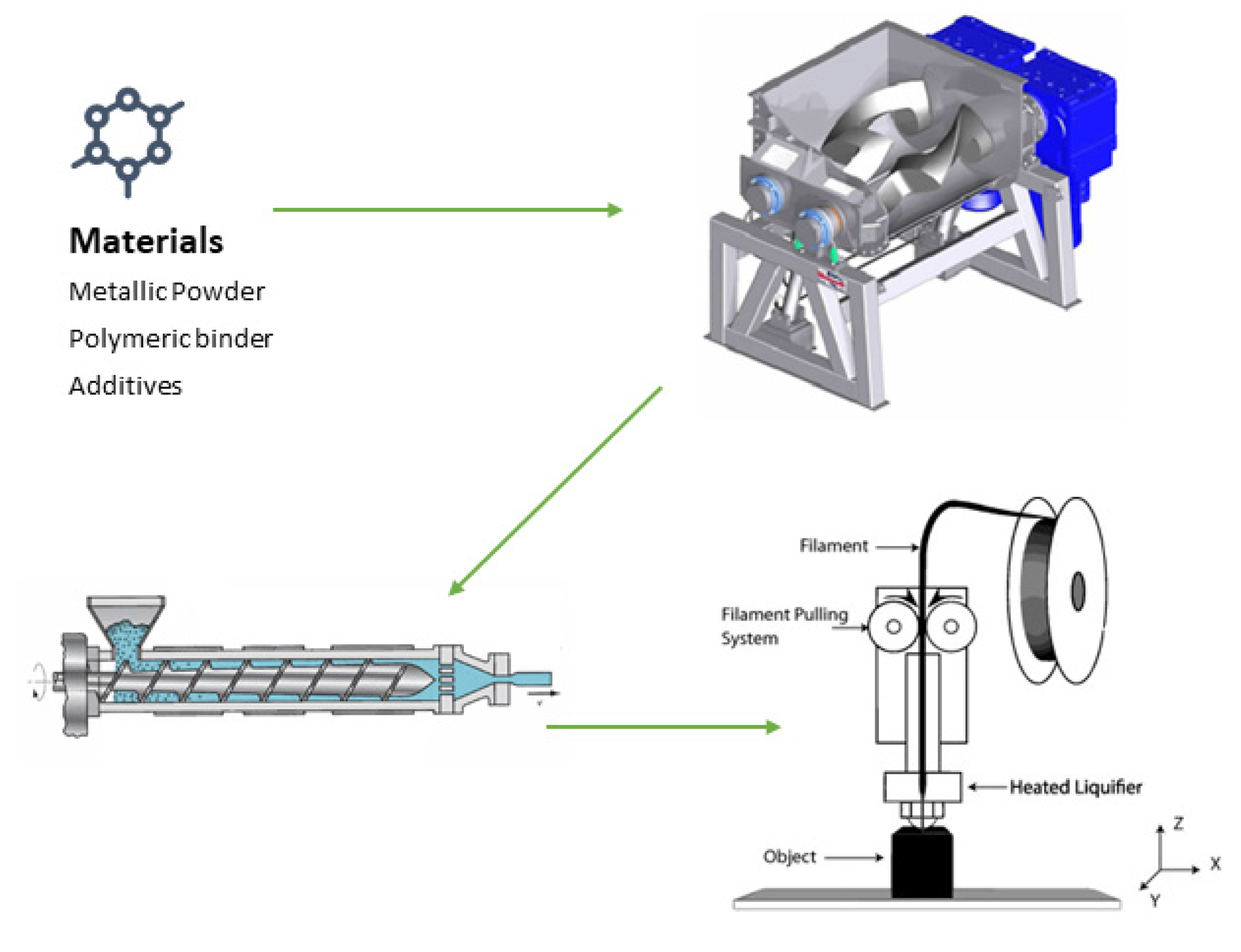
:1. Introduction
2. Materials and Methods
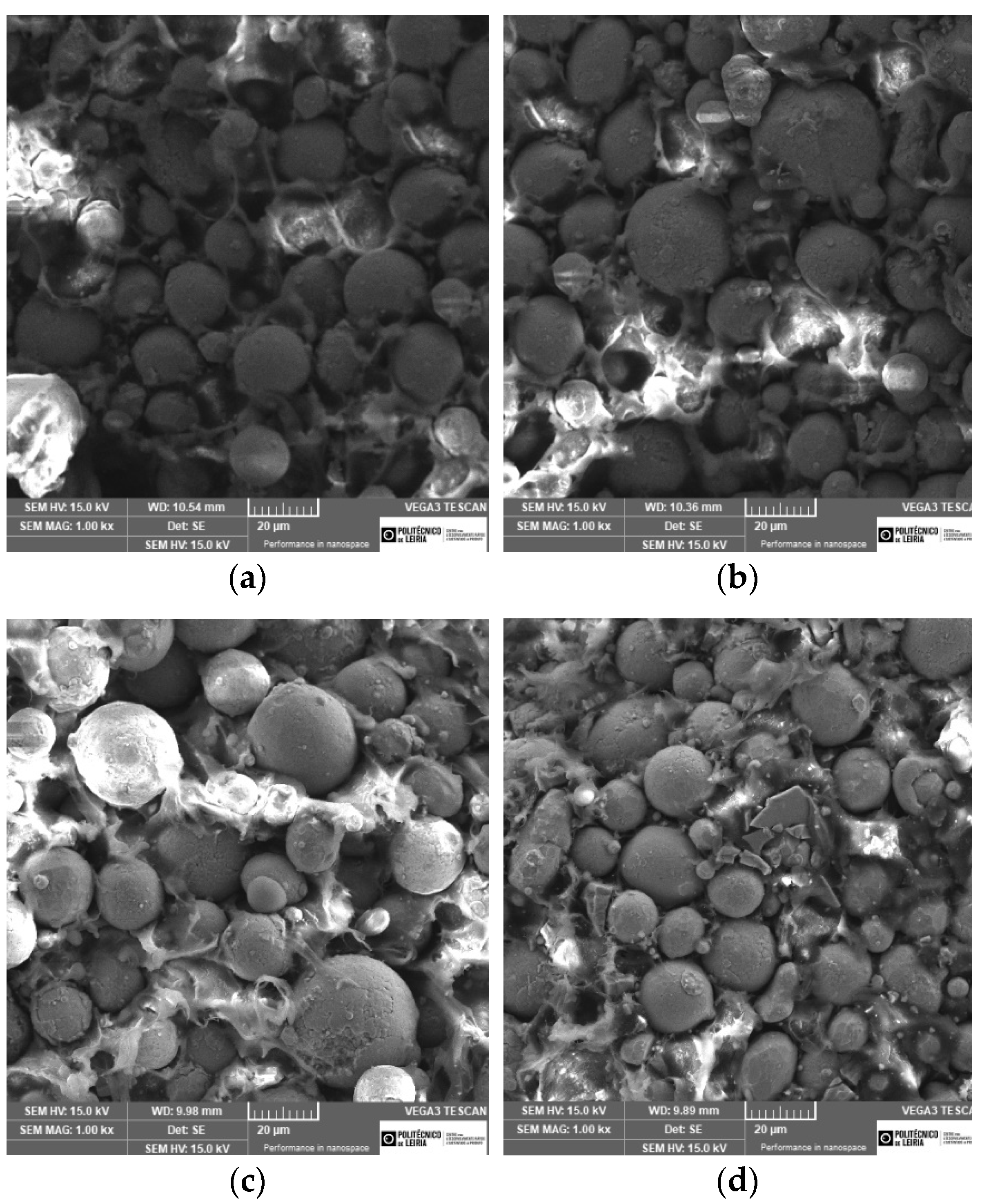
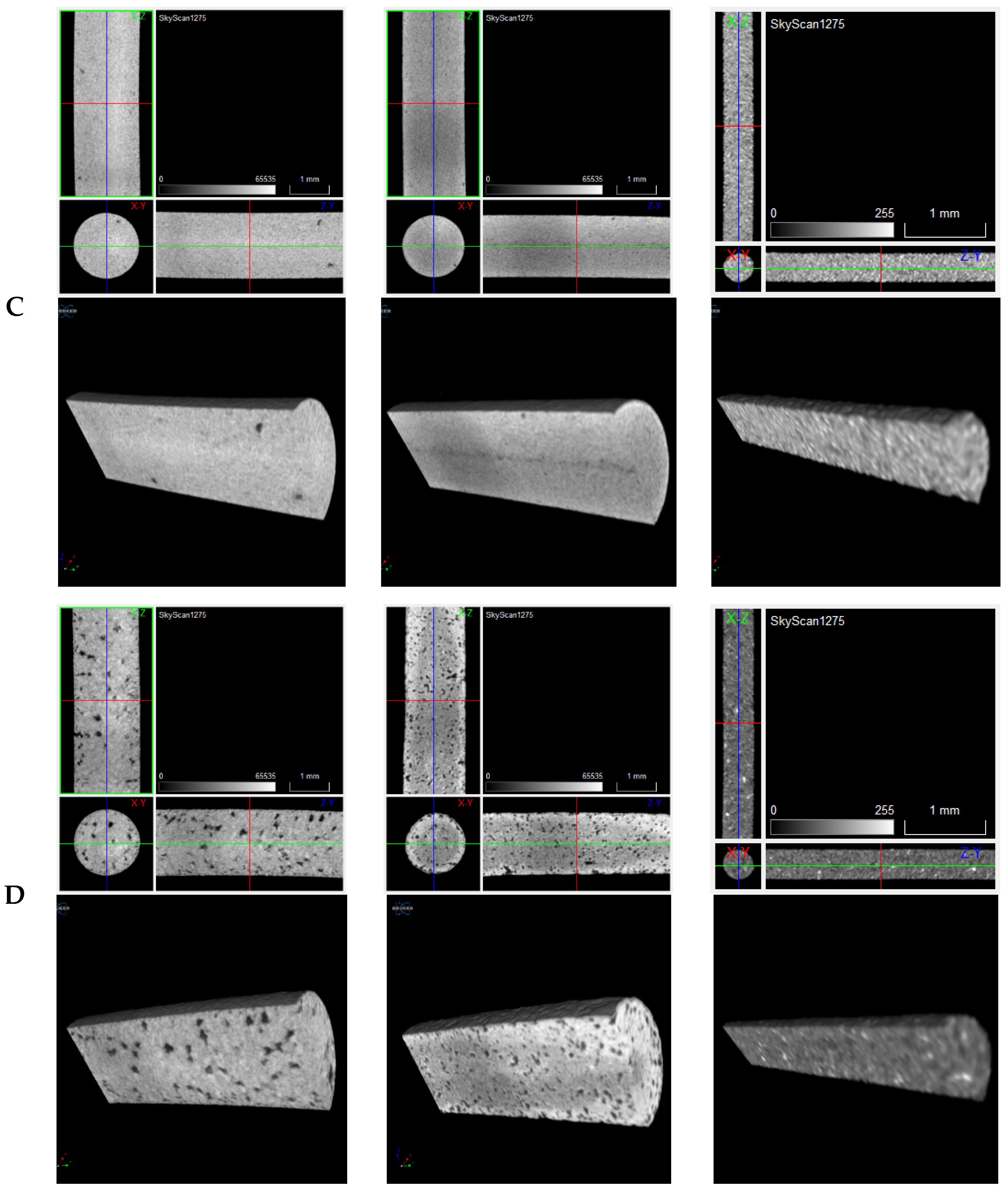
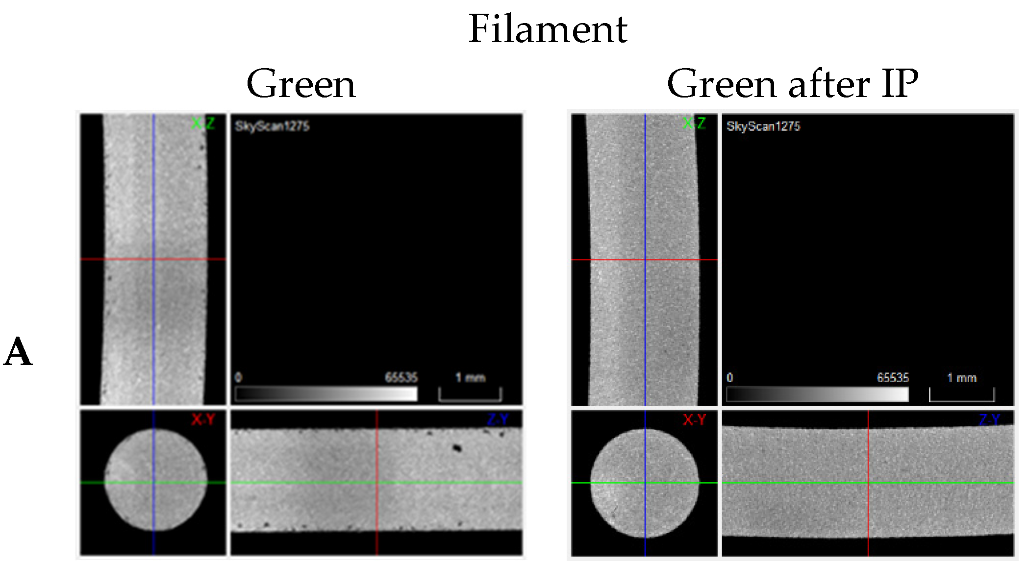
- A.
- NiTi prealloyed powder;
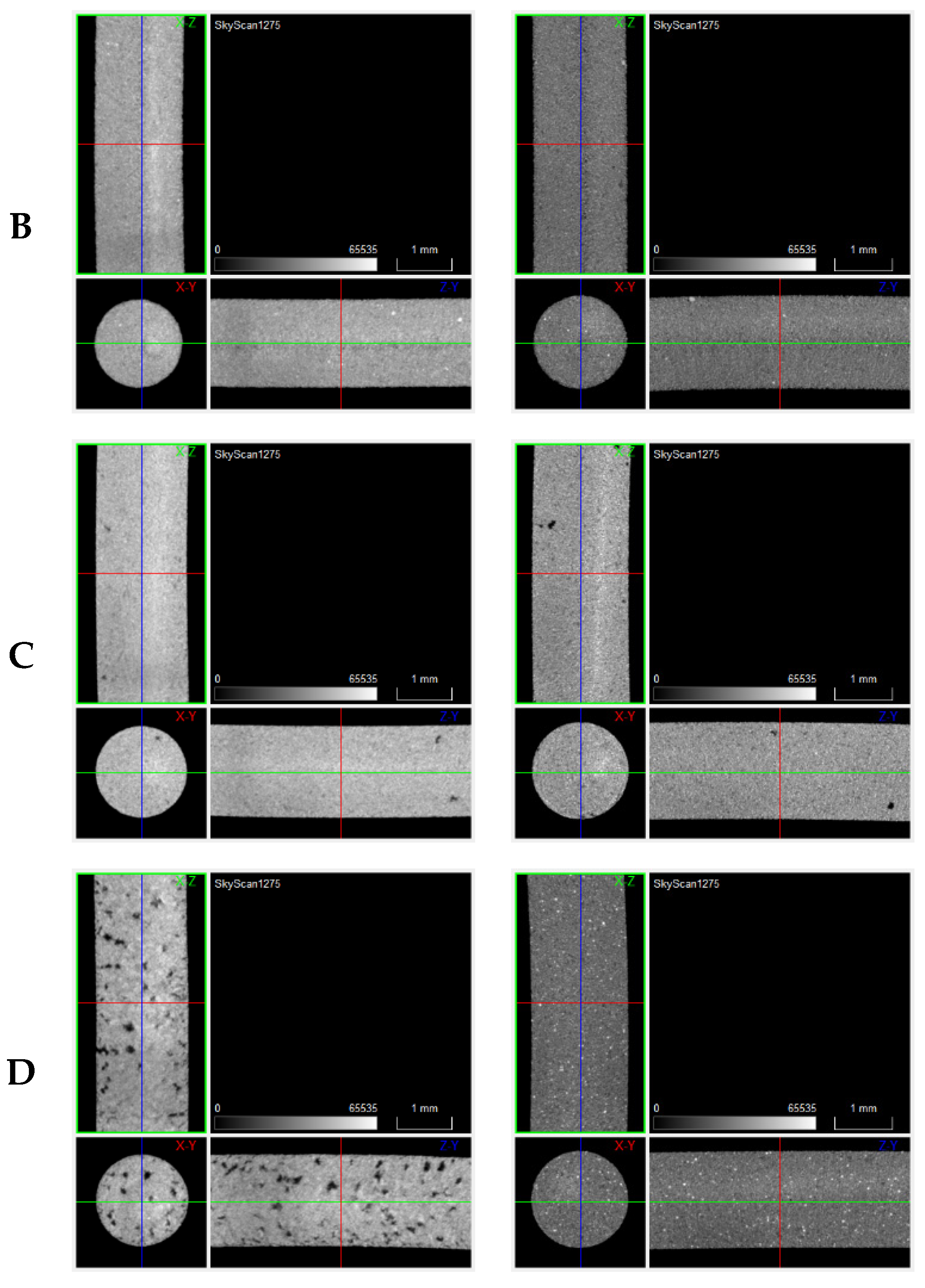
- B.
- NiTi prealloyed powder + 1 wt.% TiH2;
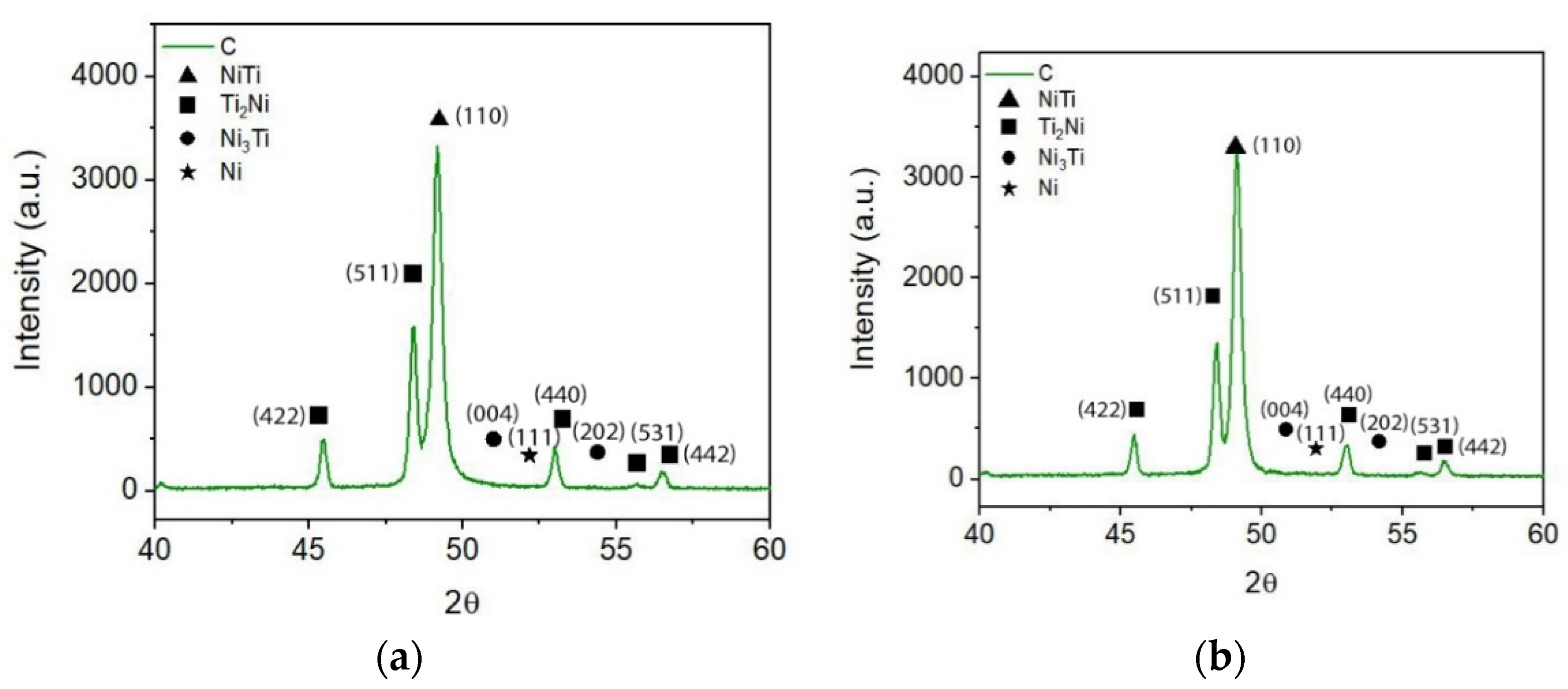
- C.
- NiTi prealloyed powder + 5 wt.% TiH2;
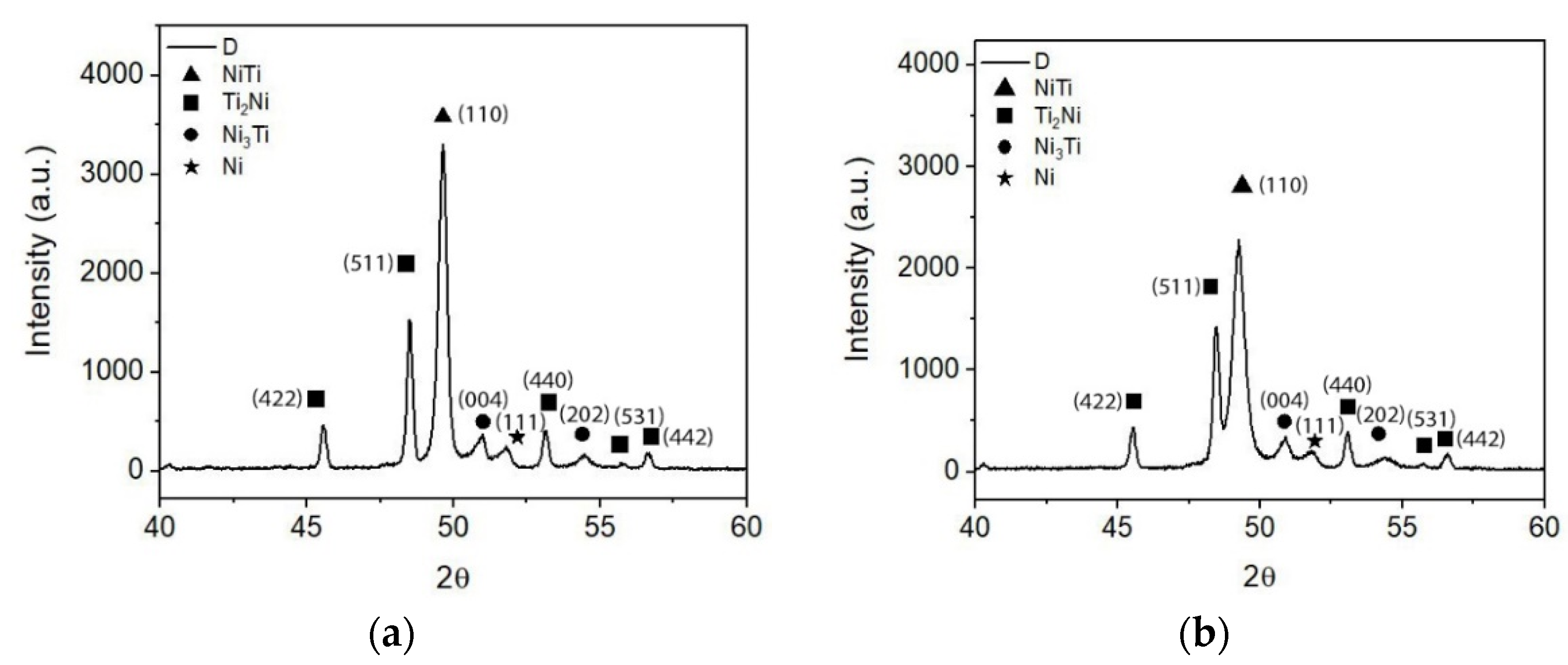
- D.
- NiTi prealloyed powder + 5 wt.% TiH2 and 6.2 wt.% Ni.
3. Results and Discussion
4. Conclusions
Author Contributions
Funding
Institutional Review Board Statement
Informed Consent Statement
Data Availability Statement
Conflicts of Interest
References
- Buehler, W.J.; Gilfrich, J.V.; Wiley, R.C. Effect of Low-Temperature Phase Changes on the Mechanical Properties of Alloys near Composition TiNi. J. Appl. Phys. 1963, 34, 1475. [Google Scholar] [CrossRef]
- Otsuka, K.; Ren, X. Physical metallurgy of Ti–Ni-based Shape Memory Alloys. Prog. Mater. Sci. 2005, 50, 511–678. [Google Scholar] [CrossRef]
- Walker, J.; Elahinia, M.; Haberland, C. An investigation of process parameters on selective laser melting of nitinol. In Proceedings of the ASME 2013 Conference on Smart Materials, Adaptive Structures and Intelligent Systems, Snowbird, UT, USA, 16–18 September 2013. [Google Scholar] [CrossRef]
- Vora, J.; Khanna, S.; Chaudhari, R.; Patel, V.K.; Paneliya, S.; Pimenov, D.Y.; Giasin, K.; Prakash, C. Machining parameter optimization and experimental investigations of nano-graphene mixed electrical discharge machining of nitinol shape memory alloy. J. Mater. Res. Technol. 2022, 19, 653–668. [Google Scholar] [CrossRef]
- Yu, Z.; Xu, Z.; Guo, Y.; Xin, R.; Liu, R.; Jiang, C.; Li, L.; Zhang, Z.; Ren, L. Study on properties of SLM-NiTi shape memory alloy under the same energy density. J. Mater. Res. Technol. 2021, 13, 241–250. [Google Scholar] [CrossRef]
- Chmielewska, A.; Wysocki, B.; Kwaśniak, P.; Kruszewski, M.J.; Michalski, B.; Zielińska, A.; Adamczyk-Cieślak, B.; Krawczyńska, A.; Buhagiar, J.; Święszkowski, W. Heat Treatment of NiTi Alloys Fabricated Using Laser Powder Bed Fusion (LPBF) from Elementally Blended Powders. Materials 2022, 15, 3304. [Google Scholar] [CrossRef]
- ISO/ASTM 52900; Additive Manufacturing—General Principles—Fundamentals and Vocabulary. ISO: Geneva, Switzerland, 2021.
- Carreira, P.; Cerejo, F.; Alves, N.; Vieira, M. In Search of the Optimal Conditions to Process Shape Memory Alloys (NiTi) Using Fused Filament Fabrication (FFF). Materials 2020, 13, 4718. [Google Scholar] [CrossRef]
- Suwanpreecha, C.; Manonukul, A. A Review on Material Extrusion Additive Manufacturing of Metal and How It Compares with Metal Injection Moulding. Metals 2022, 12, 429. [Google Scholar] [CrossRef]
- Chen, G.; Liss, K.D.; Auchterlonie, G.; Tang, H.; Cao, P. Dehydrogenation and Sintering of TiH2: An In Situ Study. Metall. Mater. Trans. A 2017, 48, 2949–2959. [Google Scholar] [CrossRef]
- Chen, G.; Cao, P.; Edmonds, N. Porous NiTi alloys produced by press-and-sinter from Ni/Ti and Ni/TiH2 mixtures. Mater. Sci. Eng. A 2013, 582, 117–125. [Google Scholar] [CrossRef]
- Bohua, D.; Yasong, Z.; Dezhi, W.; Yingrui, Z.; Chunge, X. Fabrication and Properties of Porous NiTi Alloy by Gel-Casting with TiH2 Powders. J. Mater. Eng. Perform. 2017, 26, 5118–5125. [Google Scholar] [CrossRef]
- Bhosle, V.; Baburaj, E.; Miranova, M.; Salama, K. Dehydrogenation of TiH2. Mater. Sci. Eng. A 2003, 356, 190–199. [Google Scholar] [CrossRef]
- Chen, G.; Liss, K.-D.; Cao, P. An in situ Study of NiTi Powder Sintering Using Neutron Diffraction. Metals 2015, 5, 530–546. [Google Scholar] [CrossRef] [Green Version]
- Peng, Q.; Yang, B.; Friedrich, B. Porous Titanium Parts Fabricated by Sintering of TiH2 and Ti Powder Mixtures. J. Mater. Eng. Perform. 2017, 27, 228–242. [Google Scholar] [CrossRef]
- Sun, P.; Wang, H.; Lefler, M.; Fang, Z.; Lei, T.; Fang, S.; Tian, W.; Li, H. Sintering of TiH2—A new approach for powder metallurgy titanium. In Proceedings of the World Powder Metallurgy Congress and Exhibition, Florence, Italy, 10–14 October 2010. [Google Scholar]
- Li, B.-Y.; Rong, L.-J.; Li, Y.-Y. Anisotropy of dimensional change and its corresponding improvement by addition of TiH2 during elemental powder sintering of porous NiTi alloy. Mater. Sci. Eng. A 1998, 255, 70–74. [Google Scholar] [CrossRef]
- Li, B.-Y.; Rong, L.-J.; Li, Y.-Y. The influence of addition of TiH2 in elemental powder sintering porous Ni–Ti alloys. Mater. Sci. Eng. A 2000, 281, 169–175. [Google Scholar] [CrossRef]
- Bertheville, B.; Neudenberger, M.; Bidaux, J.-E. Powder sintering and shape-memory behaviour of NiTi compacts synthesized from Ni and TiH2. Mater. Sci. Eng. A 2004, 384, 143–150. [Google Scholar] [CrossRef]
- Chen, G.; Liss, K.-D.; Cao, P. In situ observation and neutron diffraction of NiTi powder sintering. Acta Mater. 2014, 67, 32–44. [Google Scholar] [CrossRef]
- González-Gutiérrez, J.; Stringari, G.B.; Emri, I. Powder Injection Molding of Metal and Ceramic Parts. In Some Critical Issues for Injection Molding; Wang, J., Ed.; InTech: Rijeka, Croatia, 2012; pp. 65–88. [Google Scholar]
- Carneiro, O.S.; Silva, A.F.; Gomes, R. Fused deposition modeling with polypropylene. Mater. Des. 2015, 83, 768–776. [Google Scholar] [CrossRef]
- Heaney, D.F. Handbook of Metal Injection Molding; Woodhead Publishing in Materials; Woodhead Publishing: Thorston, UK, 2012. [Google Scholar]
- Barreiros, F.; Vieira, M.; Castanho, J. Fine tuning injection feedstock by nano coating SS powder. Met. Powder Rep. 2009, 64, 18–21. [Google Scholar] [CrossRef]
- Vieira, M.; Martins, A.; Barreiros, F.; Matos, M.; Castanho, J. Surface modification of stainless steel powders for microfabrication. J. Mater. Process. Technol. 2008, 201, 651–656. [Google Scholar] [CrossRef] [Green Version]
- Cerejo, F.; Gatões, D.; Vieira, M.T. Optimization of metallic powder filaments for additive manufacturing extrusion (MEX). Int. J. Adv. Manuf. Technol. 2021, 115, 2449–2464. [Google Scholar] [CrossRef]
- Dassault, S. Solidworks Student Version. 2019. Available online: https://www.3ds.com/products-services/solidworks/ (accessed on 10 May 2019).
- Ultimaker, B.V. Ultimaker Cura 4.1. 2019. Available online: https://ultimaker.com/en/products/ultimaker-cura-software (accessed on 5 March 2019).
- Bram, M.; Bitzer, M.; Buchkremer, H.P.; Stover, D. Reproducibility Study of NiTi Parts Made by Metal Injection Molding. J. Mater. Eng. Perform. 2012, 21, 2701–2712. [Google Scholar] [CrossRef]
- Bram, M.; Köhl, M.; Buchkremer, H.P.; Stöver, D. Mechanical Properties of Highly Porous NiTi Alloys. J. Mater. Eng. Perform. 2011, 20, 522–528. [Google Scholar] [CrossRef]
- Schöller, E.; Krone, L.; Bram, M.; Buchkremer, H.P.; Ståaver, D. Metal injection molding of Shape Memory Alloys using prealloyed NiTi powders. J. Mater. Sci. 2005, 40, 4231–4238. [Google Scholar] [CrossRef]
- Bidaux, J.E.; Hidalgo, A.A.; Girard, H.; Rodriguez-Arbaizar, M.; Reynard, L.; Chevallier, J.; Aeby, F.; Giachetto, J.C.; Carreño-Morelli, E. Metal Injection Moulding of Superelastic TiNi Parts. Key Eng. Mater. 2016, 704, 173–182. [Google Scholar] [CrossRef] [Green Version]
- Fang, Z.Z. (Ed.) Sintering of Advanced Materials—Fundamentals and Processes, 1st ed.; Woodhead Publishing: Cambridge, UK, 2010. [Google Scholar]
- Alnomani, S.A.; Fadhel, E.Z.; Mehatlaf, A.A. Prepare Nitinol Alloys and Improve their Hardness Using Copper as an Alloying Element. Int. J. Appl. Eng. Res. 2017, 12, 4299–4308. [Google Scholar]
- Xu, W.; Rivera-Díaz-Del-Castillo, P.; Wang, W.; Yang, K.; Bliznuk, V.; Kestens, L.; Van Der Zwaag, S. Genetic design and characterization of novel ultra-high-strength stainless steels strengthened by Ni3Ti intermetallic nanoprecipitates. Acta Mater. 2010, 58, 3582–3593. [Google Scholar] [CrossRef]
- Verdian, M.; Raeissi, K.; Salehi, M.; Sabooni, S. Characterization and corrosion behavior of NiTi–Ti2Ni–Ni3Ti multiphase intermetallics produced by vacuum sintering. Vacuum 2011, 86, 91–95. [Google Scholar] [CrossRef]
- Akbarpour, M.; Alipour, S.; Najafi, M.; Ebadzadeh, T.; Kim, H. Microstructural characterization and enhanced hardness of nanostructured Ni3Ti–NiTi (B2) intermetallic alloy produced by mechanical alloying and fast microwave-assisted sintering process. Intermetallics 2021, 131, 107119. [Google Scholar] [CrossRef]
- Feng, Y.; Du, Z.; Hu, Z. Study on the Effect of Ni Addition on the Microstructure and Properties of NiTi Alloy Coating on AISI 316 L Prepared by Laser Cladding. Materials 2021, 14, 4373. [Google Scholar] [CrossRef]
- Yoshida, M.; Shiraishi, H.; Ikk, N. Microstructure and Mechanical Properties of NiTi2-TiB Composite Fabricated by Spark Plasma Sintering. World J. Eng. Technol. 2015, 3, 84–88. [Google Scholar] [CrossRef] [Green Version]
- Wang, H.; Liu, Y. Microstructure and wear resistance of laser clad Ti5Si3/NiTi2 intermetallic composite coating on titanium alloy. Mater. Sci. Eng. A 2002, 338, 126–132. [Google Scholar] [CrossRef]
- Mokgalaka, M.; Popoola, P.; Pityana, S. In situ laser deposition of NiTi intermetallics for corrosion improvement of Ti–6Al–4V alloy. Trans. Nonferrous Met. Soc. China 2015, 25, 3315–3322. [Google Scholar] [CrossRef]


| Temperature [°C] | Holding Time [h] | Vacuum Pressure [Pa] | Processing Technology | Porosity after Sintering (%) | Post-Processing | Phases | Ref. |
|---|---|---|---|---|---|---|---|
| 950 | 1 | 1.33 × 10⁻² | Pressing | 33.9–37.6 | - | NiTi NiTi2/Ni2Ti4Ox Ni3Ti | [17,18] |
| 920 | 14 | - | Pressing | 29–34 | Aged (Ar) 500 °C (1 h) Not polished | NiTi Ni2Ti4Ox Ni4Ti3 Ni3Ti TiC0.7 N0.3 | [19] |
| HIP (Ar) 180 MPa 1050 °C (3 h) Aged (Ar) 500 °C (1 h) Not polished | NiTi Ni2Ti4Ox Ni3Ti TiC0.7 N0.3 | ||||||
| Aged (Ar) 500 °C (1 h) Polished | NiTi Ni2Ti4Ox Ni4Ti3 | ||||||
| HIP (Ar) 180 MPa 1050 °C (3 h) Aged (Ar) 500 °C (1 h) Polished | |||||||
| HIP (Ar) 180 MPa 1050 °C (3 h) Annealed (Ar) 1100 °C (1 h) Aged (Ar) 500 °C (1 h) Polished | |||||||
| 1000 | 2 | 3 × 10⁻³ | Pressing | 10–33.8 | - | NiTi NiTi2 Ni3Ti | [11] |
| 1100 | |||||||
| 1200 | |||||||
| 900 | 2 | 3 × 10⁻³ | Pressing | 19 (>900 °C) | - | Ni Ti NiTi NiTi2 Ni3Ti | [20] |
| 950 | |||||||
| 1000 | |||||||
| 1100 | |||||||
| 1200 | |||||||
| 1100 | 1000 °C 6 h vacuum | NiTi NiTi2 | |||||
| 1200 | |||||||
| 1000 | 2 | 1 × 10⁻³ | Gel Casting | 40–46 | - | NiTi NiTi2 Ni4Ti3 | [12] |
| NiTi | TiH2 | Ni | |
|---|---|---|---|
| D10 [µm] | 13.4 | 3.4 | 21.4 |
| D50 [µm] | 22.1 | 15.3 | 30.0 |
| D90 [µm] | 34.7 | 35.7 | 41.2 |
| SSA [m2 kg−1] | 293.4 | 750.2 | 207.7 |
| A | B | C | D | |
|---|---|---|---|---|
| Steady state torque [Nm] | 4.2 | 4.0 | 4.6 | 4.8 |
| A | B | C | D | |
|---|---|---|---|---|
| Young modulus [GPa] | 2.6 ± 0.11 | 2.8 ± 0.15 | 2.7 ± 0.14 | 2.5 ± 0.28 |
| Tests | A | B | C | D |
|---|---|---|---|---|
| 3-point bending | 23 | 29 | 28 | 45 |
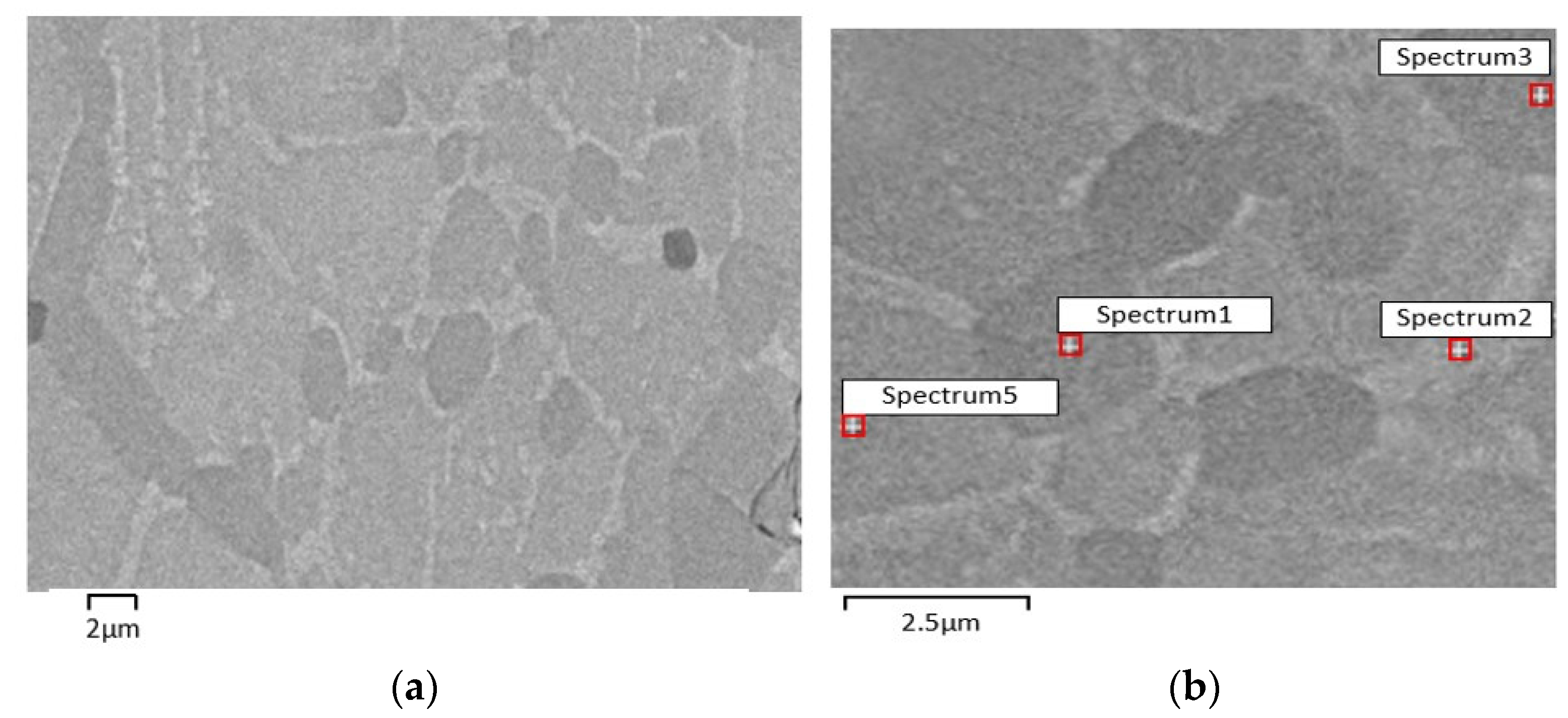
| Phase Composition (EDS) | |||
|---|---|---|---|
| S1 | S2 | S3 | S5 |
| NiTi2 | Ni3Ti | NiTi2 | NiTi |
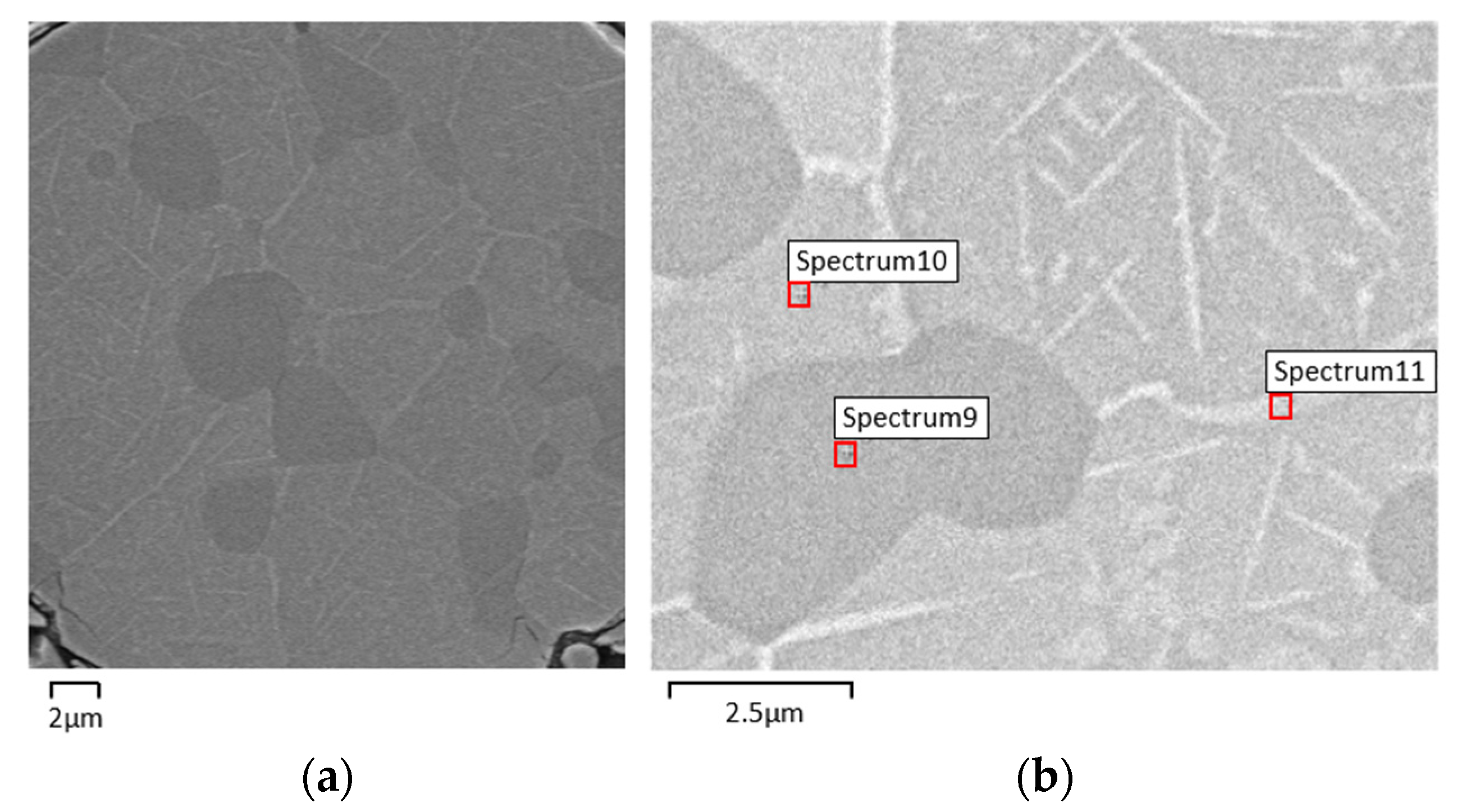
| Phase Composition (EDS) | ||
|---|---|---|
| S9 | S10 | S11 |
| NiTi2 | NiTi | Ni3Ti |
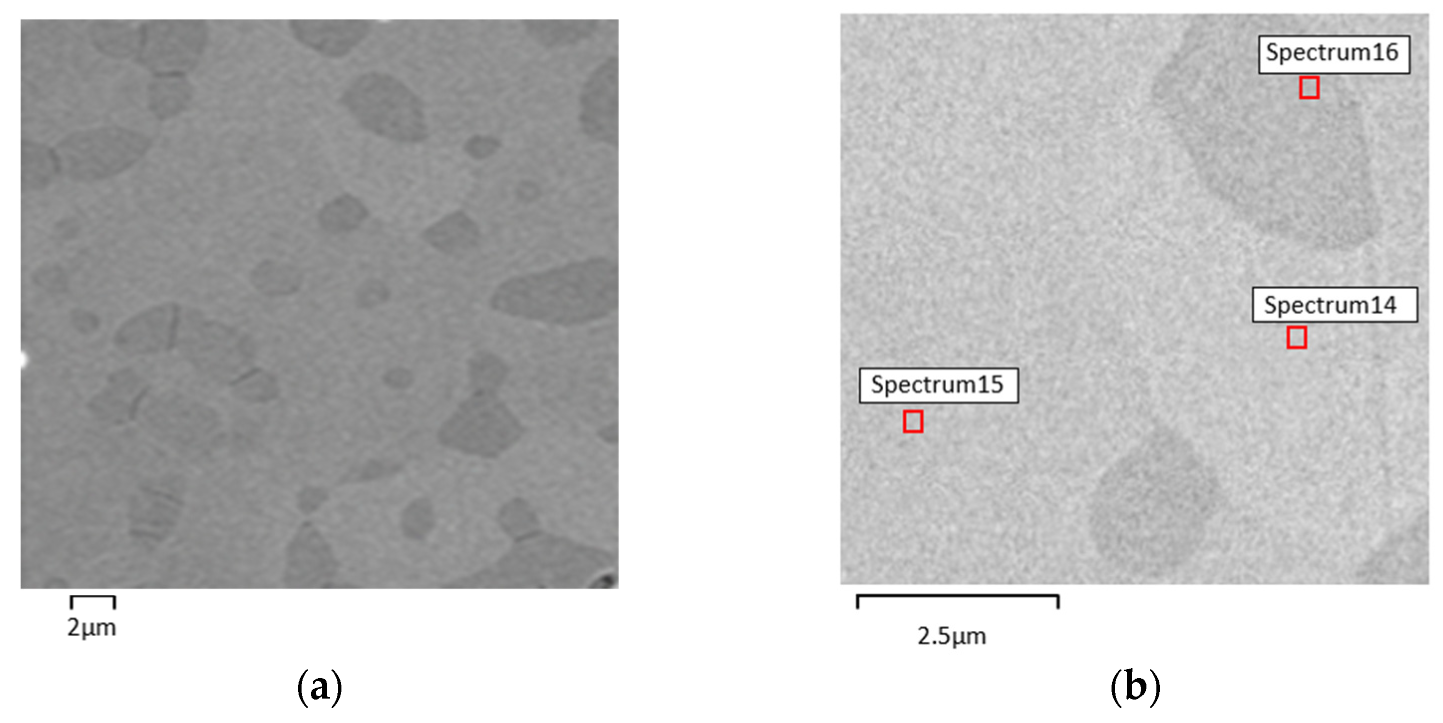
| Phase Composition (EDS) | ||
|---|---|---|
| S14 | S15 | S16 |
| NiTi | NiTi | NiTi2 |
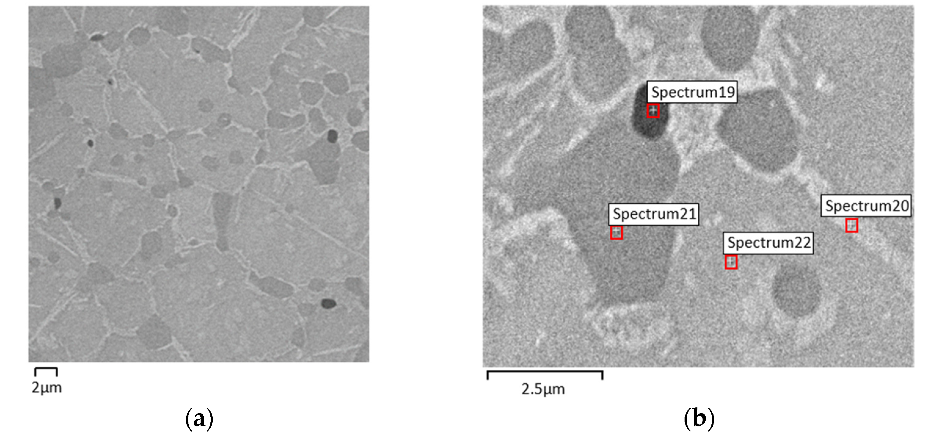
| Phase Composition (EDS) | |||
|---|---|---|---|
| S19 | S20 | S21 | S22 |
| Ti | Ni3Ti | NiTi2 | NiTi |
| A | B | C | D | |
|---|---|---|---|---|
| Hardness [HV0.01] | 887 ± 58 | 773 ± 68 | 715 ± 39 | 677 ± 59 |
Publisher’s Note: MDPI stays neutral with regard to jurisdictional claims in published maps and institutional affiliations. |
© 2022 by the authors. Licensee MDPI, Basel, Switzerland. This article is an open access article distributed under the terms and conditions of the Creative Commons Attribution (CC BY) license (https://creativecommons.org/licenses/by/4.0/).
Share and Cite
Carreira, P.; Gatões, D.; Alves, N.; Ramos, A.S.; Vieira, M.T. Searching New Solutions for NiTi Sensors through Indirect Additive Manufacturing. Materials 2022, 15, 5007. https://doi.org/10.3390/ma15145007
Carreira P, Gatões D, Alves N, Ramos AS, Vieira MT. Searching New Solutions for NiTi Sensors through Indirect Additive Manufacturing. Materials. 2022; 15(14):5007. https://doi.org/10.3390/ma15145007
Chicago/Turabian StyleCarreira, Pedro, Daniel Gatões, Nuno Alves, Ana Sofia Ramos, and Maria Teresa Vieira. 2022. "Searching New Solutions for NiTi Sensors through Indirect Additive Manufacturing" Materials 15, no. 14: 5007. https://doi.org/10.3390/ma15145007
APA StyleCarreira, P., Gatões, D., Alves, N., Ramos, A. S., & Vieira, M. T. (2022). Searching New Solutions for NiTi Sensors through Indirect Additive Manufacturing. Materials, 15(14), 5007. https://doi.org/10.3390/ma15145007