
Geotechnical Evaluation of Loess Modifications as the Sustainable Compacted Soil Liner Material in Solid Waste Landfill

 , ,
, ,  ,
,
Abstract
:1. Introduction
2. Materials and Methods
2.1. Materials
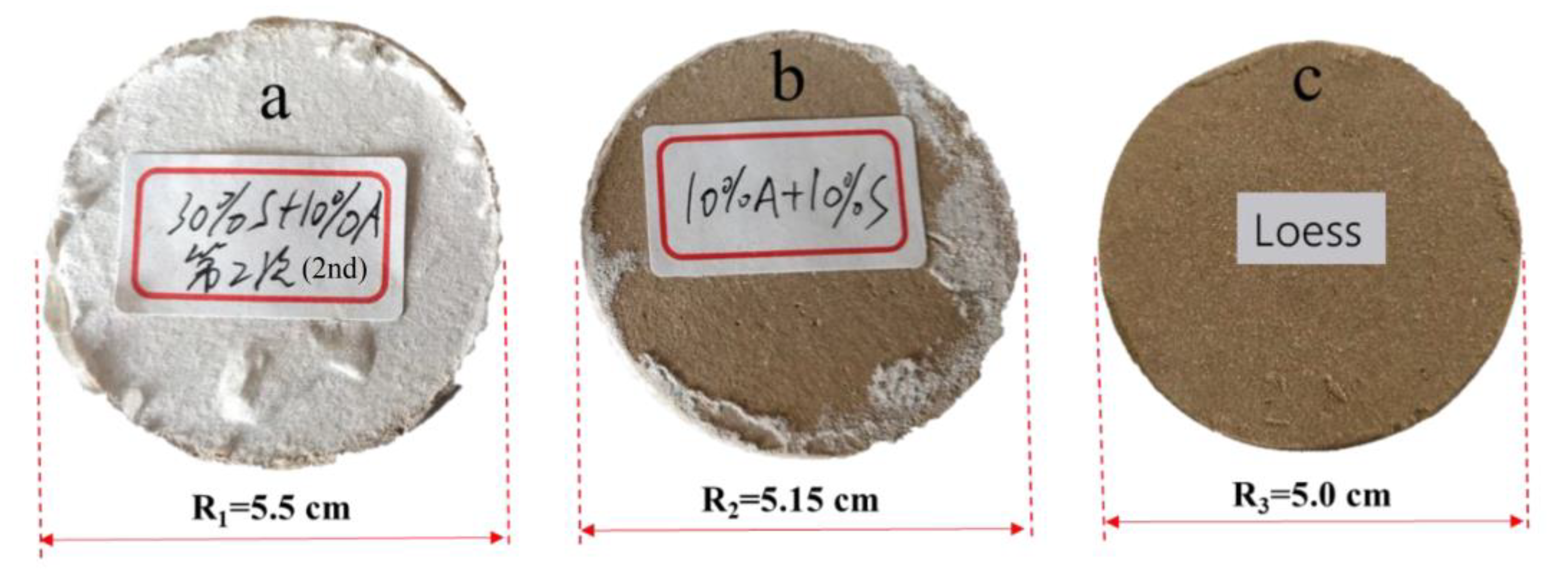
2.2. Loess Modification Mixtures
2.3. Testing Methods
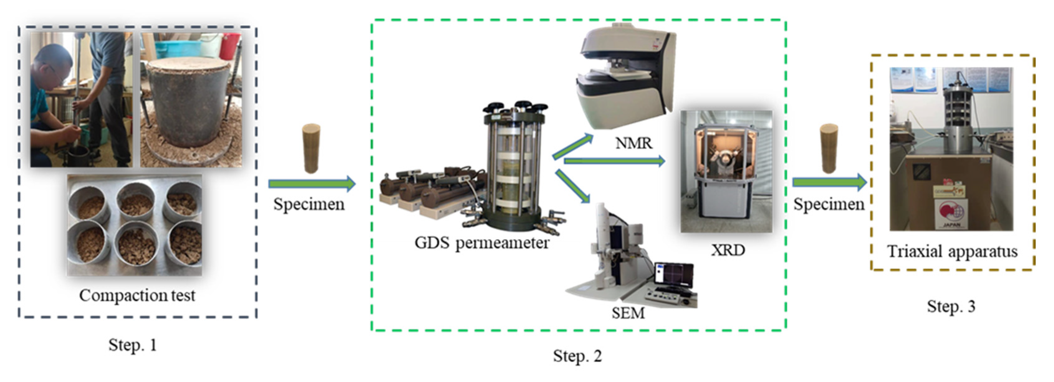
2.3.1. Compaction Test
2.3.2. Permeation Test
2.3.3. NMR, SEM, and XRD Test
2.3.4. Shear Strength Test
3. Results
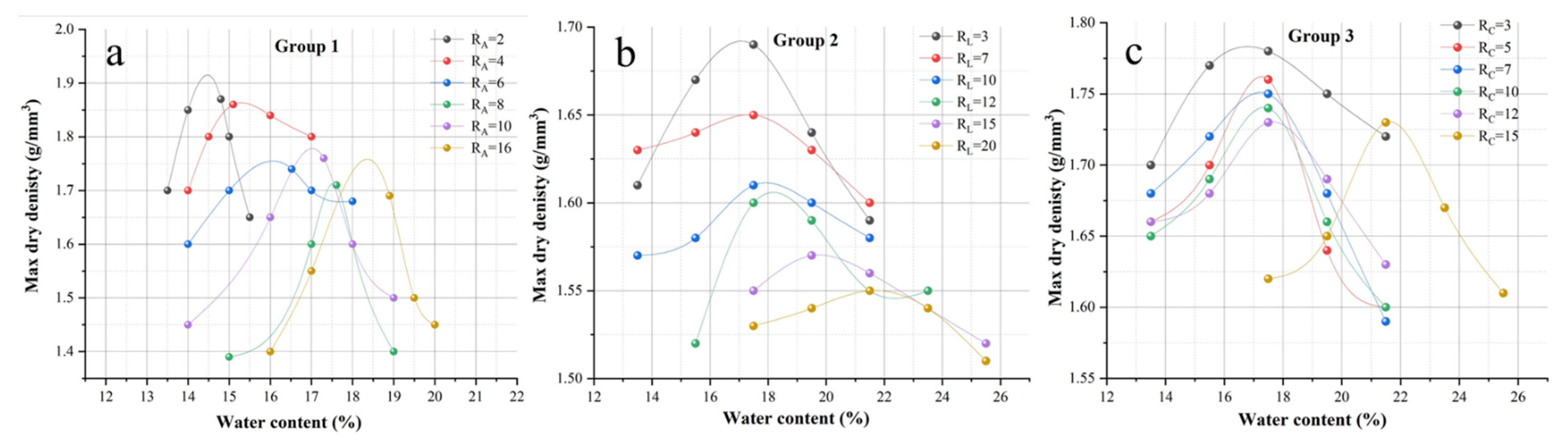
3.1. Compaction Test
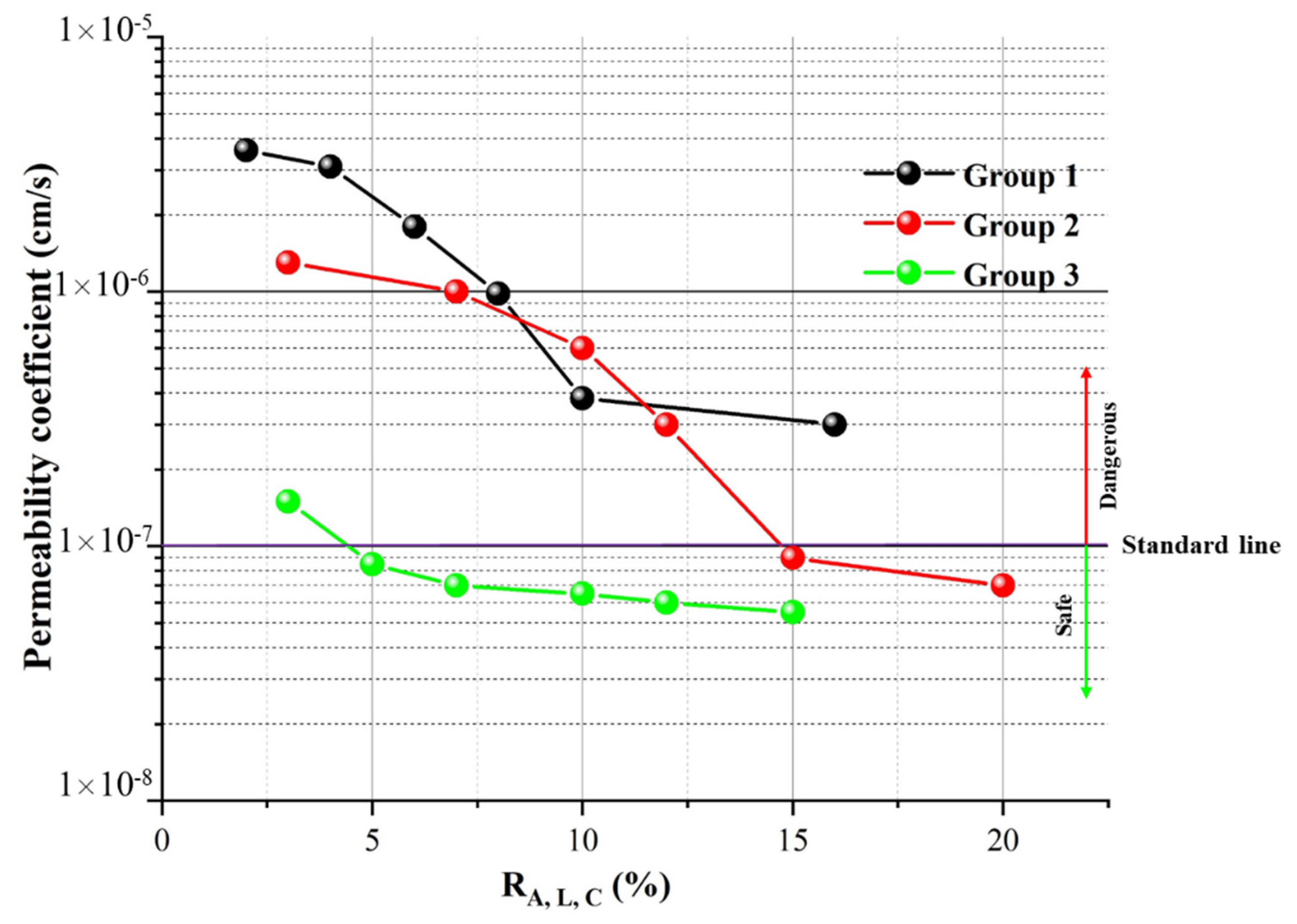
3.2. The Permeability Coefficient
3.3. NMR Test
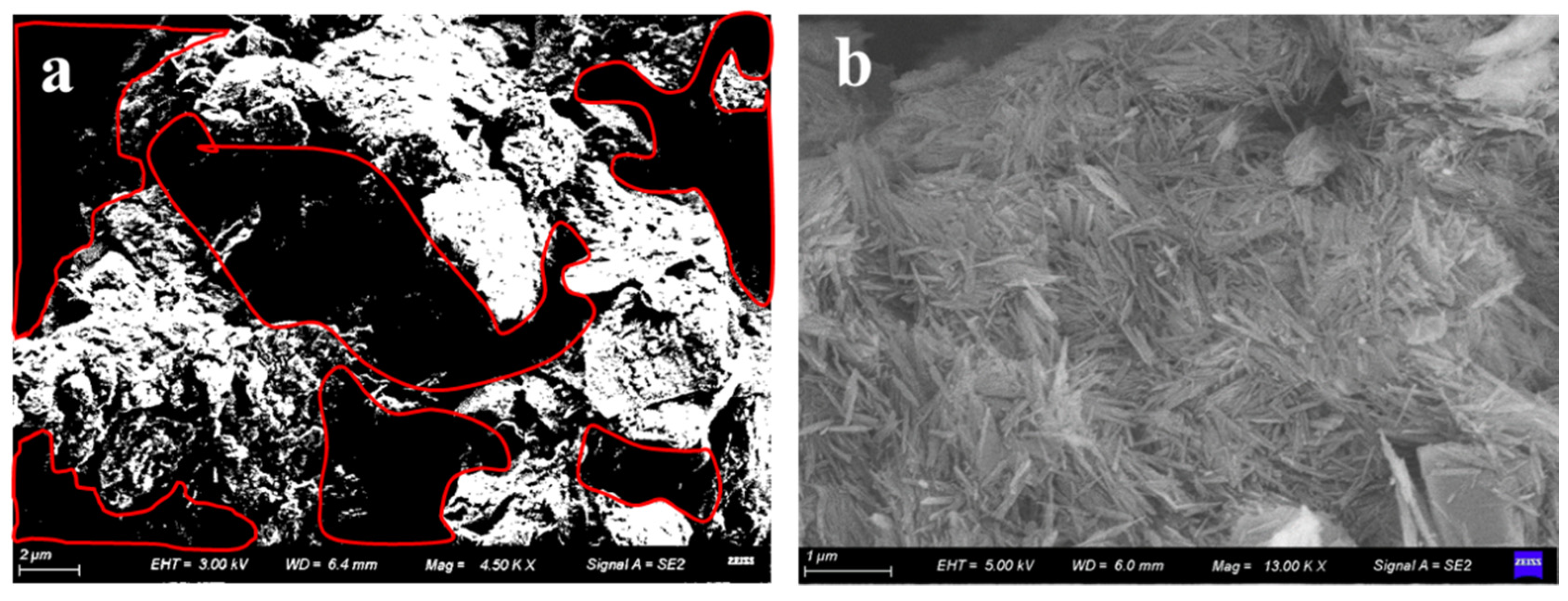
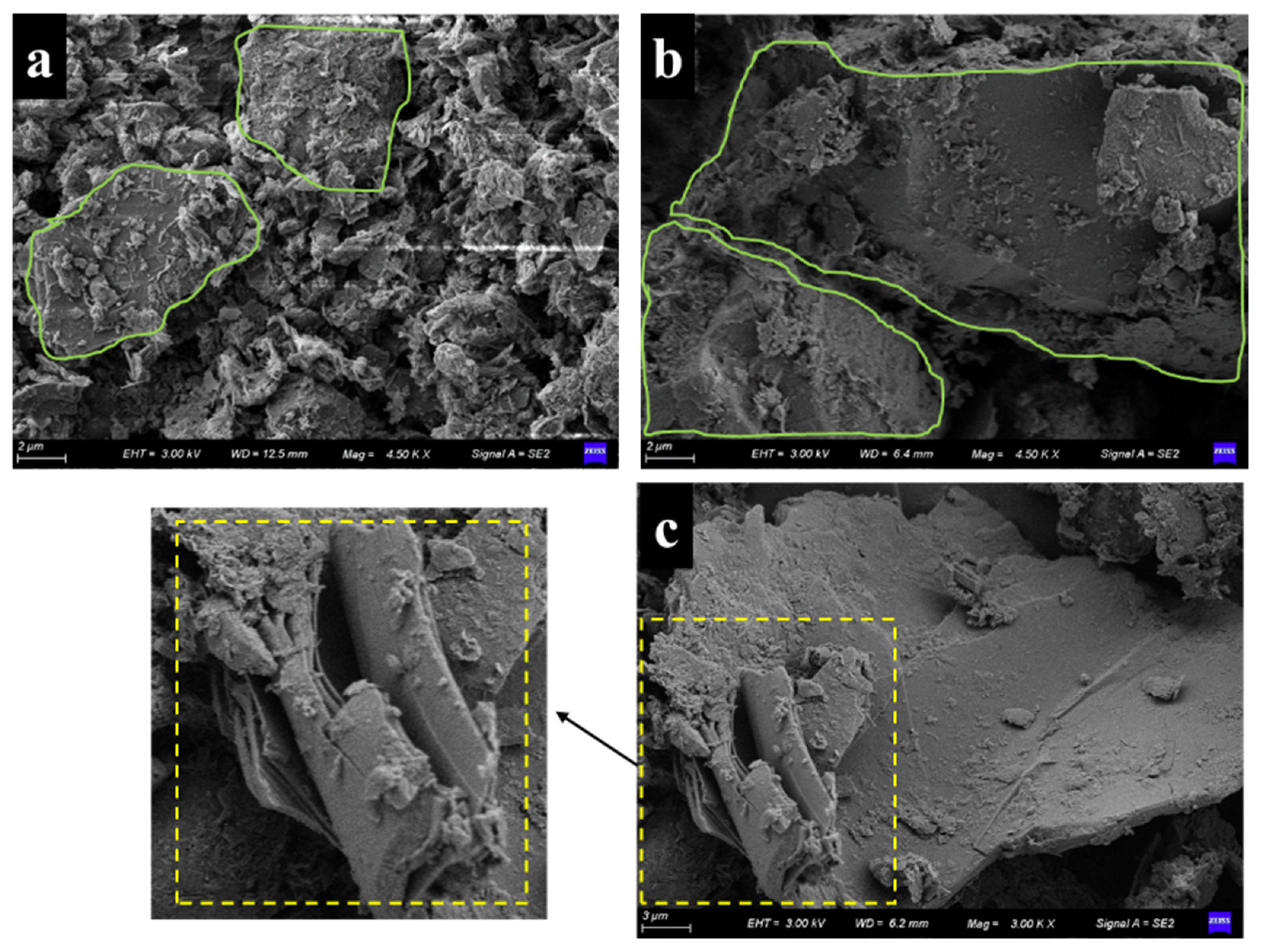
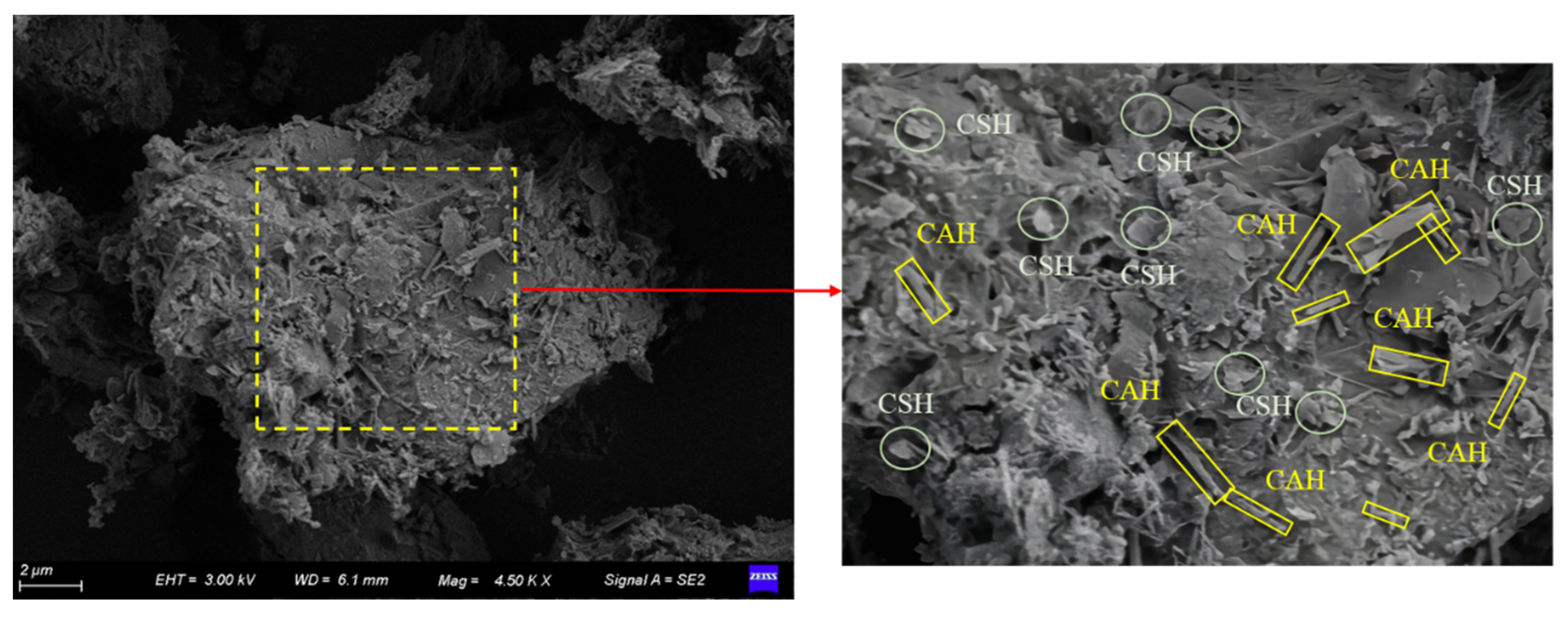
3.4. SEM Test
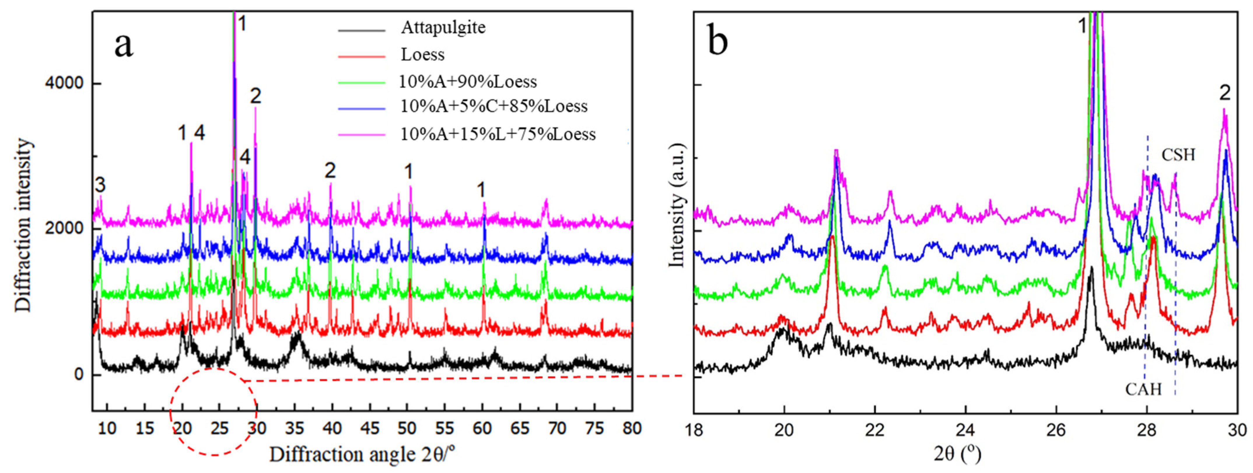
3.5. XRD Test
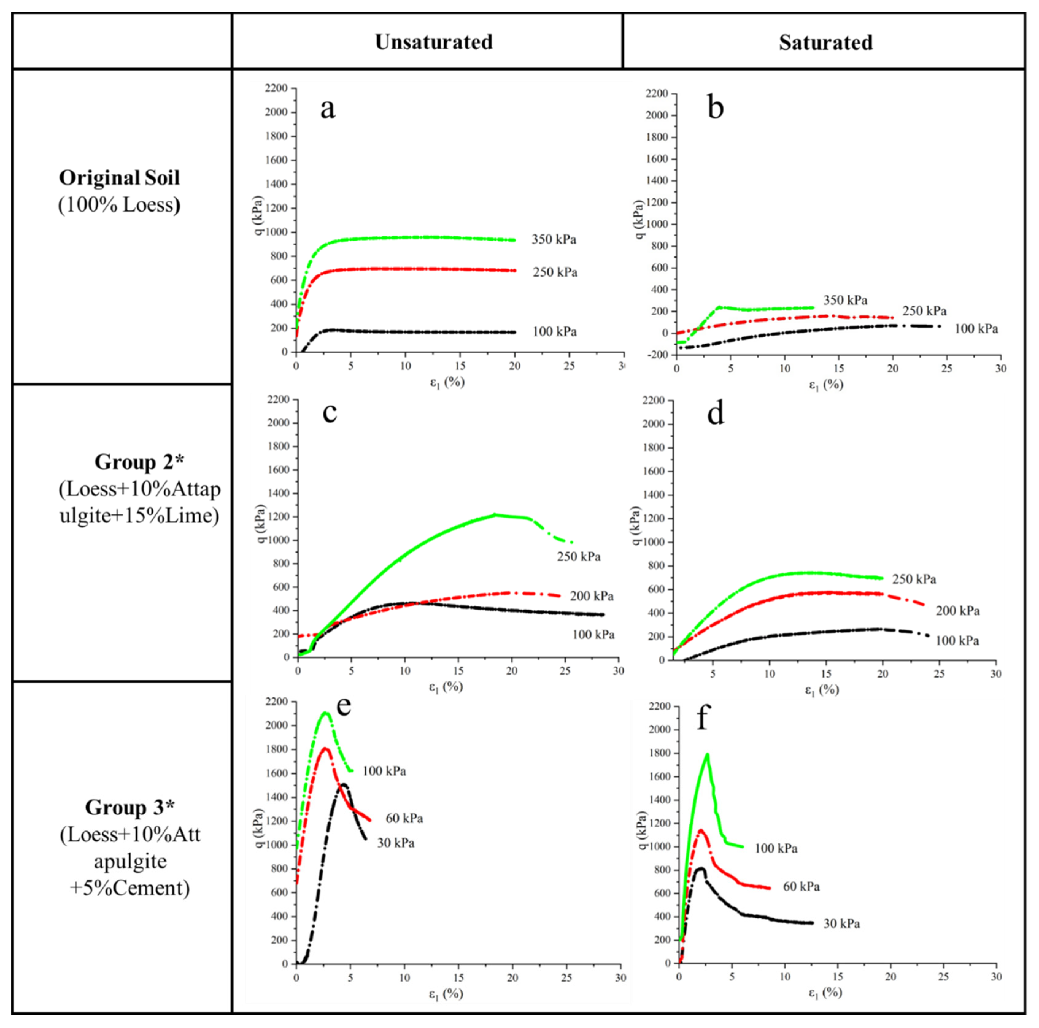
3.6. Shear Strength Test
4. Conclusions
- 1.
- Attapulgite can significantly reduce the permeability coefficient of loess. The permeability coefficient dropped from 3.0 × 10⁻⁶ cm/s to 4.2 × 10⁻⁷ cm/s. However, the effect is not obvious when the content of attapulgite exceeds 10%. The permeability coefficient of modified loess can be further reduced by adding 15% lime or 5% cement based on 10% attapulgite content. The permeability coefficient can be reduced to 4.5 × 10⁻⁸ cm/s and 9.2 × 10⁻⁸ cm/s, respectively, which can meet the impermeability requirements of the landfill site. Through microscopic test and composition analysis, it is found that the anti-seepage mechanism of the loess modified by attapulgite is that attapulgite fills the pores between loess particles. The acicular attapulgite combines with loess to form a flake integral structure, thus reducing the permeability coefficient. When lime and cement are added to loess, calcium aluminate hydrate is created, which binds soil particles together to form a block structure with better overall integrity, reducing the permeability coefficient of the modified soil, among which attapulgite and cement modified loess have the best anti-seepage effect.
- 2.
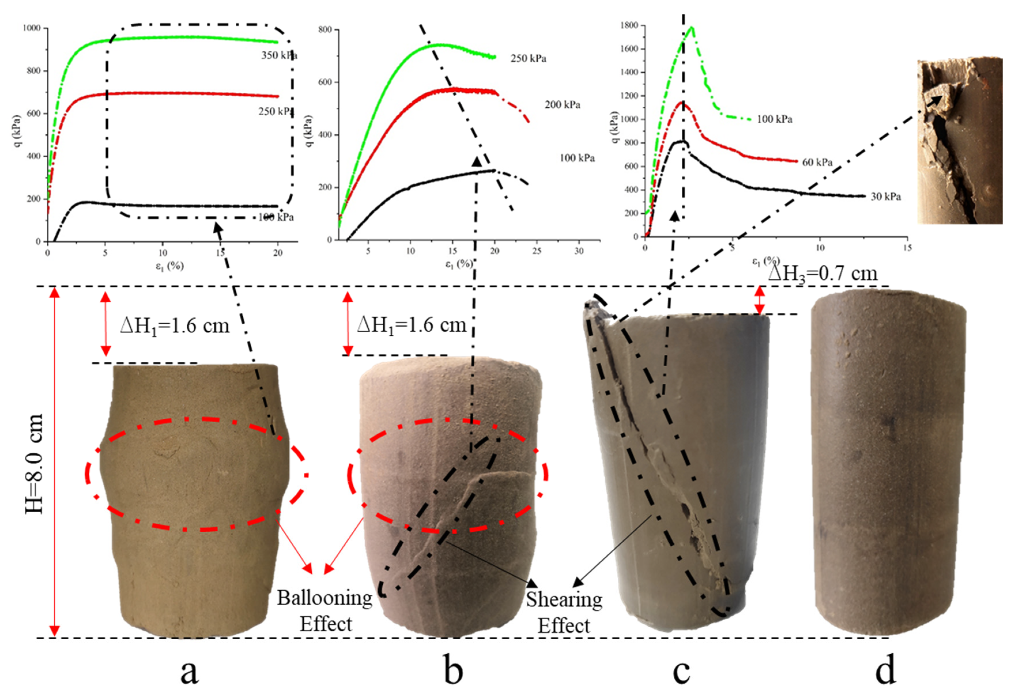
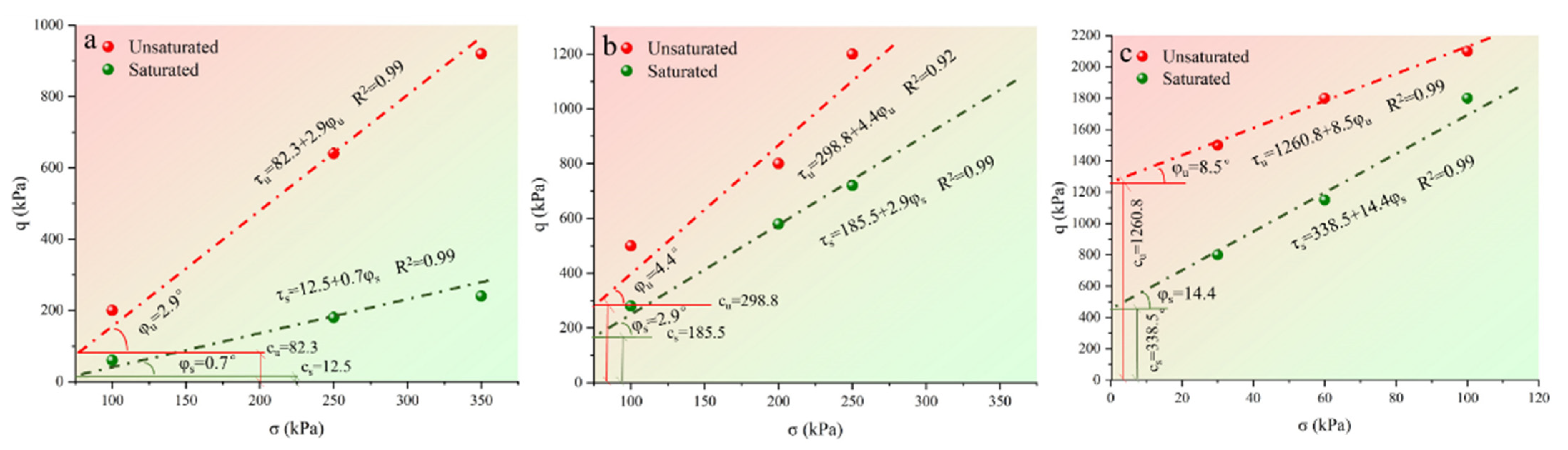
- According to the static triaxial shear test, the shear strength of the loess modified with attapulgite-lime and the loess modified with attapulgite-cement is greatly improved compared with the pure loess cohesion. The friction angle of the specimen is also increased. The shear strength of the same specimen under unsaturated conditions is more significant than that under saturated conditions. Swelling failure mainly occurred in the loess specimens with low shear strength, and shear failure happened with increased shear strength.
5. Possible Directions for Future Studies
Author Contributions
Funding
Institutional Review Board Statement
Informed Consent Statement
Data Availability Statement
Acknowledgments
Conflicts of Interest
References
- Peng, L.J.; Gu, M.; Peng, Z. Study on the Optimized Mode of Waste Governance with Sustainable Urban Development—Case from China’s Urban Waste Classified Collection. Sustainability 2020, 12, 3706. [Google Scholar] [CrossRef]
- Li, Y.; Cen, H.; Chiu, Y.-h.; Lin, T.-Y. Waste landfill plant and waste disposal plant efficiencies in China. J. Mater. Cycles Waste Manag. 2021, 23, 922–936. [Google Scholar] [CrossRef]
- Liu, J.; Li, Y.; Xiao, B.; Jiao, J. Coupling Fuzzy Multi-Criteria Decision-Making and Clustering Algorithm for MSW Landfill Site Selection (Case Study: Lanzhou, China). ISPRS Int. J. Geo Inf. 2021, 10, 403. [Google Scholar] [CrossRef]
- Guang, W.X.; Zhen, L.; Nan, K.; Teng, G.Z. Numerical Analysis of Expansive Soil Slope Reinforced by Improved Soil Replacement Method and Lime Pile Method. Yellow River 2019, 5, 129–134. [Google Scholar]
- Liu, X.; Lin, C.; Zhang, X.; Kong, Q. Model Test Study on Seepage of Jointed Loess. Soil Mech. Found. Eng. 2020, 57, 316–321. [Google Scholar] [CrossRef]
- Gassner, F. Development and management of geomembrane liner hippos. Geotex Tiles Geomembr. 2017, 45, 702–706. [Google Scholar] [CrossRef]
- Liu, Y.S.; Bai, Q.Z.; Nie, Y.F. Properties of bentonite enhanced loess and laterite. Chin. J. Chem. Eng. 2004, 12, 37–41. [Google Scholar]
- Zhao, T.Y.; Zhang, H.Y.; Yang, G.S.; Wu, J.R.; Liu, J.S. Influence of penetrative conditions on permeability modified loess soil by bentonite. Hydrogeol. Eng. Geol. 2010, 37, 108–112. [Google Scholar]
- Qi, T.; Ansheng, F.; Xinhai, L.; Yulin, L.; Yi, Z. The Development Status and Tendency of Nonmetallic Mineral Resources in China. Conserv. Util. Miner. Resour. 2015, 35, 52–56. [Google Scholar] [CrossRef]
- Ghadakpour, M.; Choobbasti, A.J.; Kutanaei, S.S. Experimental study of the impact of cement treatment on the shear behavior of loess and clay. Arab. J. Geosci. 2020, 13, 184. [Google Scholar] [CrossRef]
- Kozubal, J.; Steshenko, D. The complex compaction method of an unstable loess substrate. Arab. J. Geosci. 2014, 8, 6189–6198. [Google Scholar] [CrossRef]
- Kozubal, J.; Steshenko, D.; Galay, B. The improvement of loess substrates with a new type of soil column with a reliability assessment. Road Mater. Pavement Des. 2014, 15, 856–871. [Google Scholar] [CrossRef]
- Kanty, P.; Rybak, J.; Stefaniuk, D. Some Remarks on Practical Aspects of Laboratory Testing of Deep Soil Mixing Composites Achieved in Organic Soils. IOP Conf. Ser. Mater. Sci. Eng. 2017, 245, 022018. [Google Scholar] [CrossRef] [Green Version]
- Zhang, Z.; Matlan, S.J.; Zhang, L.; Wang, H. Experimental and Numerical Analysis Study on Loess-Lime Structures Used for Lateral Antiseepage in Deep Collapsible Ground Embankment. Adv. Civ. Eng. 2021, 2021, 9964852. [Google Scholar] [CrossRef]
- Zhang, H.; Zhao, T.; Wu, J.; Yan, G.; Feng, L. Labor atory measurement and prediction of the permeability of bentonite-modified loess as a landfill liner. Rock Soil Mech. 2011, 32, 1963–1974. [Google Scholar] [CrossRef]
- Niu, Y.; Wang, X.; Zheng, J.; Jiang, D.; Liu, D.; Jiang, P. Experimental research on the anti-seepage effect of new embankment structure of lateral-constraint and seepage control. Rock Soil Mech. 2015, 36, 252–258. [Google Scholar]
- Du, L.; Wang, P.; Li, X.; Tan, Z. Effect of Attapulgite colloids on uranium migration in quartz column. Appl. Geochem. 2018, 100, 363–370. [Google Scholar] [CrossRef]
- Wang, Y.; Feng, Y.; Jiang, J.; Yao, J. Designing of Recyclable Palygorskite for Wastewater Treatments: A Review. ACS Sustain. Chem. Eng. 2018, 7, 1855–1869. [Google Scholar] [CrossRef]
- Zhang, Z.; Gui, W.; Wei, J.; Cui, Y.; Li, P.; Jia, Z.; Kong, P. Functionalized Attapulgite for the Adsorption of Methylene Blue: Synthesis, Characterization, and Adsorption Mechanism. ACS Omega 2021, 6, 19586–19595. [Google Scholar] [CrossRef]
- Song, J.; Ma, J.; Li, F.; Chai, L.; Chen, W.; Dong, S.; Li, X. Study on Fractal Characteristics of Mineral Particles in Undisturbed Loess and Lime-Treated Loess. Materials 2021, 14, 6549. [Google Scholar] [CrossRef]
- Wu, Z.; Deng, Y.; Liu, S.; Liu, Q.; Chen, Y.; Zha, F. Strength and microstructure evolution of compacted soils modified by admixtures of cement and metakaolin. Appl. Clay 2016, 127–128. [Google Scholar] [CrossRef] [Green Version]
- Deng, Y.; Yue, X.; Liu, S.; Chen, Y.; Zhang, D. Hydraulic conductivity of cement-stabilized marine clay with metakaolin and its correlation with pore size distribution. Eng. Geol. 2015, 193, 146–152. [Google Scholar] [CrossRef]
- Pakbaz, M.S.; Farzi, M. Comparison of the effect of mixing methods (dry vs. wet) on mechanical and hydraulic properties of treated soil with cement or lime. Appl. Clay 2015, 105–106, 156–169. [Google Scholar] [CrossRef]
- Rajabi, A.M.; Zahra, H. An experimental study on the influence of metakaolin on mechanical properties of clayey sand. Bull. Eng. Geol. Environ. 2021, 8, 7921–7932. [Google Scholar] [CrossRef]
- Qian, X.; Li, Z. The relationships between stress and strain for high-performance concrete with metakaolin. Cem. Concr. Res. 2001, 31, 1607–1611. [Google Scholar] [CrossRef]


| Particle Size (mm) | Loess (%) | Attapulgite (%) |
|---|---|---|
| >1.1 | 0.37 | 0 |
| 1.1–0.25 | 19.43 | 0 |
| 0.25–0.075 | 23.8 | 0 |
| 0.075–0.05 | 9.9 | 4.6 |
| 0.05–0.01 | 28.4 | 67.72 |
| 0.01–0.005 | 9.1 | 22.7 |
| <0.005 | 9.0 | 5.0 |
| Liquid Limit, LL | 28.7% | - |
| Plastic Limit, PL | 14.9% | - |
| Plastic Index, PI | 13.8 | - |
| Types of Chemical | Loess (%) | Attapulgite (%) |
|---|---|---|
| Strontium oxide, SrO | 0.07 | - |
| Iron (ii) oxide, Fe2O3 | 6.6 | 5.5 |
| Silicon dioxide, SiO2 | 53.0 | 63.3 |
| Aluminum oxide, Al2O3 | 15.6 | 11.6 |
| Calcium oxide, CaO | 1.95 | 1.14 |
| Titanium dioxide, TiO2 | 0.93 | 0.84 |
| Potassium oxide, K2O | 3.16 | 1.07 |
| Manganese oxide, MnO | 0.13 | 15.58 |
| Sodium oxide, Na2O | 2.16 | 0.15 |
| Magnesium oxide, MgO | 12.8 | 11.35 |
| Phosphorus pentoxide, P2O5 | - | 0.4 |
| Initial Jelling Time (min) | Final Setting Time (min) | 3 Days | 28 Days | ||
|---|---|---|---|---|---|
| Flexural Strength | Compressive Strength | Flexural Strength | Compressive Strength | ||
| >45 | <600 | 2.5 MPa | 10 MPa | 5.5 MPa | 32.5 MPa |
| Group 1 | Group 2 | Group 3 | |||||
|---|---|---|---|---|---|---|---|
| Loess (%) | Attapulgite (%) | Loess (%) | Attapulgite (%) | Lime (%) | Loess (%) | Attapulgite (%) | Cement (%) |
| 98 | 2 | 87 | 10 | 3 | 87 | 10 | 3 |
| 96 | 4 | 83 | 10 | 7 | 85 | 10 | 5 |
| 94 | 6 | 80 | 10 | 10 | 83 | 10 | 7 |
| 92 | 8 | 78 | 10 | 12 | 80 | 10 | 10 |
| 90 | 10 | 75 | 10 | 15 | 78 | 10 | 12 |
| 84 | 16 | 70 | 10 | 20 | 75 | 10 | 15 |
| Percentage of Attapulgite (%) | Parameter | 2 | 4 | 6 | 8 | 10 | 16 |
|---|---|---|---|---|---|---|---|
| Group 1 (Loess + %Attapulgite) | OMC 1 (%) | 13.9 | 13.23 | 16.52 | 17.01 | 17.3 | 18.85 |
| MDD 2 (g/cm3) | 1.85 | 1.84 | 1.74 | 1.71 | 1.70 | 1.69 | |
| Percentage of Lime (%) | Parameter | 3 | 7 | 10 | 12 | 15 | 20 |
| Group 2 (Loess + 10%Attapulgite + %Lime | OMC (%) | 17.0 | 17.5 | 17.8 | 18.2 | 19.8 | 21.4 |
| MDD (g/cm3) | 1.69 | 1.65 | 1.62 | 1.61 | 1.57 | 1.55 | |
| Percentage of Cement (%) | Parameter | 3 | 5 | 7 | 10 | 12 | 15 |
| Group 3 (Loess + 10%Attapulgite + %Cement) | OMC (%) | 16.8 | 17.3 | 17.3 | 17.4 | 17.5 | 17.6 |
| MDD (g/cm3) | 1.78 | 1.76 | 1.75 | 1.74 | 1.73 | 1.73 |
Publisher’s Note: MDPI stays neutral with regard to jurisdictional claims in published maps and institutional affiliations. |
© 2022 by the authors. Licensee MDPI, Basel, Switzerland. This article is an open access article distributed under the terms and conditions of the Creative Commons Attribution (CC BY) license (https://creativecommons.org/licenses/by/4.0/).
Share and Cite
Zhang, Z.; Matlan, S.J.; Wang, H.; Pishro, A.A.; Zhang, L.; Gao, X.; Liang, Z.; Liu, X.; Zhao, P. Geotechnical Evaluation of Loess Modifications as the Sustainable Compacted Soil Liner Material in Solid Waste Landfill. Materials 2022, 15, 4982. https://doi.org/10.3390/ma15144982
Zhang Z, Matlan SJ, Wang H, Pishro AA, Zhang L, Gao X, Liang Z, Liu X, Zhao P. Geotechnical Evaluation of Loess Modifications as the Sustainable Compacted Soil Liner Material in Solid Waste Landfill. Materials. 2022; 15(14):4982. https://doi.org/10.3390/ma15144982
Chicago/Turabian StyleZhang, Zhengrui, Siti Jahara Matlan, Hao Wang, Ahad Amini Pishro, Lili Zhang, Xian Gao, Zhao Liang, Xiaoyi Liu, and Peigen Zhao. 2022. "Geotechnical Evaluation of Loess Modifications as the Sustainable Compacted Soil Liner Material in Solid Waste Landfill" Materials 15, no. 14: 4982. https://doi.org/10.3390/ma15144982
APA StyleZhang, Z., Matlan, S. J., Wang, H., Pishro, A. A., Zhang, L., Gao, X., Liang, Z., Liu, X., & Zhao, P. (2022). Geotechnical Evaluation of Loess Modifications as the Sustainable Compacted Soil Liner Material in Solid Waste Landfill. Materials, 15(14), 4982. https://doi.org/10.3390/ma15144982