Abstract
In this article, the static response of a functionally graded material (FGM) plate is studied via hybrid higher-order shear deformation theory which uses hyperbolic and polynomial shape functions and includes the effect of thickness stretching. The composition of the plate comprises metallic and ceramic phases. The ceramic volume fraction varies gradually along with the thickness following the power law. The mechanical properties of the FGM plate are determined by the rule of mixtures and the Mori–Tanaka homogenization scheme. The displacement fields are defined to satisfy the requirement of traction-free boundary conditions at the bottom and top surfaces of the plate surface removing the need for determination of shear correction factor. A C0 continuity FE model is developed for the present mathematical model. Nine-node isoparametric elements with eight nodal unknowns at each node are developed. The present model comparison with existing literature is completed and found to be coherent. Inhouse MATLAB code is developed for the present work. Sinusoidal and uniformly distributed loading is analyzed in the present work. The parametric study is undertaken to explore the effect of the side-to-thickness ratio, aspect ratio, thickness, and volume fraction index on stresses and transverse displacements.
1. Introduction
Functionally graded material (FGM) comes from the class of composite material with a gradual variation in their composition along a preferred direction. In 1984, FGM was introduced by Japanese material scientists as a composite material for thermal resistance [1]. The continuous grading in the FGM plates results in the continuous material property variation across its thickness from one material phase to another material phase resulting in the uniform variation in the mechanical properties between both material phases. Laminated composite structures suffer from the abrupt change in the material properties at the separation layers of the laminae, which could result in transverse shear stress discontinuity causing delamination. These abrupt changes in transverse shear stress are avoided by the FGM due to its smooth and continuous gradation across the thickness. Many engineering areas, such as marine, aircraft, and automobile sectors utilize FGM extensively. With the increasing demand for FGM, there is a need to investigate and describe their behavior efficiently with more accurate computational methods.
Various studies have been undertaken to understand the structural behavior of FGM plates. Many theories were proposed to model the static response of the FGM plates under the application of the transverse load. Three types of theories can be distinguished: three-dimensional elastic theories, discrete layer theories, and equivalent single-layer theories. Three-dimensional elastic theories offer precise displacement and stress solutions. Vel [2] proposed a precise three-dimensional solution for functionally graded plate vibrations. Kashtalyan [3] suggested three-dimensional displacement and stress solutions for a functionally graded simply supported plate subjected to transverse loads. Jin et al. [4] used three-dimensional elastic solutions for free vibrations of arbitrary thickness plates. Woodward and Kashtalyan [5] considered exact three-dimensional solutions for transversely isotropic FGM plates. For the laminated composite plate analysis, Reddy [6] suggested a simple higher-order shear deformation theory. For determining the stress and displacement of the FGM plate, Zhang et al. [7] provided semi-analytical solutions. The finite element formulation of three-dimensional elastic theories for the static analysis of the FGM plate is quite complicated, and computing the results is extremely difficult and time-consuming. Various discrete theories have been presented to predict the behavior of composite laminates and compute displacement and stresses efficiently. The local deformation theory was used by Wu and Chen [8] to analyze laminated composite plates. Cho et al. [9] employed discrete layer deformation theory to analyze the plate vibration and buckling. Icardi and Ugo [10] used an eight-node zig-zag element for the detection of stress and displacement in a laminated composite plate. The higher-order zig-zag theory was used by Ajay et al. [11] to investigate the behavior of laminated composite and sandwich shells. These theories require a different set of unknowns for each layer of the laminated composite plates. Complex kinematic boundary conditions are usually recommended in these theories, which are substantially time-consuming and complicated for implementation to get accurate results.
At present, the equivalent single layer theories are preferably employed to develop the mathematical model for computing the displacement and stresses of the FGM plate. Kirchoff and Love proposed a simple classical plate theory for displacement and stress analysis [12]. This theory does not account for the effect of shear; hence, it is used only for the analysis of thin plates. Reissner and Mindlin introduced the first-order shear deformation plate theory [13] which considered the effect of shear but required additional computation of a shear correction factor. Various higher-order shear deformation theories (HSDT) [14] have been proposed for the static analysis of FGM plates. HSDTs ensured traction-free boundary conditions on the plate’s top and bottom, eliminating the need to calculate the shear correction factor. For the static analysis of FGM plates, Talha and Singh [15] utilized polynomial functions, Touratier [16] used trigonometric functions, Thai et al. [17] recommended inverse tangent function, Soldatos [18] and Grover et al. [19] applied the hyperbolic functions, Karama et al. [20] used the exponential function, Li et al. [21] proposed the combination of trigonometric functions and polynomial functions, and Mahi et al. [22] applied the combination of hyperbolic function and polynomial functions as HSDT to describe the parabolic strain profile of the transverse shear strain.
Natarajan and Ganapathi [23] proposed HSDT with 13 unknown functions, Nelson and Lorch [24] presented HSDT with nine unknown functions, Neves et al. [25] adopted nine unknown functions, and Mantari and Soares [26] used six unknown functions for their HSDT. These theories were accurate, but computation was difficult because of the large number of unknown functions. Zenkour [27] presented a trigonometric shear deformation theory for the analysis of functionally graded plates. Using higher-order shear deformation theory, Qian et al. [28] calculated the static and dynamic deformation of a thick functionally graded elastic plate. Ferriera [29] and Gooley et al. [30] applied the MLPG method on thick FGM plates. Mechab et al. [31] proposed a two-variable improved plate theory to study the behavior of functionally graded plates by reducing the number of shear deformation functions. Mahi et al. [22] used five nodal unknowns to describe the hyperbolic shear deformation plate theory. The effect of stretching of thickness in the FGM plates and shell was investigated by Carrera et al. [32] and Habib et al. [33]. However, the equivalent single layer shear deformation theories generally use approximate mathematical formulations such as the Rayleigh–Ritz method and Fourier transformation to develop the solution, which is very specific to loading, shape, and displacement functions. Due to lack of generalization, inability to describe complicated shape and loading, and differences in findings when compared to 3-D solutions, numerical methods to simulate the behavior of functionally graded plates were developed.
To predict the behavior of the FGM plates, many researchers have chosen numerical methods. Singha et al. [34] used high precision plate bending finite elements to examine the nonlinear behavior of FGM plates. Valizadeh et al. [35] investigated the static and dynamic behavior of functionally graded plates using NURBs-based finite element analysis. Orakdogen et al. [36] studied the coupling effect of the thickness and the FGM plate bending using the finite element method. Using the finite element model, Alshorbagy et al. [37] examined the free vibration and flexure of the FGM plate. Pindera and Dunn [38] presented the effect of the thermomechanical gradient on the FGM plate using Finite element modeling. For the investigation of the FGM plate, Nguyen et al. [39] employed a triangular finite element computational algorithm. Can et al. [40] applied finite element modeling for the calculation of the buckling load. Naghdabadi and Hosseini [41] used a finite element-based model to analyze the FGM plates and shells. Talha and Singh [15] incorporated the finite element method into HSDT to describe the FGM plate’s static and free vibration responses. Taj et al. [42] modeled the FGM plate’s static response using nine node isoparametric finite elements with 10 nodal unknowns at each node.
From the literature review, it was observed that there is a need to develop the mathematical formulation with higher-order shear deformation theory considering the thickness stretching effect. Therefore, the hybrid hyperbolic and polynomial function based HSDT proposed by Mahi et al. [22] is refined by incorporating the thickness stretching effect across the thickness to develop the mathematical formulation. In the present work, after mathematical model development, its finite element model implementation is undertaken. The C0 finite element model is developed by the authors for simplifying the computation of the displacements and stresses. The change in strain with plate thickness is addressed using an additional polynomial function, which was not implied in the earlier theory. The convergence study is performed to compute the displacement and stress results. The model is tested by analyzing the performance with published literature. The model is used for parametric investigations such as the fluctuation of non-dimensional displacement and stresses with the volume fraction index, aspect ratio, and plate depth.
2. Theoretical Formulation
2.1. Geometrical Configuration of the FGM Plate
The geometrical properties of the FGM plate are described in Figure 1 with length l, width b, and thickness h. A functionally graded plate is made up of two isotropic material phases and there is a continuous gradation of the material through the thickness of the plate, with the bottom surface being the metal and the top surface being the ceramic. The coordinates x, y, and z are used in the in-plane and thickness directions, respectively. The angle of skewness is taken from the y-axis in a clockwise direction.
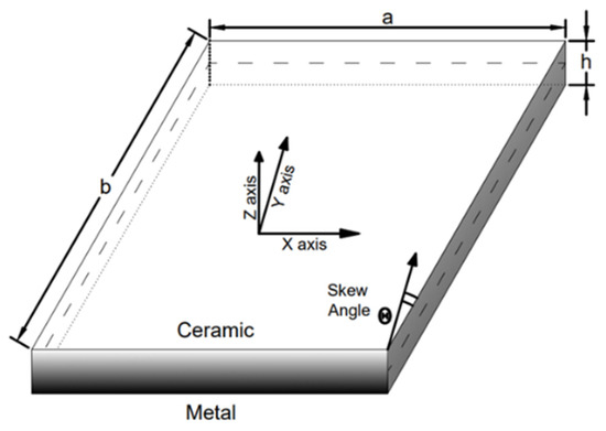
Figure 1.
Geometry of skew functionally graded plate.
2.2. Material Homogenization Scheme
The volume fraction of the ceramic material is determined according to the power law described in Equation (1), with the index (n) and the distance from the midplane (z) of the plate.
The value of n will range between zero and infinity where zero corresponds to the purely ceramic phase and infinity corresponds to the purely metallic phase, respectively. Vm denotes the volume fraction of the metallic phase, whereas Vc is the volume fraction of the ceramic phase, and the two are related as Vm = 1 − Vc. Material properties such as modulus of elasticity, E(z), and Poisson ratio, ν(z), can be estimated as a function of distance from the midplane, z. The homogenization schemes which are used for the determination of the mechanical properties in the FGM plate are Voigt’s rule of mixtures (RM) and the Mori–Tanaka (MT) scheme. The variation in material properties such as Modulus of Elasticity and Poisson ratio across thickness is defined according to Voigt’s rule of mixture scheme given in Equations (2) and (3).
The variation in material properties such as effective bulk modulus (K) and effective shear modulus (G) across the plate’s thickness is defined according to the Mori–Tanaka scheme [43] given in Equations (4) and (5). The coefficients CK and CG are defined in Equation (6). The bulk modulus of isotropic material phases is calculated using Equation (7). Finally, the modulus of elasticity Ez and Poisson ratio υz at a particular depth are described by Equation (8).
2.3. Displacement Field Definition
The displacement fields have six nodal unknowns: u, v, w, ϕsx, ϕsy, and ψ, respectively. The displacements on the plate’s mid-plane along the x, y, and z-axes are denoted by u, v, and w, respectively. The rotation of the plate’s transverse normal about the y-axis and x-axis are ϕsx and ϕsy while ψ is the variation in the plate’s stretching deformation due to the load application. The proposed HYSD uses the shape function f(z) associated with ϕsx and ϕsy which is expressed in Equation (9) for defining the distribution of the transverse shear strain across the plate’s thickness. The shape function g(z) associated with ψ is defined in Equation (10) to account for the thickness stretching deformation of the plate.
The displacement fields for the in-plane u, v, and transverse w displacements are defined in Equations (11)–(13) using the shape function f(z) and g(z).
For C0 continuity of finite element analysis, the out-of-plane derivatives are problematic because the expression of the strain will involve terms with second-order derivatives. C1 continuity must be satisfied for those second-order derivative terms. The C1 continuity requirement is very complex and difficult to model. Hence, the out-of-plane derivatives are substituted with additional nodal unknowns to ensure that the displacement field variables are continuous within elements. These substitutions introduce artificial constraints expressed in Equation (14) in the governing equation of the plate and require application of the penalty approach during finite element formulation.
The resultant modified displacement fields for in-plane displacements are expressed in Equations (15) and (16).
2.4. Strain–Displacement Relationship
The strain–displacement relationships which are obtained from the differentiation of the displacement field equations are described as follows:
2.5. Constitutive Relationship
The linear constitutive relationship between the stresses and the strain is given by the constitutive matrix [44] expressed in Equation (19). The effective material properties such as E(z) and ν(z) are defined according to Voigt’s rule of mixtures or the Mori–Tanaka scheme [43]. Qij described in Equation (18) varies with the fluctuation in E(z) and ν(z) across the plate thickness.
3. Finite Element Formulation
The governing differential equation of the plate can be obtained using the application of the principal of virtual work on the strain energy U, external work W, and artificial constraint C of the FGM plate system as described in Equation (20).
The strain energy of the system can be expressed by Equation (21). The strain vectors can be represented as the product of thickness coordinate matrix [H], differential operator matrix [B] described in Appendix A, and mid-plane displacements {Xo} described in Equation (22). Similarly, the work done by the external load is defined in Equation (23). The external load vector q = [0 0 qo 0 0 0 0 0] in which qo (x, y) corresponds to the transverse load acting on the midplane.
The nine-node isoparametric Lagrangian shape functions were used in the development of the isoparametric finite element for the analysis of the FGM plate. The use of a nine-node element allows (3 × 3) a full integration scheme to be implemented and this results in improvement in the accuracy of the results. The midplane displacement can be interpolated using the isoparametric shape functions described in Equation (24).
The material rigidity matrix [D] is calculated using the constitutive matrix given in Equation (19) and thickness coordinate matrix [H]. This matrix helps in the implementation of the proposed HSDT as an equivalent single layer theory to convert the 3D domain to the 2D domain for the analysis.
Finally, the application of Equations (21)–(25) in Equation (20) results in the governing equation for the static analysis of the FGM plate described in Equation (26). The stiffness matrix [K], constraint stiffness matrix [Kc], and force matrix [F] can be derived from Equation (26) to establish the relationship between load and displacement expressed in Equation (28). Since the penalty approach was used for the finite element formulation, the effect of the artificial constraints on the displacements is negligible and the relationship K Xo = F holds true for the present static analysis.
4. Results
4.1. Model Convergence and Validation
In this section, the static analysis is performed for the calculation of displacement and stresses of the FGM plate for different types of loading, plate geometries, and boundary conditions. The mechanical properties of the material used in FGM plate are listed in Table 1.

Table 1.
Mechanical properties of the material used in functionally graded material.
The different boundary conditions of the plate are described in Table 2. Here, all side simply supported (SSSS), all sides clamped (CCCC), two sides simply supported two side clamped (SCSC), and two sides simply supported two sides free (SFSF) are defined by restraining the various displacements and rotations as the edges.
Table 2.
Definition of the various boundary condition for the analysis of the plate.
The FE model used for the static analysis is developed from the governing equations derived from principle of virtual work based on the proposed novel HSDT. The nine-noded Lagrangian isoparametric shape functions are utilized to write the in-house code for the FE formulation using MATLAB programming language. The FE analysis is performed for a homogeneous isotropic square simply supported plate with a/h = 10 for mesh convergence and assessment of FE model performance. The modulus of elasticity, E = 210 GPa, and Poisson ratio, ν = 0.3. The plate is subjected to a uniformly distributed load. The different mesh sizes are used for the convergence studies and findings in terms of non-dimensional central deflections and stresses defined by Equations (29)–(31) are expressed in Table 3. The model is compared with the results of Shimpi et al. [14] and Hebali et al. [33] for validation and accuracy. It was observed that sufficient convergence can be achieved for a mesh size with 11X11 elements for displacement while convergence in the stresses requires finer mesh sizes because stresses are derived quantities.
Table 3.
Non-dimensional central deflection and stresses in a homogeneous isotropic square plate subjected to the uniformly distributed load.
The volume fraction of the ceramic phase decreases with index (n) and it has a significant effect on the performance of the FGM plate. The sinusoidal loading is applied on a thin (a/h = 10) simply supported square FGM plate. The mechanical properties of the Al/Al2O3 FGM is estimated using RM and MT schemes. The volume fraction index is varied from ceramic to metallic phase to examine its effect on the displacement and stresses of the plate. The results are compared with the results of Zenkour [27] where the thickness stretching effect is ignored and Hebali et al. [33], where the effect of thickness stretching is considered. The RM method captures axial stress results accurately while giving the lower plate’s central deflection values. The MT scheme captured transverse shear stresses effectively but yielded higher values of deflection. Table 4 presents the results for comparison for non-dimensional displacement, axial stress, and transverse shear stress defined in Equation (30). The gradual increase in displacement with volume fraction index can be observed. The decrease in ceramic volume fraction with increase in volume fraction index decreases the flexural rigidity of the plate.
Table 4.
Non-dimensional central deflection and axial stress of an FGM plate subjected to uniformly distributed load under SSSS.
The effect of material homogenization methods such as the Mori–Tanaka scheme and Voigt’s rule of mixture is investigated using results derived by Ferreira et al. [29] and Qian et al. [28]. A square plate made of Al/ZrO2-1 FGM is analyzed for uniformly distributed load and simply supported boundary condition. The side-to-thickness ratio (a/h) and volume fraction index (n) are varied. The FE analysis is performed, and results are shown in Table 5 for comparison with the non-dimensional central deflection of the FGM plate expressed in Equation (31). The results of non-dimensional central deflection show excellent agreement with reference results for both the RM and MT schemes with RM producing slightly lower values and the MT scheme yielding higher values.
Table 5.
Non-dimensional central deflection (w3) of the simply supported square FGM plate effective elastic properties computed by Voigt’s rule of mixtures and Mori–Tanaka scheme.
The effect of variation in the side-to-thickness ratio is examined to elaborate the thickness stretching effect which was incorporated in development of the FE model of the square Al-ZrO2-1 FGM plate. The effective mechanical properties across the thickness are defined by the Mori–Tanaka scheme. The uniformly distributed load is applied on a simply supported square FGM plate with varying side-to-thickness ratios and power law indices. The results are presented in Table 6 for comparison with the results given by Ferreira et al. [29] and Qian et al. [28] for the non-dimensional central deflection of the FGM plate given in Equation (31).
Table 6.
Effect of the variation in a/h ratio on the non-dimensional central displacement (w).
Similarly, another case of the square simply supported Al/Al2O3 FGM plate is taken. The Voigt’s RM method is used to define effective mechanical properties of the plate. The FGM plate is subjected to sinusoidal loading for thick, moderately thick, and thin plates. Table 7 shows the non-dimensional central deflection and axial stress, which can be compared with the findings of Carrera et al. [32], Neves et al. [45], and Hebali et al. [33] for sinusoidal load and non-dimensional central deflection and axial stress defined in Equation (32). The results predicted by the present theory strongly match the results of the existing literature for thin plates.
Table 7.
The variation in non-dimensional central displacement and axial stress subjected to sinusoidal loading.
The deflection is restrained by the clamped boundary conditions while the free edges tend to increase the deflection. The effect of various boundary conditions on the displacement and stresses defined in Equation (33) is studied. The mechanical properties of Al/ZrO2-2 FGM is defined by the MT scheme. A thick (a/h = 5) square FGM plate subjected to a uniformly distributed load is used for analysis. The analysis results are compared with multiquadric and thin plate splines results of Gilhooley et al. [30]. The results presented in Table 8 demonstrate the expected lower values of displacement for clamped boundary conditions and higher values for FGM plates with free edges.
Table 8.
Effect of the different boundary conditions on the non-dimensional central deflection and axial stress of an FGM plate subjected to uniformly distributed load.
The stiffening effect of the skew simply supported FGM plate is explored for various skew angles. The mechanical properties of the Ti6Al4V/Si3N4 FGM plate are described by the MT scheme. The static analysis is performed for thick, moderately thick, and thin skew FGM plates all having edges of equal length. Uniformly distributed load is applied and the plate’s non-dimensional central deflection defined by Equation (34) is estimated for various skew angles and side-to-thickness ratios. The deflection of the plate is compared with Liew and Han [46] for isotropic ceramic phase. It is observed in Table 9 that the increase in the skew angle has an overall stiffening effect on the values of the displacement and larger skew angles give better performance. The effect of decreasing the stiffer ceramic volume fraction with the increase in volume fraction index yields higher displacement values.
Table 9.
Effect of the skewness angles on the non-dimensional central deflection (w6) of the simply supported FGM plate.
The clamped edges of the skew FGM plate remove all the complexities arising from ambiguities about rotational displacement at the inclined edges. The effective mechanical properties of the Ti6Al4V/Si3N4 FGM plate are described by the RM method. All sides of the FGM plate are of equal length 2a and 2a/h = 100. The non-dimensional central deflection of the FGM plate is estimated for various skew angles. The results of entirely ceramic isotropic plate are compared with Butalia et al. [47] in Table 10 for non-dimensional central displacement defined by Equation (34). The clamped edges produce smaller displacement because angular displacements are restrained at the edges.
Table 10.
Effect of the skewness angles on the non-dimensional central deflection (w6) of the FGM plate with clamped edges.
4.2. Parametric Studies
The effect of changing the boundary conditions, volume fraction index, side-to-thickness ratio, and aspect ratio on the FGM plate is studied. The finite element model for the FGM plate under the application of a uniformly distributed load is studied. The metallic phase of the FGM plate is made up of aluminum while the ceramic phase is made with Alumina. The plate’s non-dimensional central deflection, axial stress, and transverse shear stresses are defined in Equation (35).
The effect of volume fraction index n on the non-dimensional central deflection of the FGM plate for various boundary conditions is shown in Figure 2. It can be seen that the deflection increases with the decrease in stiffer ceramic material phase volume. The deflection is maximum for the simply supported free boundary condition and it is minimum for the all sides clamped condition.
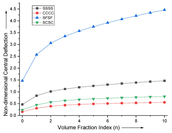
Figure 2.
Effect of vole fraction index (n) on non−dimensional central deflection of the plate.
The effect of the aspect ratio of the FGM plate is investigated by varying aspect ratio and volume fraction index fixing a/h = 10. The dependence of plate’s non-dimensional central deflection on the a/b ratio is depicted in Figure 3. It is observed that the effect of change in aspect ratio a/b becomes negligible after a/b = 3. It is more prominent when a/b < 1.
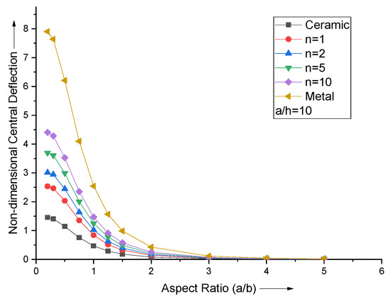
Figure 3.
Effect of aspect ratio (a/b) on non−dimensional central deflection of the plate.
For various values of the volume fraction index, the effect of changing the side-to-thickness ratio (a/h) on the non-dimensional central deflection for a square simply supported FGM plate is shown in Figure 4. After a/h = 10, it is observed that the non-dimensional centroidal displacement curves follow a parallel line pattern.
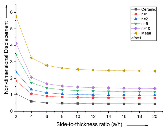
Figure 4.
Effect of side−to−thickness ratio (a/h) on non−dimensional central deflection of the plate.
When the volume fraction index is varied, the non-dimensional normal stress curves attain the extremum near the top and bottom surfaces of the FGM plate, as shown in Figure 5. The neutral axis plane shifts towards the top metallic portion for lower values of n and then comes back to midplane for higher n values.
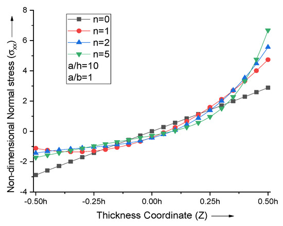
Figure 5.
Effect of volume fraction index (n) on non−dimensional normal stresses of the plate.
When the aspect ratio is varied, the extremum of non-dimensional normal stress at the top and bottom surfaces of the FGM plate decreases with the increase in aspect ratio. The non-dimensional normal stress curves attain zero at Z = 0.075 for all aspect ratios of the FGM plate with n = 2, as shown in Figure 6.
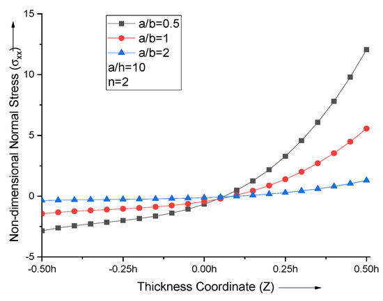
Figure 6.
Effect of aspect ratio (a/b) on non−dimensional normal stresses of the plate.
The increase in the side-to-thickness ratio (a/h) leads to an increase in the maximum normal stress value. For all the values of the side-to-thickness ratio with n = 2, non-dimensional normal stress curves attain zero at Z = 0.075, as shown in Figure 7.
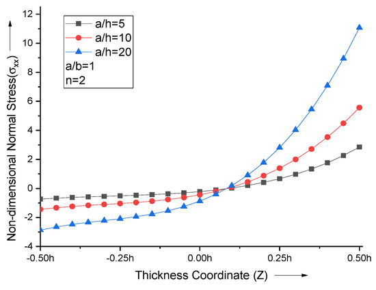
Figure 7.
Effect of side−to−thickness ratio (a/h) on non−dimensional normal stresses of the plate.
The non-dimensional transverse shear stress curves follow the parabolic profile, which attains a maximum value near the middle portion of the FGM plate, as shown in Figure 8. The point of maxima shifts towards the top metallic portion for lower values of n and then comes back to the midplane for higher n values.
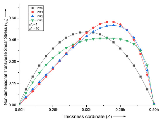
Figure 8.
Effect of volume fraction index (n) on non−dimensional transverse shear stresses of the plate.
An increase in the aspect ratio (a/b) decreases the maximum transverse shear stress. For all the aspect ratios with n = 2, non-dimensional transverse shear stress curves acquire maxima at Z = 0.2, as shown in Figure 9.
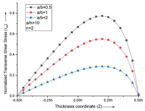
Figure 9.
Effect of aspect ratio (a/b) on non−dimensional transverse shear stresses of the plate.
With the increase in the side-to-thickness ratio (a/h), the maximum transverse shear stress value increases. The transverse shear stress curves for all the values of the side-to-thickness ratio with n = 2 attain maxima Z = 0.2, as shown in Figure 10.
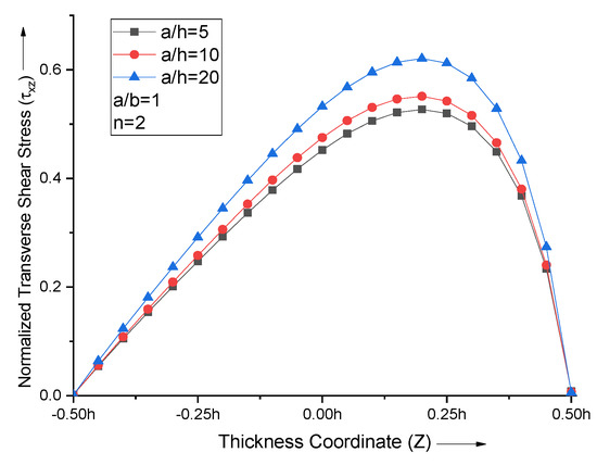
Figure 10.
Effect of side−to−thickness ratio (a/h) on non−dimensional normal stresses of the plate.
The variation in the displacement across the simply supported square FGM plate for n = 1 can be shown in Figure 11. It can be seen that the plate’s deflection obeys the boundary condition and the maximum displacement can be observed at the center of the plate. The transverse shear stress appears to give a maximum response at the mid-point of the edge which allows the corresponding shear rotation at the edge.
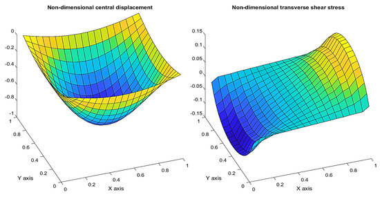
Figure 11.
Variation in the non−dimensional displacement (w) and transverse shear stress (τxz) across the FGM plate.
5. Conclusions
The nine-node isoparametric element-based FE model was formulated on refined hybrid polynomial and hyperbolic shape function-based higher-order shear deformation theory to analyze the FGM plate for various loading conditions. The thickness stretching effect was incorporated. The principle of virtual work was applied for the evolution of elementary stiffness and force matrix. The finite element analysis results were compared with existing literature, and the performance of the finite element model was found to be satisfactory. The model was utilized for parametric studies. The variation in boundary conditions, aspect ratio, side-to-thickness ratio, skewness, and volume fraction index was completed. The following observations were made regarding non-dimensional central deflection and stresses.
- Non-dimensional central deflection of the plate decreases with increase in volume fraction index (n) due to decrease in stiffer ceramic fraction.
- When both the Mori–Tanaka scheme and Voigt’s rule of mixture method are employed to define the effective material properties of the FGM plate, the Mori–Tanaka scheme gives more deflection.
- The plate’s non-dimensional central deflection is maximum for the SFSF boundary condition and minimum for the CCCC boundary condition.
- Variation in the plate’s non-dimensional central deflection with aspect ratio is negligible when a/b > 3.
- With the variation in side-to-thickness ratio, the plate’s non-dimensional central deflection shows a parallel line pattern when a/h > 10.
- The non-dimensional normal stress curves attain extremum near the top and bottom surfaces of the FGM plate. When the volume fraction index increases, the maximum value of axial stress also increases.
- When the volume fraction index is greater than zero, the peak of the parabolic profile of non-dimensional transverse shear stress shows a shift towards the top surface of the plate.
- Non-dimensional normal stress decreases with an increase in the aspect ratio, and its value increases with the increase in the side-to-thickness ratio. It has the same location for the zero stress value, irrespective of a/h or a/b ratio for a particular volume fraction index.
- The non-dimensional transverse shear stress decreases with an increase in the aspect ratio, and it increases with the increment in the side-to-thickness ratio. It attains the maxima at the same location irrespective of a/h or a/b ratio for a particular volume fraction index.
- The non-dimensional central deflection of the skewed FGM plate decreases with increase in skew angles because of the stiffening effect of larger skew angles.
Author Contributions
Conceptualization, J.S. and A.K.; methodology, J.S.; software, A.K.; validation, J.S. and A.K.; formal analysis, J.S. and A.K.; investigation, J.S.; resources, J.S.; data curation, J.S. and A.K.; writing—original draft preparation, M.S. and D.B.-H.; writing—review and editing, M.S., D.B.-H. and B.S.-B.; visualization, J.S. and M.S.; supervision, D.B.-H., B.S.-B. and A.K.; project administration, A.K. and B.S.-B.; funding acquisition, M.S., D.B.-H. and B.S.-B. All authors have read and agreed to the published version of the manuscript.
Funding
This research received no external funding besides statutory research of particular scientific units.
Institutional Review Board Statement
Not applicable.
Informed Consent Statement
Not applicable.
Data Availability Statement
Not applicable.
Acknowledgments
This work was financially supported by the Ministry of Education and Science—Poland, within the grant number WZ/WB-IIL/4/2020 and FD-IL-003, FD-20/IL-4/068.
Conflicts of Interest
The authors declare no conflict of interest.
Appendix A
References
- Udupa, G.; Rao, S.S.; Gangadharan, K.V. Functionally Graded Composite Materials: An Overview. Procedia Mater. Sci. 2014, 5, 1291–1299. [Google Scholar] [CrossRef]
- Vel, S.S.; Batra, R.C. Three-Dimensional Exact Solution for the Vibration of Functionally Graded Rectangular Plates. J. Sound Vib. 2004, 272, 703–730. [Google Scholar] [CrossRef]
- Kashtalyan, M. Three-Dimensional Elasticity Solution for Bending of Functionally Graded Rectangular Plates. Eur. J. Mech.-A/Solids 2004, 23, 853–864. [Google Scholar] [CrossRef]
- Jin, G.; Su, Z.; Shi, S.; Ye, T.; Gao, S. Three-Dimensional Exact Solution for the Free Vibration of Arbitrarily Thick Functionally Graded Rectangular Plates with General Boundary Conditions. Compos. Struct. 2014, 108, 565–577. [Google Scholar] [CrossRef]
- Woodward, B.; Kashtalyan, M. Three-Dimensional Elasticity Solution for Bending of Transversely Isotropic Functionally Graded Plates. Eur. J. Mech.-A/Solids 2011, 30, 705–718. [Google Scholar] [CrossRef] [Green Version]
- Reddy, J.N. A Simple Higher-Order Theory for Laminated Composite Plates. J. Appl. Mech. Trans. ASME 1984, 51, 745–752. [Google Scholar] [CrossRef]
- Zhang, P.; Qi, C.; Fang, H.; He, W. Three Dimensional Mechanical Behaviors of In-Plane Functionally Graded Plates. Compos. Struct. 2020, 241, 112124. [Google Scholar] [CrossRef]
- Wu, C.P.; Chen, W.Y. Vibration and Stability of Laminated Plates Based on a Local High Order Plate Theory. J. Sound Vib. 1994, 177, 503–520. [Google Scholar] [CrossRef]
- Cho, K.N.; Bert, C.W.; Striz, A.G. Free Vibrations of Laminated Rectangular Plates Analyzed by Higher Order Individual-Layer Theory. J. Sound Vib. 1991, 145, 429–442. [Google Scholar] [CrossRef]
- Icardi, U. Eight-Noded Zig-Zag Element for Deflection and Stress Analysis of Plates with General Lay-Up. Compos. Part B Eng. 1998, 29, 425–441. [Google Scholar] [CrossRef]
- Kumar, A.; Chakrabarti, A.; Bhargava, P. Vibration of Laminated Composites and Sandwich Shells Based on Higher Order Zigzag Theory. Eng. Struct. 2013, 56, 880–888. [Google Scholar] [CrossRef]
- Bauchau, O.A.; Craig, J.I. Kirchhoff Plate Theory. In Structural Analysis; Bauchau, O.A., Craig, J.I., Eds.; Springer: Dordrecht, The Netherlands, 2009; pp. 819–914. [Google Scholar] [CrossRef]
- Yu, W. Mathematical Construction of a Reissner-Mindlin Plate Theory for Composite Laminates. Int. J. Solids Struct. 2005, 42, 6680–6699. [Google Scholar] [CrossRef] [Green Version]
- Shimpi, R.P.; Arya, H.; Naik, N.K. A Higher Order Displacement Model for the Plate Analysis. J. Reinf. Plast. Compos. 2003, 22, 1667–1688. [Google Scholar] [CrossRef]
- Talha, M.; Singh, B.N. Static Response and Free Vibration Analysis of FGM Plates Using Higher Order Shear Deformation Theory. Appl. Math. Model. 2010, 34, 3991–4011. [Google Scholar] [CrossRef]
- Touratier, M. An Efficient Standard Plate Theory. Int. J. Eng. Sci. 1991, 29, 901–916. [Google Scholar] [CrossRef]
- Thai, C.H.; Ferreira, A.J.M.; Bordas, S.P.A.; Rabczuk, T.; Nguyen-Xuan, H. Isogeometric Analysis of Laminated Composite and Sandwich Plates Using a New Inverse Trigonometric Shear Deformation Theory. Eur. J. Mech.-A/Solids 2014, 43, 89–108. [Google Scholar] [CrossRef]
- Soldatos, K.P. A Transverse Shear Deformation Theory for Homogeneous Monoclinic Plates. Acta Mech. 1992, 94, 195–220. [Google Scholar] [CrossRef]
- Grover, N.; Maiti, D.K.; Singh, B.N. A New Inverse Hyperbolic Shear Deformation Theory for Static and Buckling Analysis of Laminated Composite and Sandwich Plates. Compos. Struct. 2013, 95, 667–675. [Google Scholar] [CrossRef]
- Karama, M.; Afaq, K.S.; Mistou, S. A New Theory for Laminated Composite Plates. Proc. Inst. Mech. Eng. Part L J. Mater. Des. Appl. 2009, 223, 53–62. [Google Scholar] [CrossRef]
- Li, M.; Guedes Soares, C.; Yan, R. A Novel Shear Deformation Theory for Static Analysis of Functionally Graded Plates. Compos. Struct. 2020, 250, 112559. [Google Scholar] [CrossRef]
- Mahi, A.; Adda Bedia, E.A.; Tounsi, A. A New Hyperbolic Shear Deformation Theory for Bending and Free Vibration Analysis of Isotropic, Functionally Graded, Sandwich and Laminated Composite Plates. Appl. Math. Model. 2015, 39, 2489–2508. [Google Scholar] [CrossRef]
- Natarajan, S.; Manickam, G. Bending and Vibration of Functionally Graded Material Sandwich Plates Using an Accurate Theory. Finite Elem. Anal. Des. 2012, 57, 32–42. [Google Scholar] [CrossRef] [Green Version]
- Nelson, R.B.; Lorch, D.R. A Refined Theory for Laminated Orthotropic Plates. J. Appl. Mech. Trans. ASME 1974, 41, 177–183. [Google Scholar] [CrossRef]
- Neves, A.M.A.; Ferreira, A.J.M.; Carrera, E.; Cinefra, M.; Roque, C.M.C.; Jorge, R.M.N.; Soares, C.M.M. A Quasi-3D Hyperbolic Shear Deformation Theory for the Static and Free Vibration Analysis of Functionally Graded Plates. Compos. Struct. 2012, 94, 1814–1825. [Google Scholar] [CrossRef]
- Mantari, J.L.; Guedes Soares, C. Generalized Hybrid Quasi-3D Shear Deformation Theory for the Static Analysis of Advanced Composite Plates. Compos. Struct. 2012, 94, 2561–2575. [Google Scholar] [CrossRef]
- Zenkour, A.M. Generalized Shear Deformation Theory for Bending Analysis of Functionally Graded Plates. Appl. Math. Model. 2006, 30, 67–84. [Google Scholar] [CrossRef] [Green Version]
- Qian, L.F.; Batra, R.C.; Chen, L.M. Static and Dynamic Deformations of Thick Functionally Graded Elastic Plates by Using Higher-Order Shear and Normal Deformable Plate Theory and Meshless Local Petrov–Galerkin Method. Compos. Part B Eng. 2004, 35, 685–697. [Google Scholar] [CrossRef]
- Ferreira, A.J.M. Static Analysis of Functionally Graded Plates Using Third-Order Shear Deformation Theory and a Meshless Method. Compos. Struct. 2005, 69, 449–457. [Google Scholar] [CrossRef]
- Gilhooley, D.F.; Batra, R.C.; Xiao, J.R.; McCarthy, M.A.; Gillespie, J.W. Analysis of Thick Functionally Graded Plates by Using Higher-Order Shear and Normal Deformable Plate Theory and MLPG Method with Radial Basis Functions. Compos. Struct. 2007, 80, 539–552. [Google Scholar] [CrossRef]
- Mechab, I.; Atmane, H.A.; Tounsi, A.; Belhadj, H.A.; Bedia, E.A.A. A Two Variable Refined Plate Theory for the Bending Analysis of Functionally Graded Plates. Acta Mech. Sin. 2010, 26, 941–949. [Google Scholar] [CrossRef]
- Carrera, E.; Brischetto, S.; Cinefra, M.; Soave, M. Effects of Thickness Stretching in Functionally Graded Plates and Shells. Compos. Part B Eng. 2011, 42, 123–133. [Google Scholar] [CrossRef] [Green Version]
- Hebali, H.; Tounsi, A.; Houari, M.S.A.; Bessaim, A.; Bedia, E.A.A. New Quasi-3D Hyperbolic Shear Deformation Theory for the Static and Free Vibration Analysis of Functionally Graded Plates. J. Eng. Mech. 2014, 140, 374–383. [Google Scholar] [CrossRef]
- Singha, M.K.; Prakash, T.; Ganapathi, M. Finite Element Analysis of Functionally Graded Plates under Transverse Load. Finite Elem. Anal. Des. 2011, 47, 453–460. [Google Scholar] [CrossRef]
- Valizadeh, N.; Natarajan, S.; Gonzalez-Estrada, O.A.; Rabczuk, T.; Bui, T.Q.; Bordas, S.P.A. NURBS-Based Finite Element Analysis of Functionally Graded Plates: Static Bending, Vibration, Buckling and Flutter. Compos. Struct. 2013, 99, 309–326. [Google Scholar] [CrossRef] [Green Version]
- Orakdöǧen, E.; Küçükarslan, S.; Sofiyev, A.; Omurtag, M.H. Finite Element Analysis of Functionally Graded Plates for Coupling Effect of Extension and Bending. Meccanica 2010, 45, 63–72. [Google Scholar] [CrossRef]
- Alshorbagy, A.E.; Alieldin, S.S.; Shaat, M.; Mahmoud, F.F. Finite Element Analysis of the Deformation of Functionally Graded Plates under Thermomechanical Loads. Math. Probl. Eng. 2013, 2013, 569781. [Google Scholar] [CrossRef]
- Pindera, M.J.; Dunn, P. Evaluation of the Higher-Order Theory for Functionally Graded Materials via the Finite-Element Method. Compos. Part B Eng. 1997, 28, 109–119. [Google Scholar] [CrossRef]
- Nguyen-Xuan, H.; Tran, L.V.; Nguyen-Thoi, T.; Vu-Do, H.C. Analysis of Functionally Graded Plates Using an Edge-Based Smoothed Finite Element Method. Compos. Struct. 2011, 93, 3019–3039. [Google Scholar] [CrossRef]
- Can, N.; Kurgan, N.; Hassan, A.H.A. Buckling Analysis of Functionally Graded Plates Using Finite Element Analysis. Int. J. Eng. Appl. Sci. 2020, 12, 43–56. [Google Scholar] [CrossRef]
- Naghdabadi, R.; Hosseini Kordkheili, S.A. A Finite Element Formulation for Analysis of Functionally Graded Plates and Shells. Arch. Appl. Mech. 2005, 74, 375–386. [Google Scholar] [CrossRef]
- Taj, M.N.A.G.; Chakrabarti, A.; Hamid, A. Analysis of Functionally Graded Plates Using Higher Order Shear Deformation Theory. Appl. Math. Model. 2013, 37, 8484–8494. [Google Scholar] [CrossRef]
- Mori, T.; Tanaka, K. Average Stress in Matrix and Average Elastic Energy of Materials with Misfitting Inclusions. Acta Metall. 1973, 21, 571–574. [Google Scholar] [CrossRef]
- Timoshenko, S.; Woinowsky-Krieger, S. Theory of Plates and Shells, 2nd ed.; Souza, J., Ed.; McGraw-Hill College: New York, NY, USA, 1959. [Google Scholar]
- Neves, A.M.A.; Ferreira, A.J.M.; Carrera, E.; Roque, C.M.C.; Cinefra, M.; Jorge, R.M.N.; Soares, C.M.M. A Quasi-3D Sinusoidal Shear Deformation Theory for the Static and Free Vibration Analysis of Functionally Graded Plates. Compos. Part B Eng. 2012, 43, 711–725. [Google Scholar] [CrossRef]
- Liew, K.M.; Han, J.-B. Bending Analysis of Simply Supported Shear Deformable Skew Plates. J. Eng. Mech. 1997, 123, 214–221. [Google Scholar] [CrossRef]
- Butalia, T.S.; Kant, T.; Dixit, V.D. Performance of Heterosis Element for Bending of Skew Rhombic Plates. Comput. Struct. 1990, 34, 23–49. [Google Scholar] [CrossRef]
Publisher’s Note: MDPI stays neutral with regard to jurisdictional claims in published maps and institutional affiliations. |
© 2022 by the authors. Licensee MDPI, Basel, Switzerland. This article is an open access article distributed under the terms and conditions of the Creative Commons Attribution (CC BY) license (https://creativecommons.org/licenses/by/4.0/).