
Three-Body Abrasive Wear Behavior of WC-10Cr3C2-12Ni Coating for Ball Mill Liner Application


 ,
, 
Abstract
:1. Introduction
2. Materials and Methods
2.1. Coating Preparation
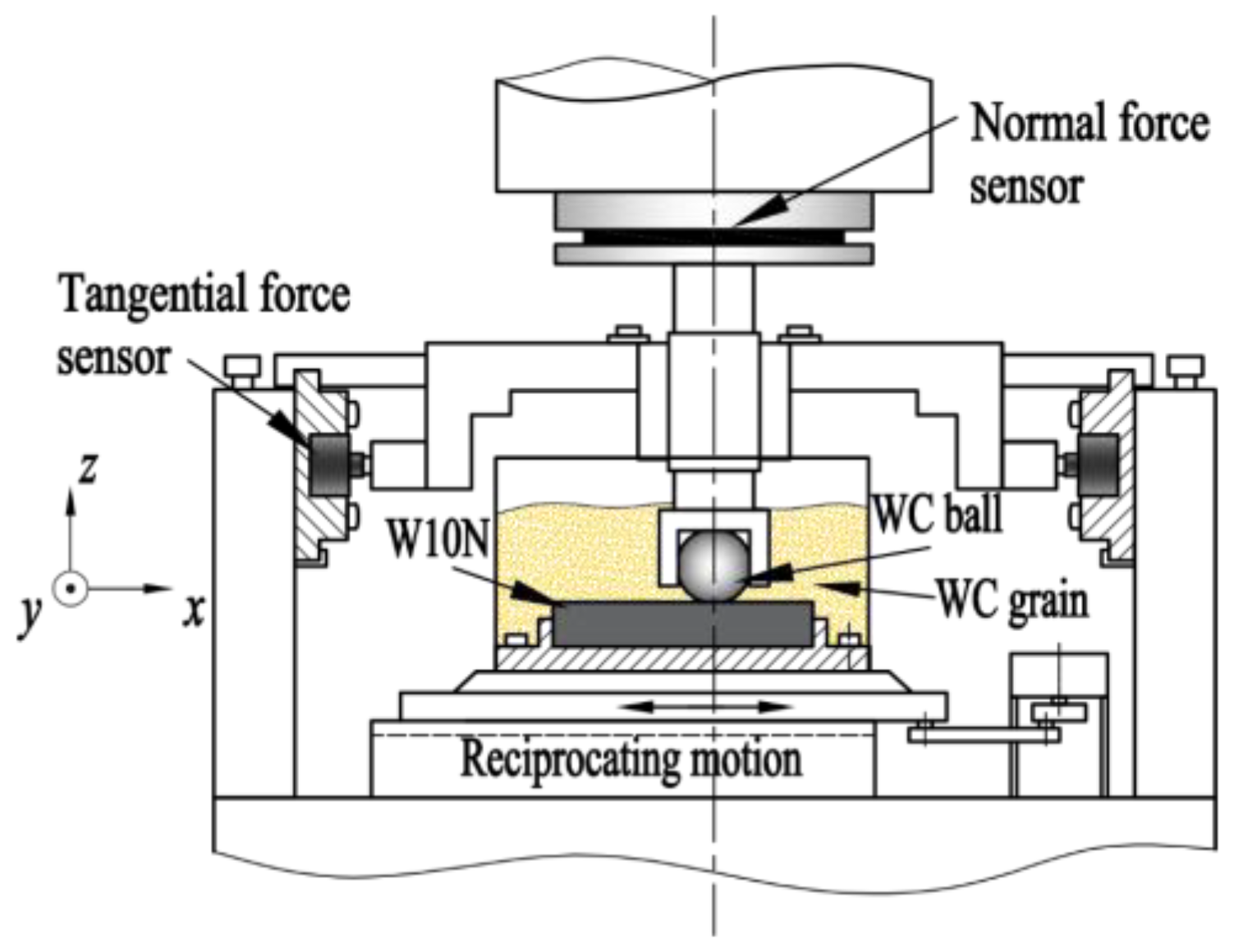
2.2. Test Method
2.3. Analysis and Testing
3. Results
3.1. Coating Microstructure and Hardness
3.2. Friction Coefficient
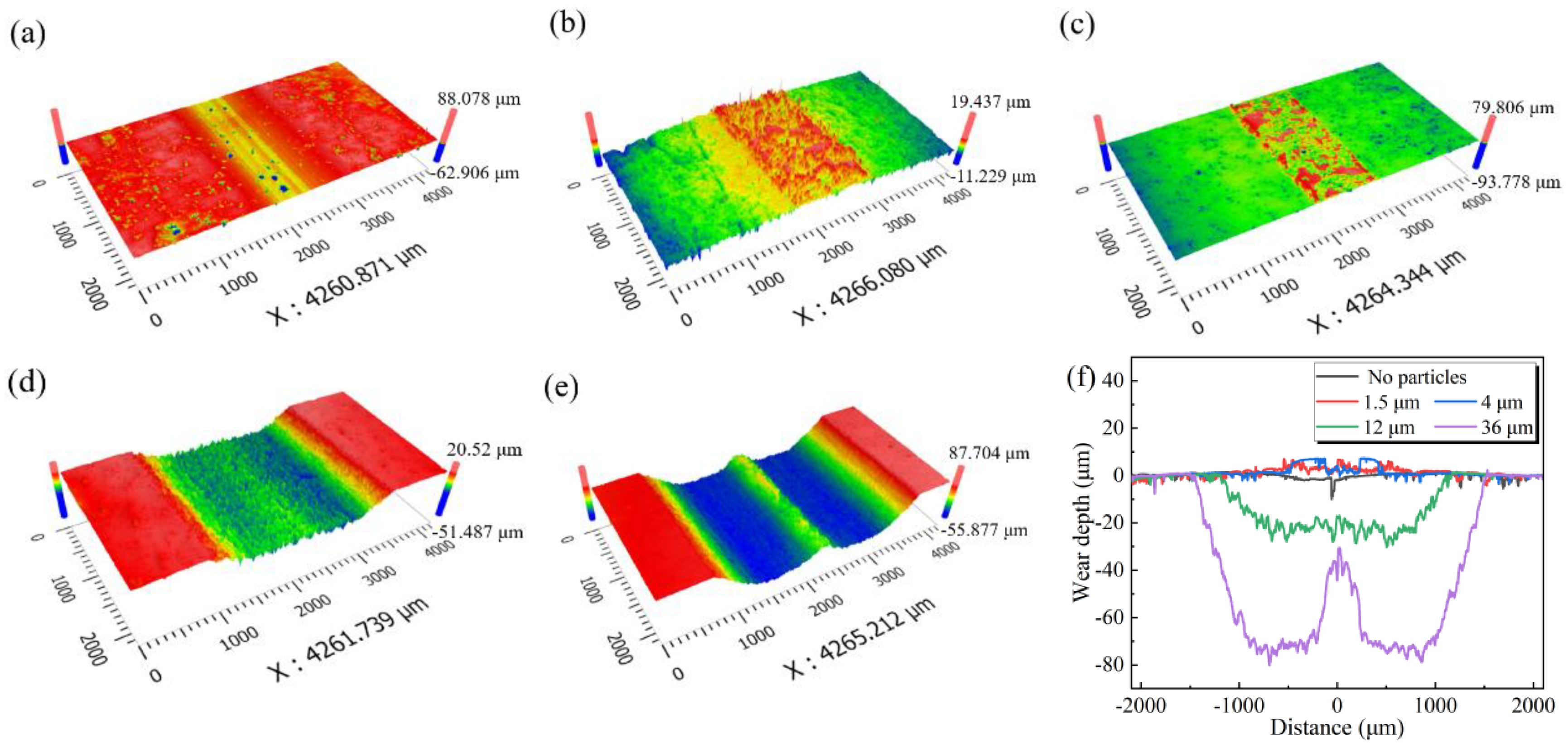
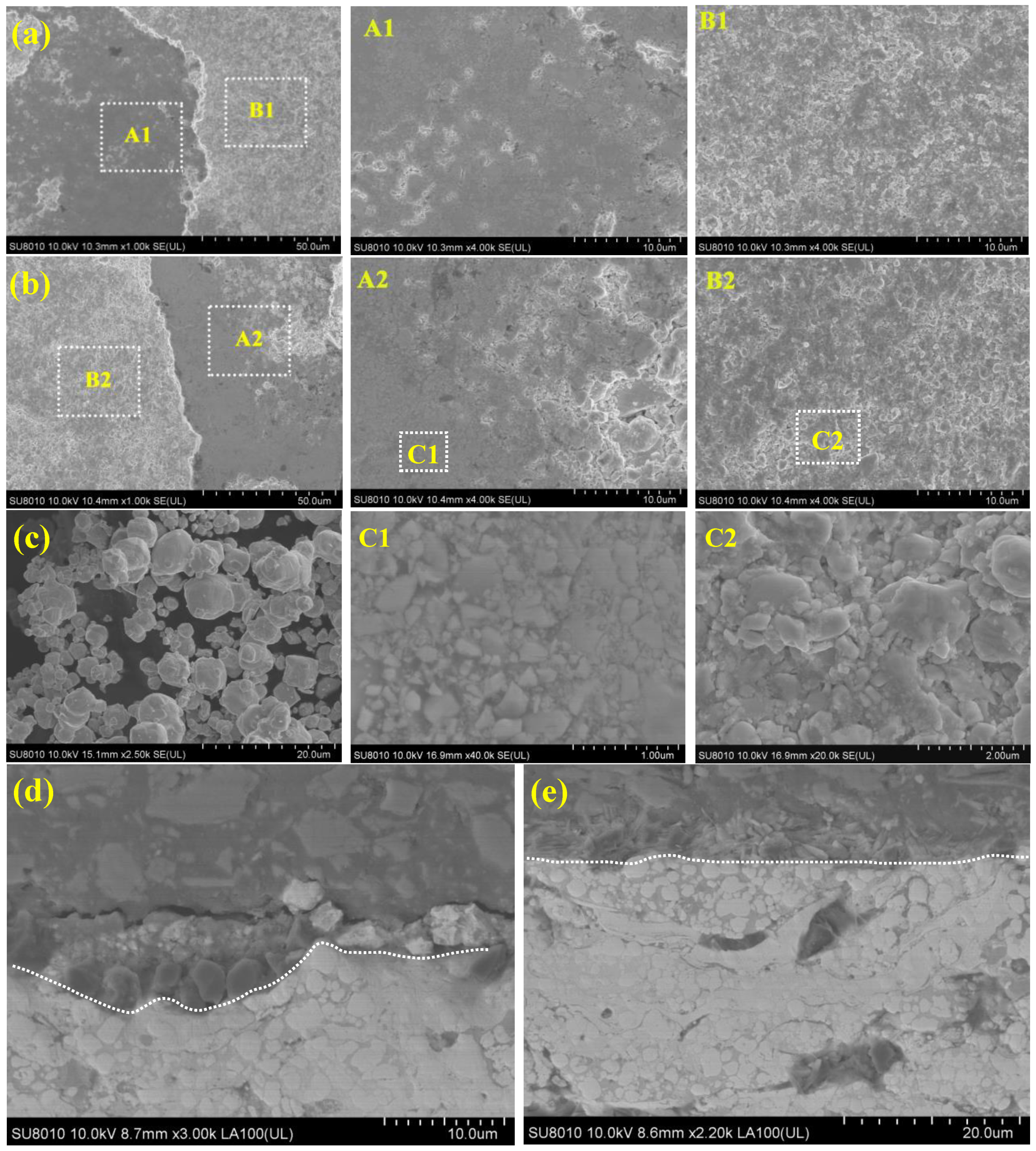
3.3. Surface Morphology of Coatings
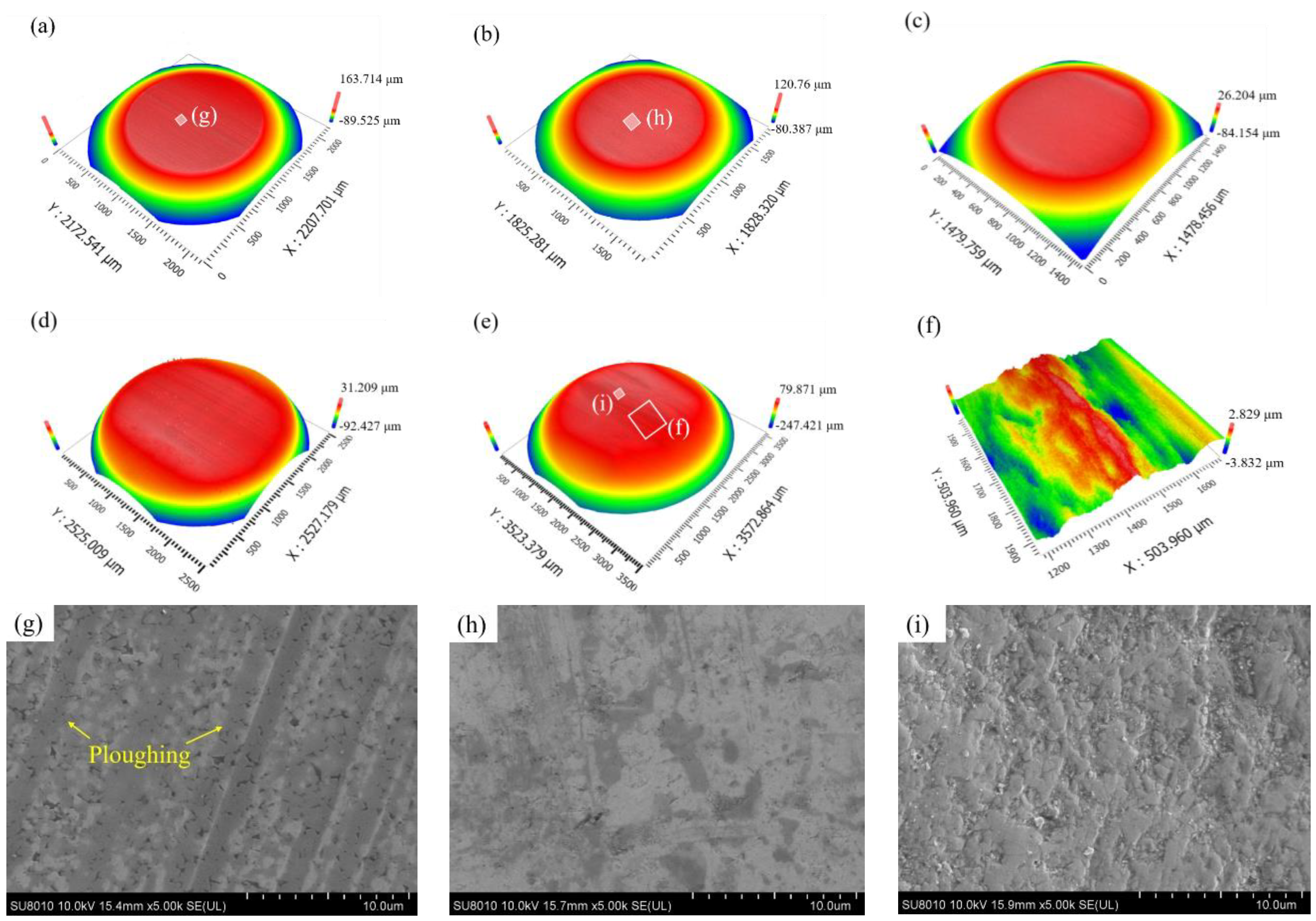
3.4. Surface Morphology of Counter-Balls
3.5. Wear Loss of Tribo-Pairs
4. Discussion
5. Conclusions
- The WC–Cr3C2–Ni coating deposited by the HVOF technology contains phases, such as WC, W2C, Cr7C3, Cr3C2, Cr2O3 and Ni. The coating has a dense and uniform tissue and is closely bonded with the substrate. The average nanohardness of the coating is about 16 GPa, nearly five times higher than that of the 20# steel substrate.
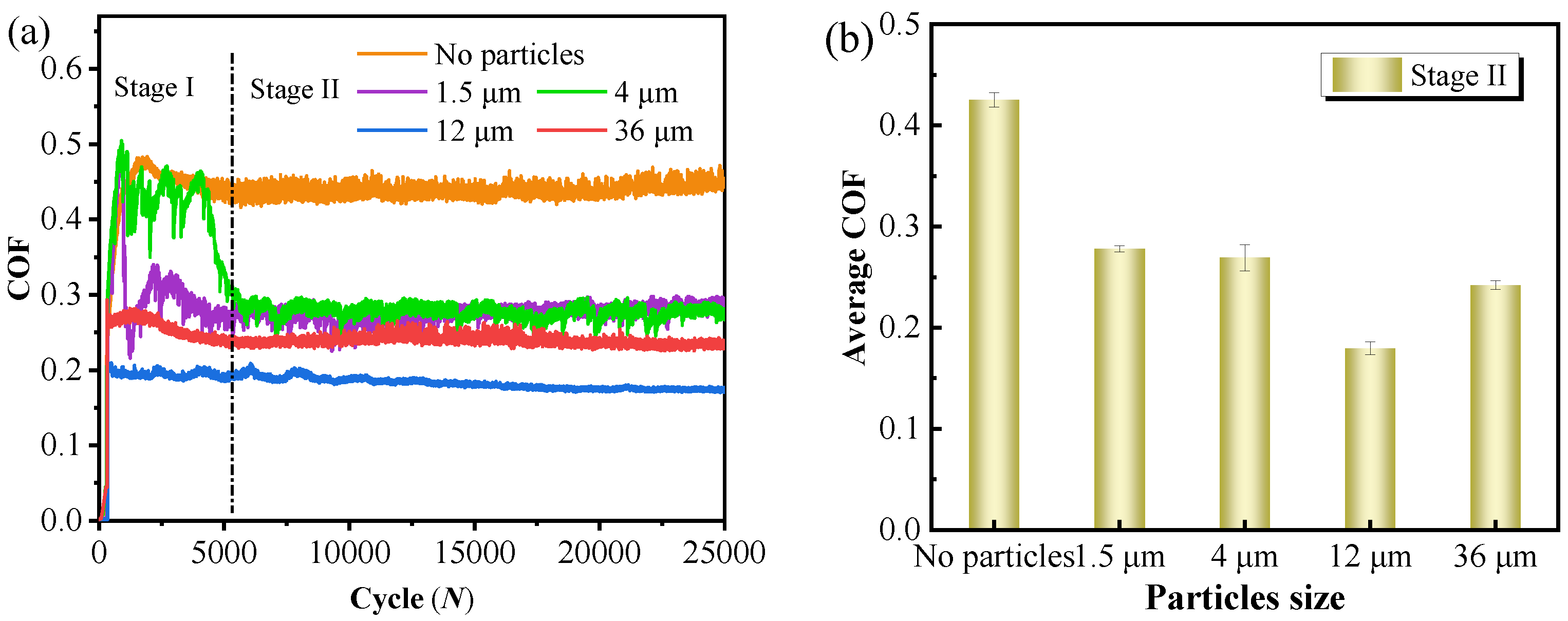
- The COF of tribo-pairs decreases and then increases as the particle size increases. Under 12 μm and 36 μm particle conditions, the COF is reduced by about 60% and 44% in comparison with dry friction, respectively, and the corresponding increase in the coating wear loss is more than 30 times. Furthermore, the wear loss trends for the particle size for friction balls and the coatings are similar.
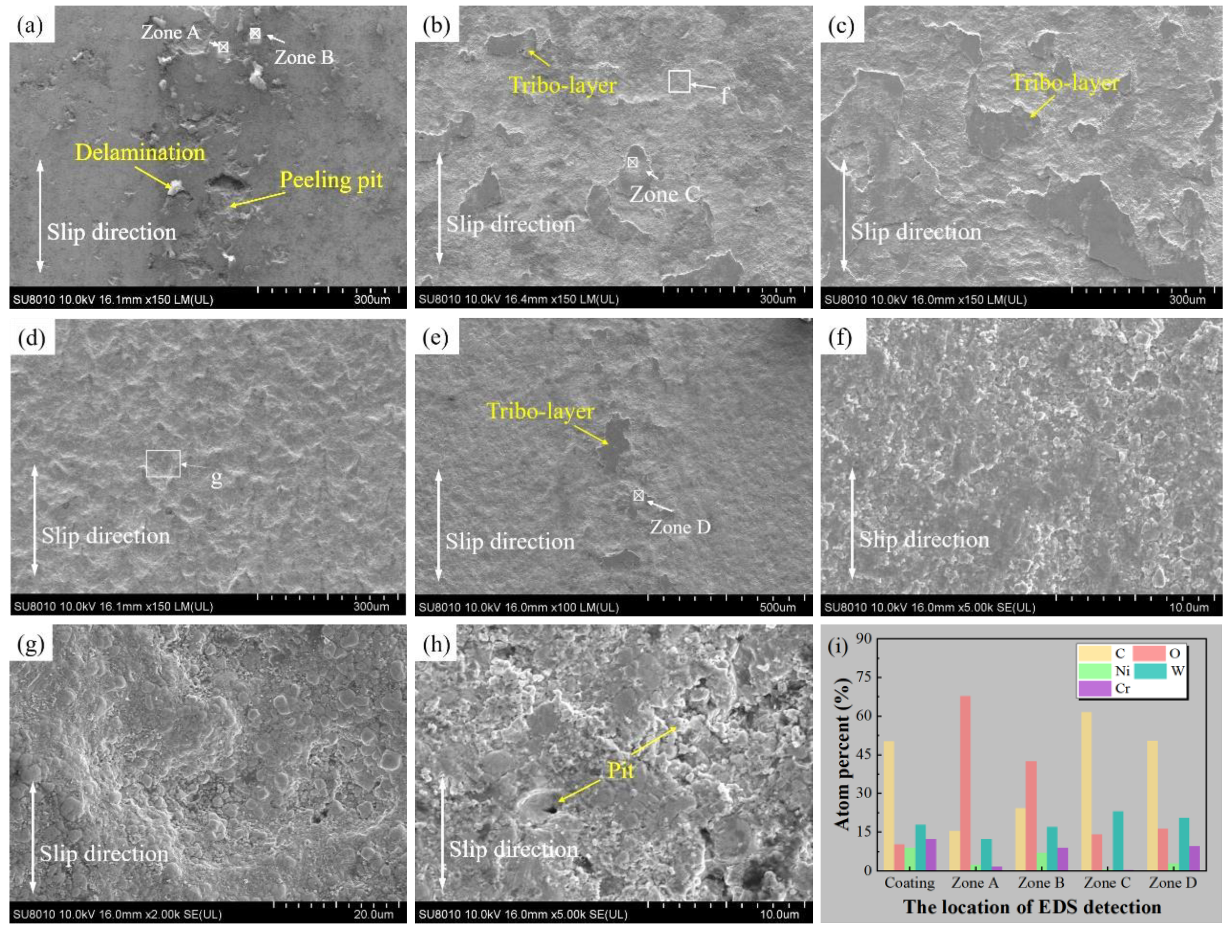
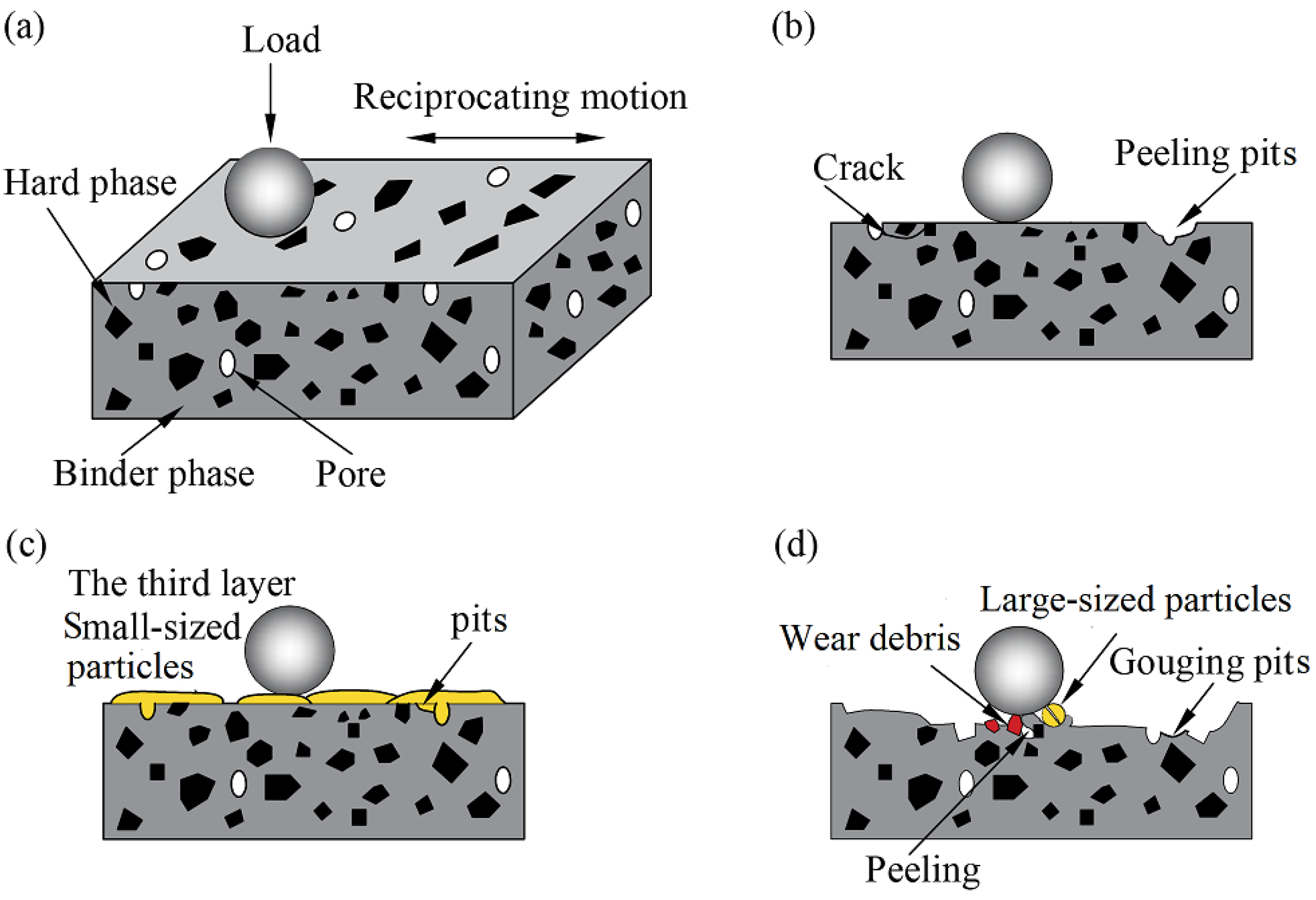
- The particle size has a direct relationship with the coating wear. The surface of the coating appears to wear slightly in the absence of particles, and the wear mechanism is primarily a fatigue wear and minor oxidation wear. Small-sized particles were crushed and adhered to the coating surface, whereafter the extremely fine particles were plasticized to form a large area of tribo-layers by a high stress that reduced the wear and provided protection for the coatings. The protective effect of the abrasive particles fades as the particle size increases, while the chiseling effect intensifies, resulting in a significant tribo-pair loss.
Author Contributions
Funding
Institutional Review Board Statement
Informed Consent Statement
Data Availability Statement
Conflicts of Interest
References
- Liu, C.; Yin, Y.; Li, C.; Xu, M.; Li, R.; Chen, Q. Preparation and properties of lead-free FeS/Cu-Bi composites by flake powder metallurgy via shift-speed ball milling. Adv. Powder Technol. 2022, 33, 103545. [Google Scholar] [CrossRef]
- Im, T.; Pyo, J.; Lee, J.-S.; Lee, C.S. Fabrication of homogeneous nanosized nickel powders using a planetary ball mill: Applications to multilayer ceramic capacitors (MLCCs). Powder Technol. 2021, 382, 118–125. [Google Scholar] [CrossRef]
- Fragoso, A.; Martins, R.F.; César Soares, A. Failure analysis of a ball mill located in a cement’s production line. Eng. Fail. Anal. 2022, 138, 106339. [Google Scholar] [CrossRef]
- Bahadori, A. Chapter 1—Surface Preparation for Coating, Painting, and Lining; Bahadori, A., Ed.; Gulf Professional Publishing: Boston, MA, USA, 2015; pp. 1–105. [Google Scholar]
- Gawlik, J.; Schmidt, J.; Nowak, T.; Wójcicki, Z.; Zagórski, A. Nitrogen as an alloying element improving material properties of the high carbon cast steel for ball mill liner plates. Arch. Civ. Mech. Eng. 2017, 17, 926–934. [Google Scholar] [CrossRef]
- Tyagi, A.; Chourasia, S.; Vats, K.; Murtaza, Q.; Walia, R.S.; Dhawan, V. Tribological behavior of HVOF based composite coatings for wear resistance applications. Mater. Today Proc. 2022, 50, 2376–2380. [Google Scholar] [CrossRef]
- Chourasia, S.; Dhankhar, T.; Shahid, M.; Lal Meena, S.; Sharma, P.; Tyagi, A. Evaluation of as deposit HVOF coating for corrosion and sliding wear resistance. Mater. Today Proc. 2022, 56, 2195–2198. [Google Scholar] [CrossRef]
- Pereira, P.; Vilhena, L.M.; Sacramento, J.; Senos, A.M.R.; Malheiros, L.F.; Ramalho, A. Abrasive wear resistance of WC-based composites, produced with Co or Ni-rich binders. Wear 2021, 482–483, 203924. [Google Scholar] [CrossRef]
- Berger, L.-M. Application of hardmetals as thermal spray coatings. Int. J. Refract. Met. Hard Mater. 2015, 49, 350–364. [Google Scholar] [CrossRef]
- Li, G.; Peng, Y.; Yan, L.; Xu, T.; Long, J.; Luo, F. Effects of Cr concentration on the microstructure and properties of WC-Ni cemented carbides. J. Mater. Res. Technol. 2020, 9, 902–907. [Google Scholar] [CrossRef]
- Yu, H.; Li, W.N.; Jiang, X.Q.; Jiao, P.H. Effect on the microstructure and properties of WC-10% Co alloy Co-doped with NbC and Cr3C2. Adv. Mater. Res. 2013, 621, 58–61. [Google Scholar] [CrossRef]
- Yao, H.-L.; Yang, C.; Yi, D.-L.; Zhang, M.-X.; Wang, H.-T.; Chen, Q.-Y.; Bai, X.-B.; Ji, G.-C. Microstructure and mechanical property of high velocity oxy-fuel sprayed WC-Cr3C2-Ni coatings. Surf. Coat. Technol. 2020, 397, 126010. [Google Scholar] [CrossRef]
- Delanoë, A.; Bacia, M.; Pauty, E.; Lay, S.; Allibert, C.H. Cr-rich layer at the WC/Co interface in Cr-doped WC-Co cermets: Segregation or metastable carbide? J. Cryst. Growth 2004, 270, 219–227. [Google Scholar] [CrossRef]
- Zhou, W.; Zhou, K.; Li, Y.; Deng, C.; Zeng, K. High temperature wear performance of HVOF-sprayed Cr3C2-WC-NiCoCrMo and Cr3C2-NiCr hardmetal coatings. Appl. Surf. Sci. 2017, 416, 33–44. [Google Scholar] [CrossRef]
- Bolelli, G.; Berger, L.-M.; Bonetti, M.; Lusvarghi, L. Comparative study of the dry sliding wear behaviour of HVOF-sprayed WC-(W,Cr)2C-Ni and WC-CoCr hardmetal coatings. Wear 2014, 309, 96–111. [Google Scholar] [CrossRef]
- Matthews, S.; James, B. Review of thermal spray coating applications in the steel industry: Part 1-hardware in steel making to the continuous annealing process. J. Therm. Spray Technol. 2010, 19, 1267–1276. [Google Scholar] [CrossRef]
- Kim, S.S.; Kato, K.; Hokkirigawa, K.; Abe’, H. Wear mechanism of ceramic materials in dry rolling friction. J. Tribol. 1986, 108, 522–526. [Google Scholar] [CrossRef]
- Hu, K.; Liu, X.; Zhang, S.; Xue, Z.; Yang, Y.; Yang, K. Tribocorrosion behavior of HVOF sprayed WC-based cermet coatings in sodium chloride solution environment in relation to binder phases. Surf. Coat. Technol. 2022, 435, 128248. [Google Scholar] [CrossRef]
- Wang, Q.; Zhang, Y.P.; Ding, X.; Wang, S.Y.; Ramachandran, C.S. Effect of WC grain size and abrasive type on the wear performance of HVOF-sprayed WC-20Cr3C2-7Ni coatings. Coatings 2020, 10, 660. [Google Scholar] [CrossRef]
- Qiao, L.; Wu, Y.; Hong, S.; Long, W.; Cheng, J. Wet abrasive wear behavior of WC-based cermet coatings prepared by HVOF spraying. Ceram. Int. 2020, 47, 1829–1836. [Google Scholar] [CrossRef]
- Wang, A.Z.; Kulkarni, B.A.; Deshpande, B.S.; Nakamura, A.T.; Herman, B.H. Effects of pores and interfaces on effective properties of plasma sprayed zirconia coatings. Acta Mater. 2003, 51, 5319–5334. [Google Scholar] [CrossRef]
- Hunter, O.; Graddy, G.E. Porosity dependence of elastic properties of poly-crystalline cubic Lu2O3. J. Am. Ceram. Soc. 1976, 59, 82. [Google Scholar] [CrossRef]
- Nakamura, R.; Yamazaki, Y.; Yamagishi, S.; Okazaki, M.; Satou, K. Effect of high temperature aging on microstructure and mechanical properties in an environmental barrier coating. Proc. Mater. Mech. Conf. 2017, 2017, OS0810. [Google Scholar] [CrossRef]
- Ghabchi, A.; Varis, T.; Turunen, E.; Suhonen, T.; Liu, X.W.; Hannula, S.P. Behavior of HVOF WC-10Co4Cr coatings with different carbide size in fine and coarse particle abrasion. J. Therm. Spray Technol. 2010, 19, 368–377. [Google Scholar] [CrossRef]
- Shi, D.; Li, M.; Christofides, P.D. Diamond jet hybrid HVOF thermal spray: Rule-based modeling of coating microstructure. Ind. Eng. Chem. Res. 2004, 43, 3653–3665. [Google Scholar] [CrossRef]
- Bhosale, D.G.; Prabhu, T.R.; Rathod, W.S. Sliding and erosion wear behaviour of thermal sprayed WC-Cr3C2-Ni coatings. Surf. Coat. Technol. 2020, 400, 126192. [Google Scholar] [CrossRef]
- Vashishtha, N.; Sapate, S.G.; Gahlot, J.S.; Bagde, P. Effect of tribo-oxidation on friction and wear behaviour of hvof sprayed WC-10Co-4Cr coating. Tribol. Lett. 2018, 66, 56. [Google Scholar] [CrossRef]
- Guilemany, J.; De Paco, J.; Miguel, J.; Nutting, J. Characterization of the W2C phase formed during the high velocity oxygen fuel spraying of a WC+12 pct Co powder. Metall. Mater. Trans. 1999, 30, 1913–1921. [Google Scholar] [CrossRef]
- Matthews, S.; Hyland, M.; James, B. Microhardness variation in relation to carbide development in heat treated Cr3C2-NiCr thermal spray coatings. Acta Mater. 2003, 51, 4267–4277. [Google Scholar] [CrossRef]
- Krbata, M.; Eckert, M.; Bartosova, L.; Barenyi, I.; Majerik, J.; Mikuš, P.; Rendkova, P. Dry sliding friction of tool steels and their comparison of wear in contact with ZrO2 and X46Cr13. Materials 2020, 13, 2359. [Google Scholar] [CrossRef]
- Vashishtha, N.; Khatirkar, R.K.; Sapate, S.G. Tribological behaviour of HVOF sprayed WC–12Co, WC–10Co–4Cr and Cr3C2–25NiCr coatings. Tribol. Int. 2017, 105, 55–68. [Google Scholar] [CrossRef]
- Krbata, M.; Eckert, M.; Majerik, J.; Barenyi, I. Wear behaviour of high strength tool steel 90MnCrV8 in contact with Si3N4. Metals 2020, 10, 756. [Google Scholar]
- Vashishtha, N.; Sapate, S.G. Abrasive wear maps for high velocity oxy fuel (HVOF) sprayed WC–12Co and Cr3C2–25NiCr coatings. Tribol. Int. 2017, 114, 290–305. [Google Scholar] [CrossRef]


| Oxygen Gas, 0.65 MPa | Propane Gas, 0.4 Mpa | N2 Feed Gas, 0.6 Mpa | Torch Distance |
|---|---|---|---|
| 10 m3/h | 1.5 m3/h | 1.0 m3/h | 170 mm |
| Load | Sliding Distance | Reciprocating Frequency | Cycles | WC Abrasive Size |
|---|---|---|---|---|
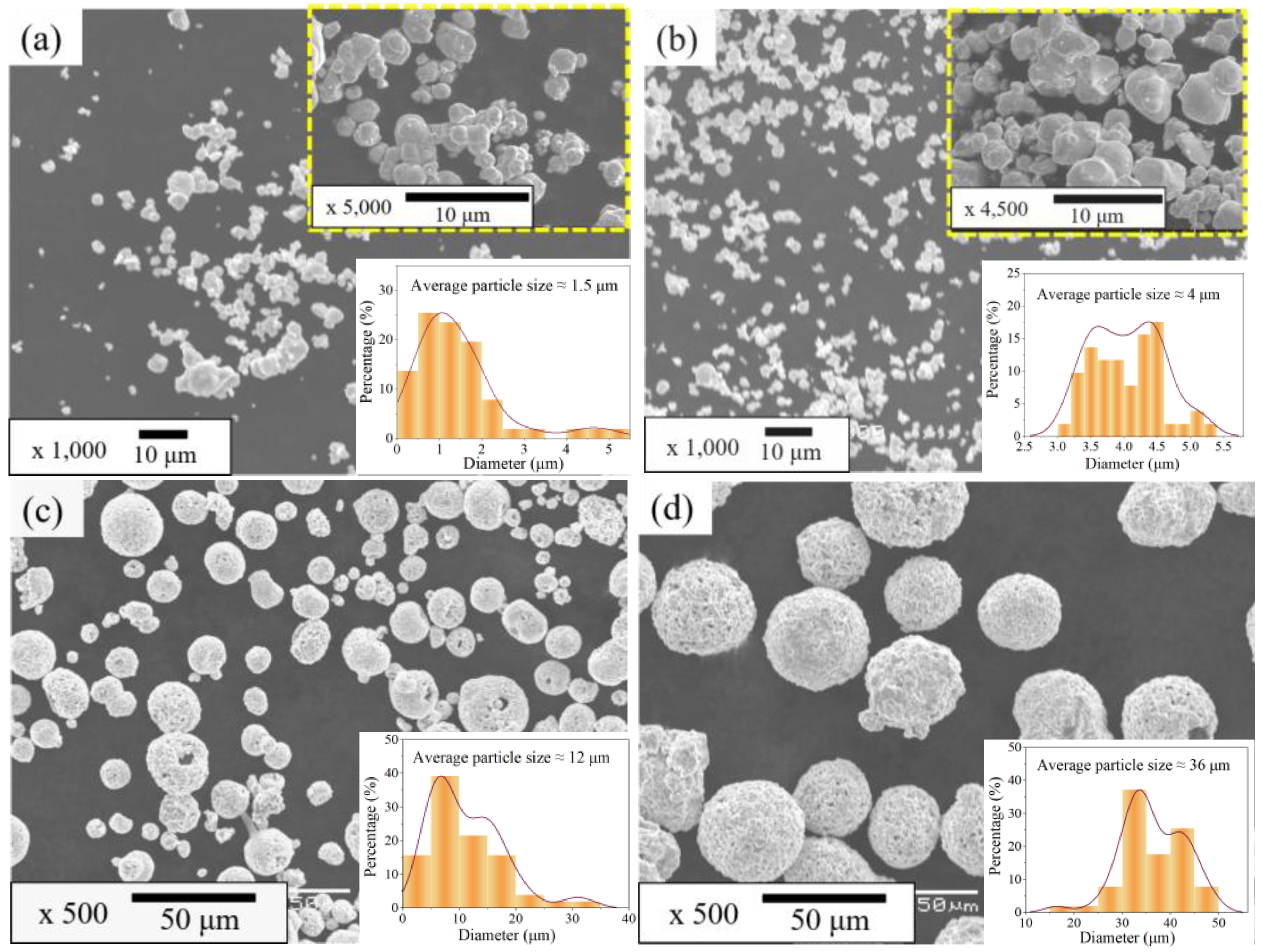
| 50 N | 5 mm | 4 Hz | 25,000 N | 1.5, 4, 12, 36 μm |
Publisher’s Note: MDPI stays neutral with regard to jurisdictional claims in published maps and institutional affiliations. |
© 2022 by the authors. Licensee MDPI, Basel, Switzerland. This article is an open access article distributed under the terms and conditions of the Creative Commons Attribution (CC BY) license (https://creativecommons.org/licenses/by/4.0/).
Share and Cite
Hu, Q.; Ji, D.; Shen, M.; Zhuang, H.; Yao, H.; Zhao, H.; Guo, H.; Zhang, Y. Three-Body Abrasive Wear Behavior of WC-10Cr3C2-12Ni Coating for Ball Mill Liner Application. Materials 2022, 15, 4569. https://doi.org/10.3390/ma15134569
Hu Q, Ji D, Shen M, Zhuang H, Yao H, Zhao H, Guo H, Zhang Y. Three-Body Abrasive Wear Behavior of WC-10Cr3C2-12Ni Coating for Ball Mill Liner Application. Materials. 2022; 15(13):4569. https://doi.org/10.3390/ma15134569
Chicago/Turabian StyleHu, Qiang, Dehui Ji, Mingxue Shen, Hui Zhuang, Hailong Yao, Huoping Zhao, Hui Guo, and Youliang Zhang. 2022. "Three-Body Abrasive Wear Behavior of WC-10Cr3C2-12Ni Coating for Ball Mill Liner Application" Materials 15, no. 13: 4569. https://doi.org/10.3390/ma15134569
APA StyleHu, Q., Ji, D., Shen, M., Zhuang, H., Yao, H., Zhao, H., Guo, H., & Zhang, Y. (2022). Three-Body Abrasive Wear Behavior of WC-10Cr3C2-12Ni Coating for Ball Mill Liner Application. Materials, 15(13), 4569. https://doi.org/10.3390/ma15134569