
Cement-Based Thermoelectric Device for Protection of Carbon Steel in Alkaline Chloride Solution

Abstract
:1. Introduction
2. Materials and Methods
2.1. Synthesis of PANI/MnO2 Composite and Cement-Matrix Composites Containing the PANI/MnO2 Composite
2.2. Thermoelectric Properties of PANI/MnO2 Composite and Cement-Matrix Composites Containing the PANI/MnO2 Composite
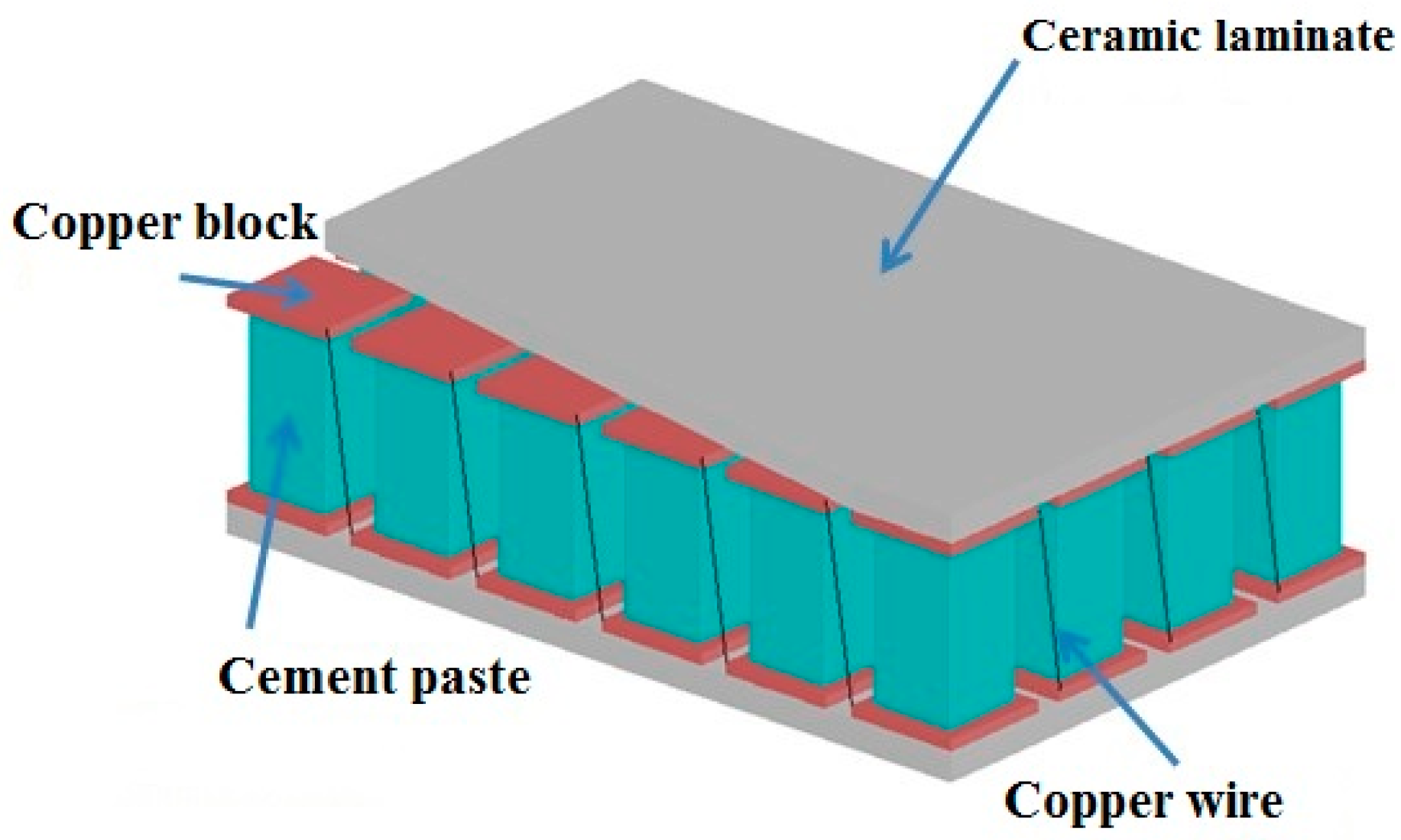
2.3. Preparation of Cement-Based Thermoelectric Device for Cathodic Protection
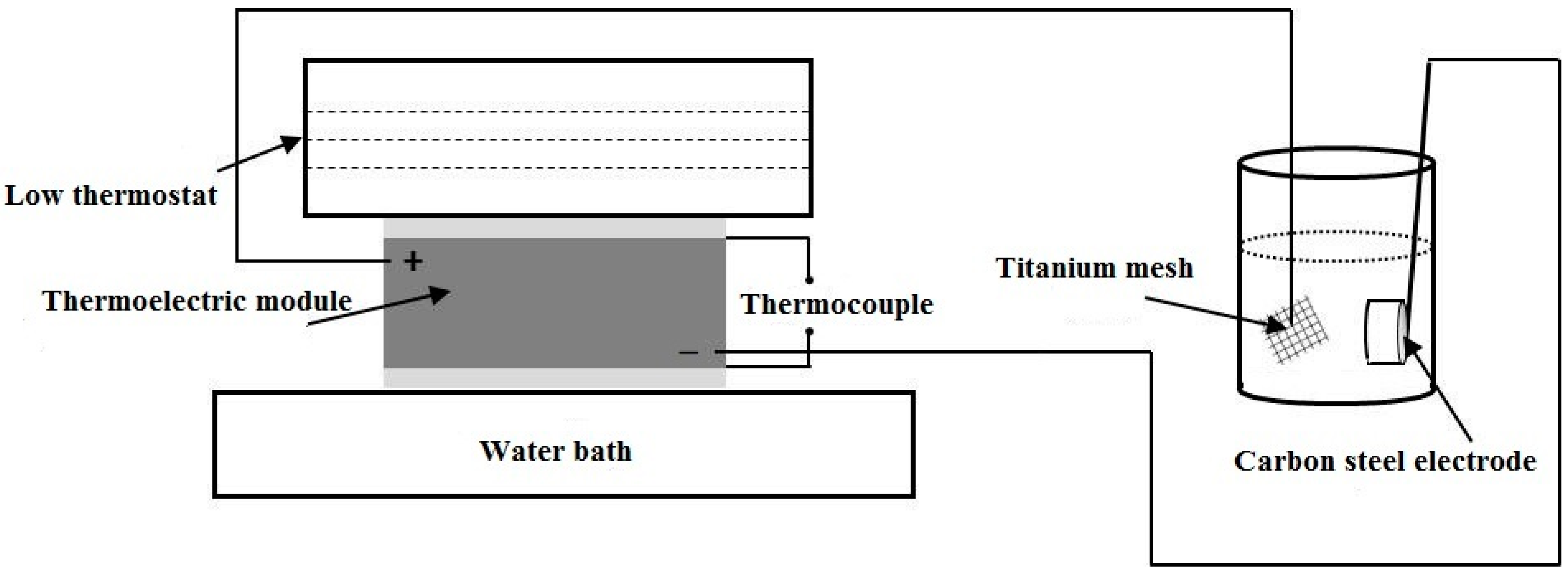
2.4. Electrochemical Experiments
3. Results and Discussion
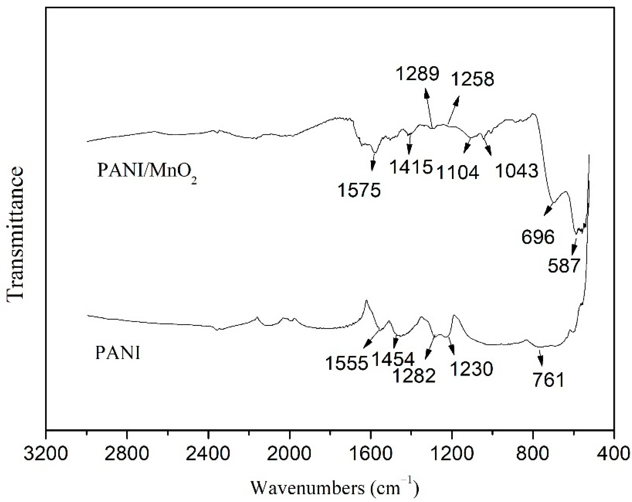
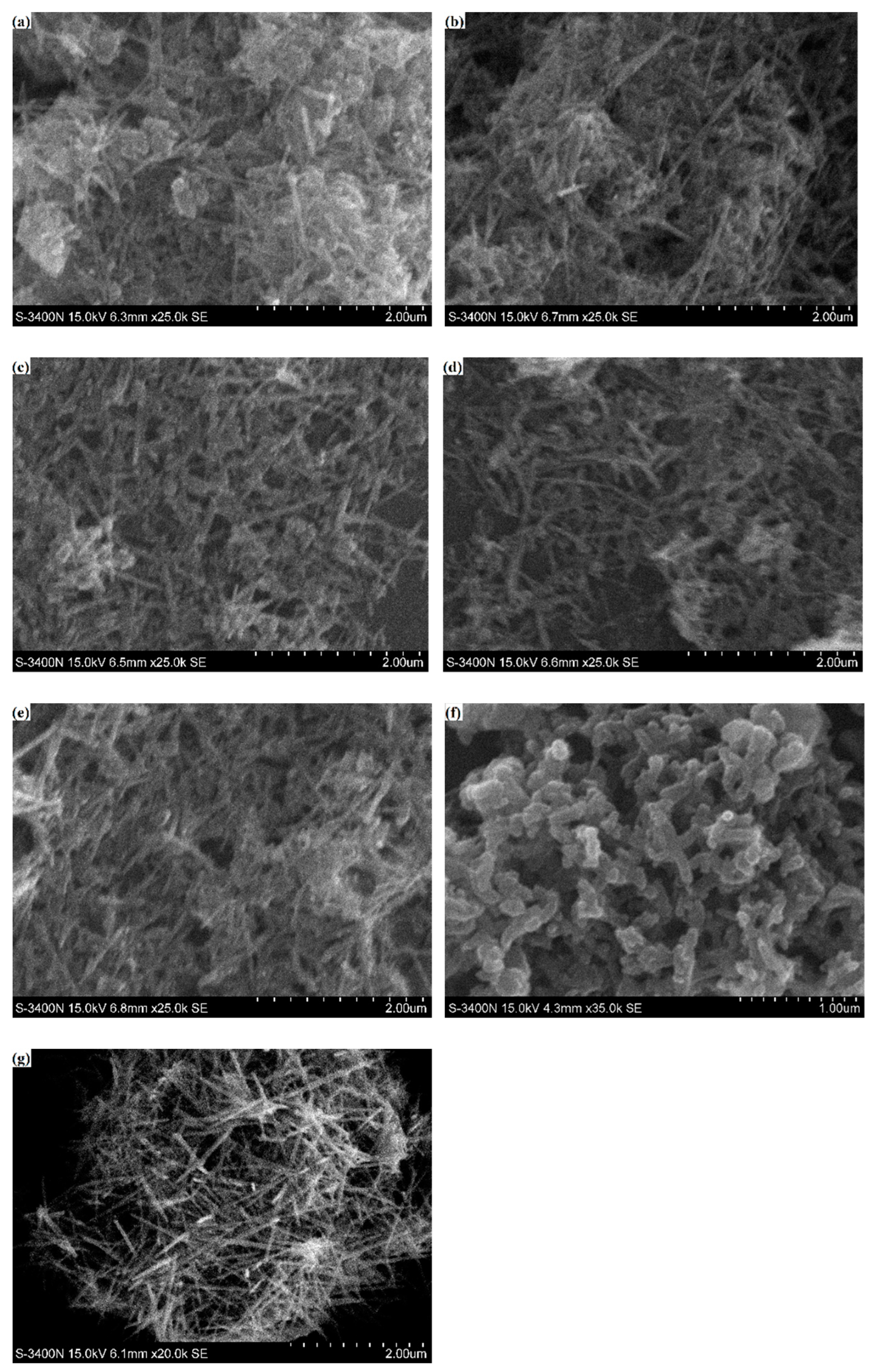
3.1. Characterizations of PANI/MnO2 Composite
3.2. Thermoelectric Properties of PANI/MnO2 Composite and Cement-Matrix Composites Containing the PANI/MnO2 Composite
3.3. Open Circuit Potential (OCP)
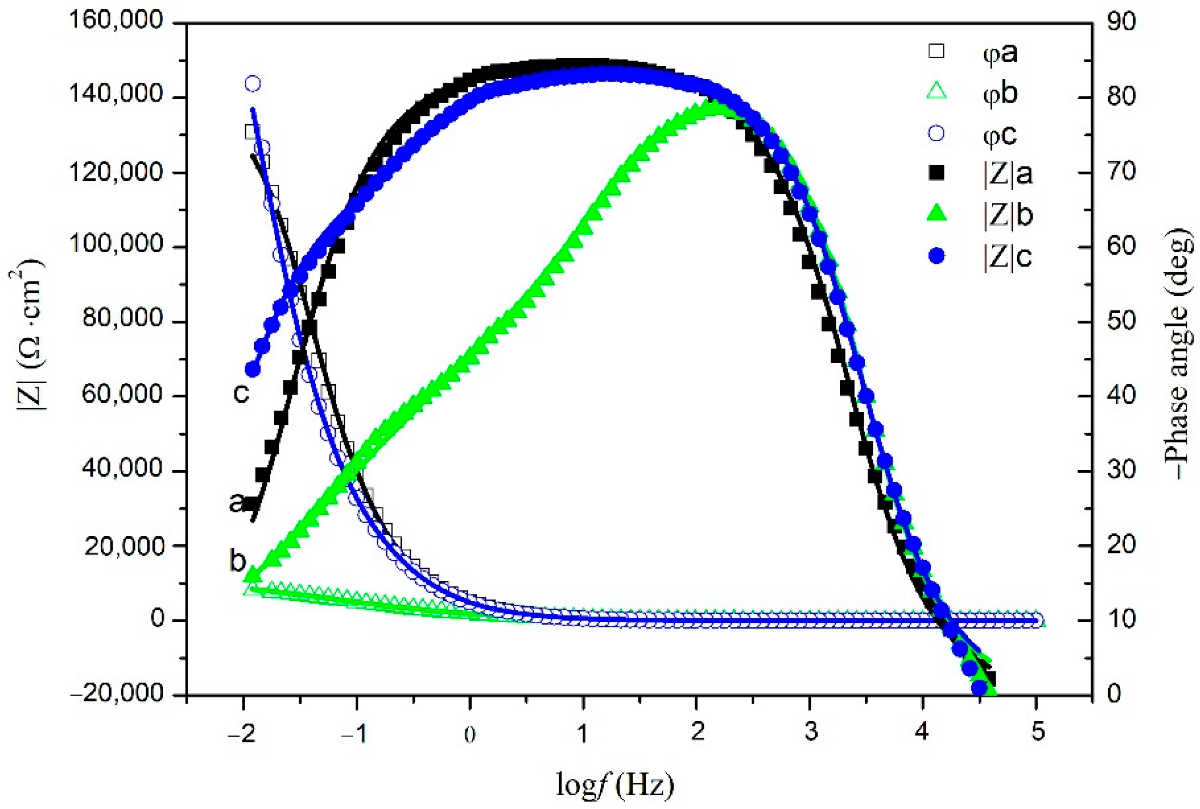
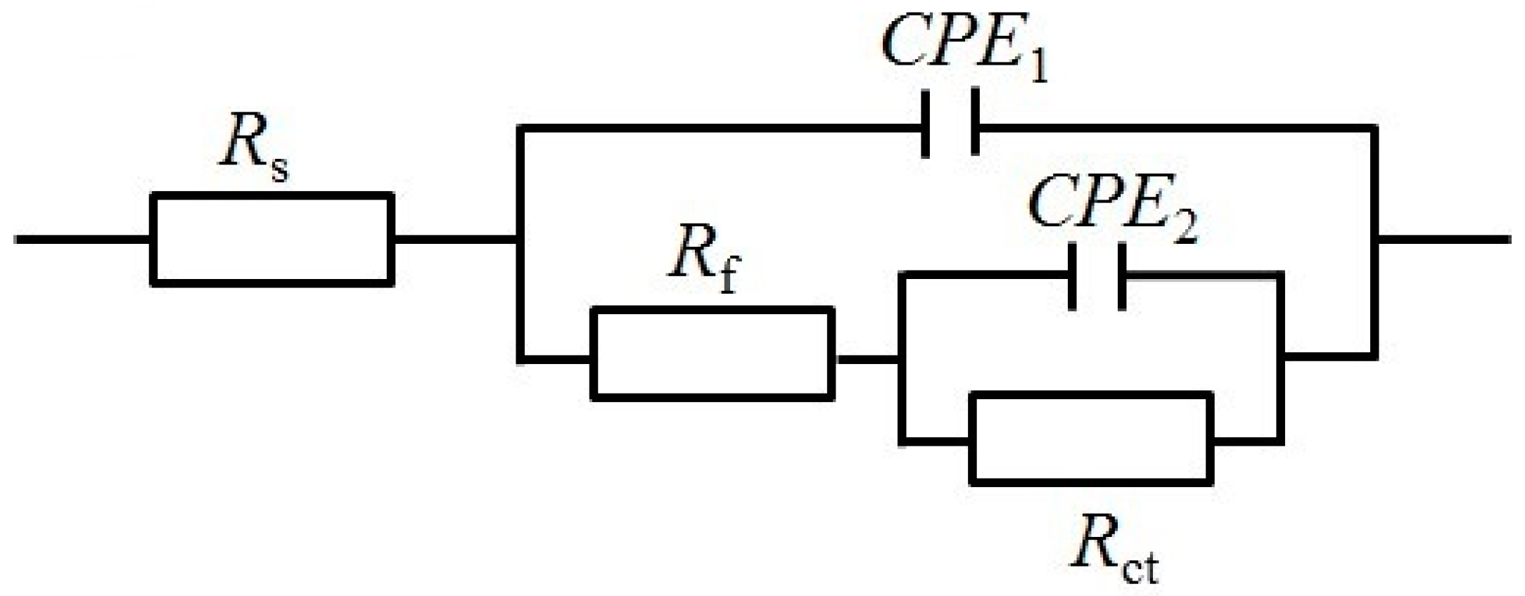
3.4. Electrochemical Impedance Spectroscopy (EIS)
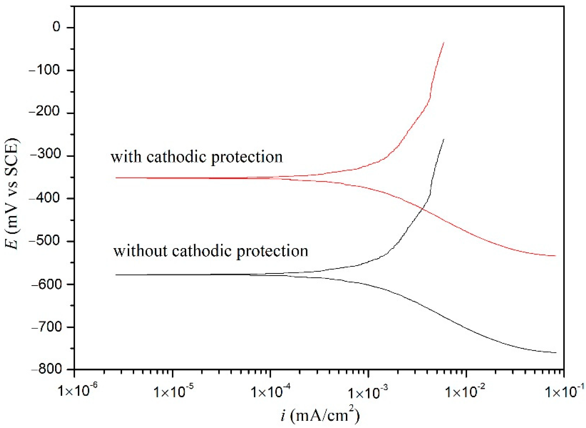
3.5. Polarization Potentiodynamics (PP)
4. Conclusions
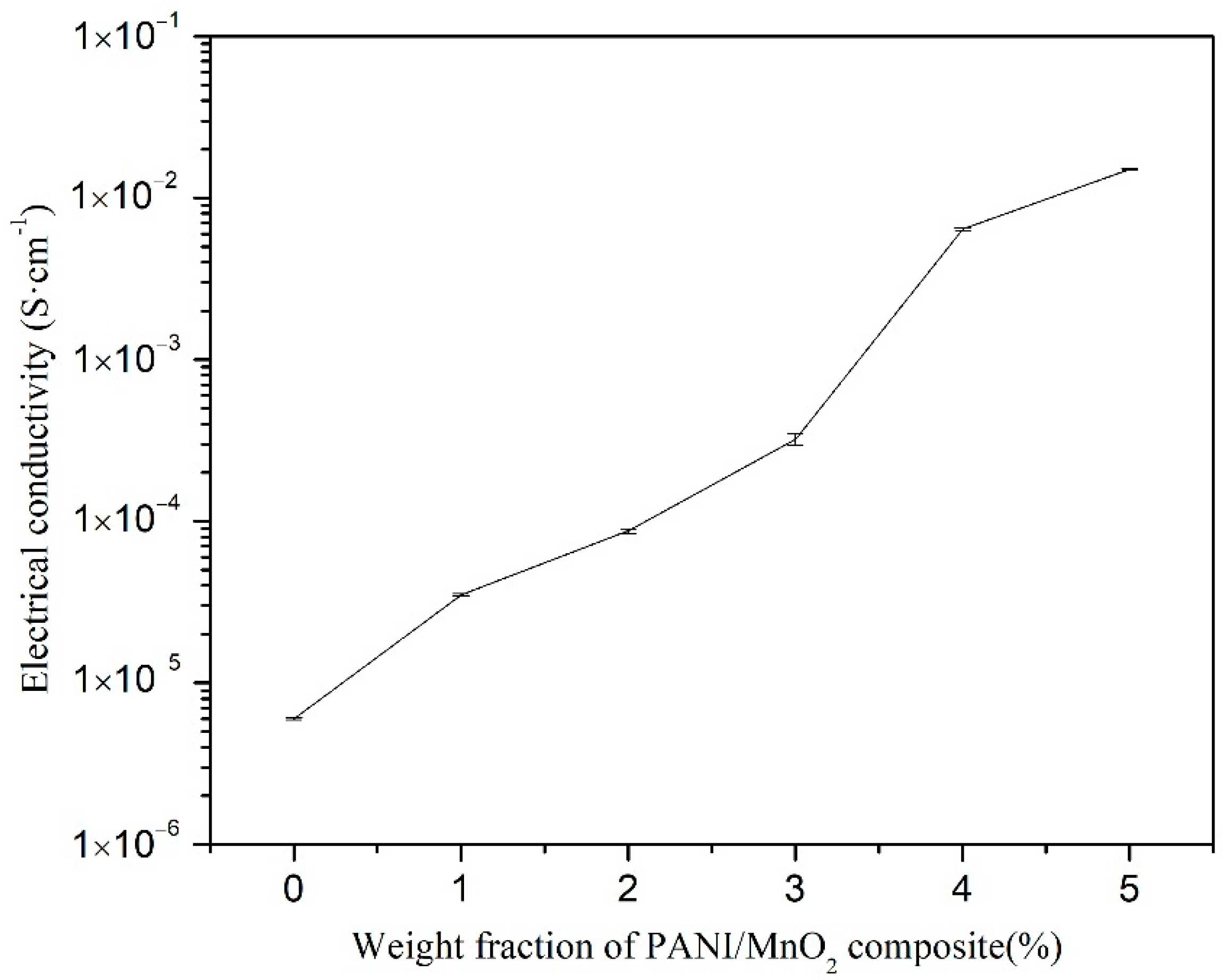
- The PANI is deposited on the surface of the MnO2 particles, providing the PANI/MnO2 composite with good electrical conductivity because of the decrease in the electron conduction path, thereby increasing the electrical conductivity of cement composites with added PANI/MnO2 composite.
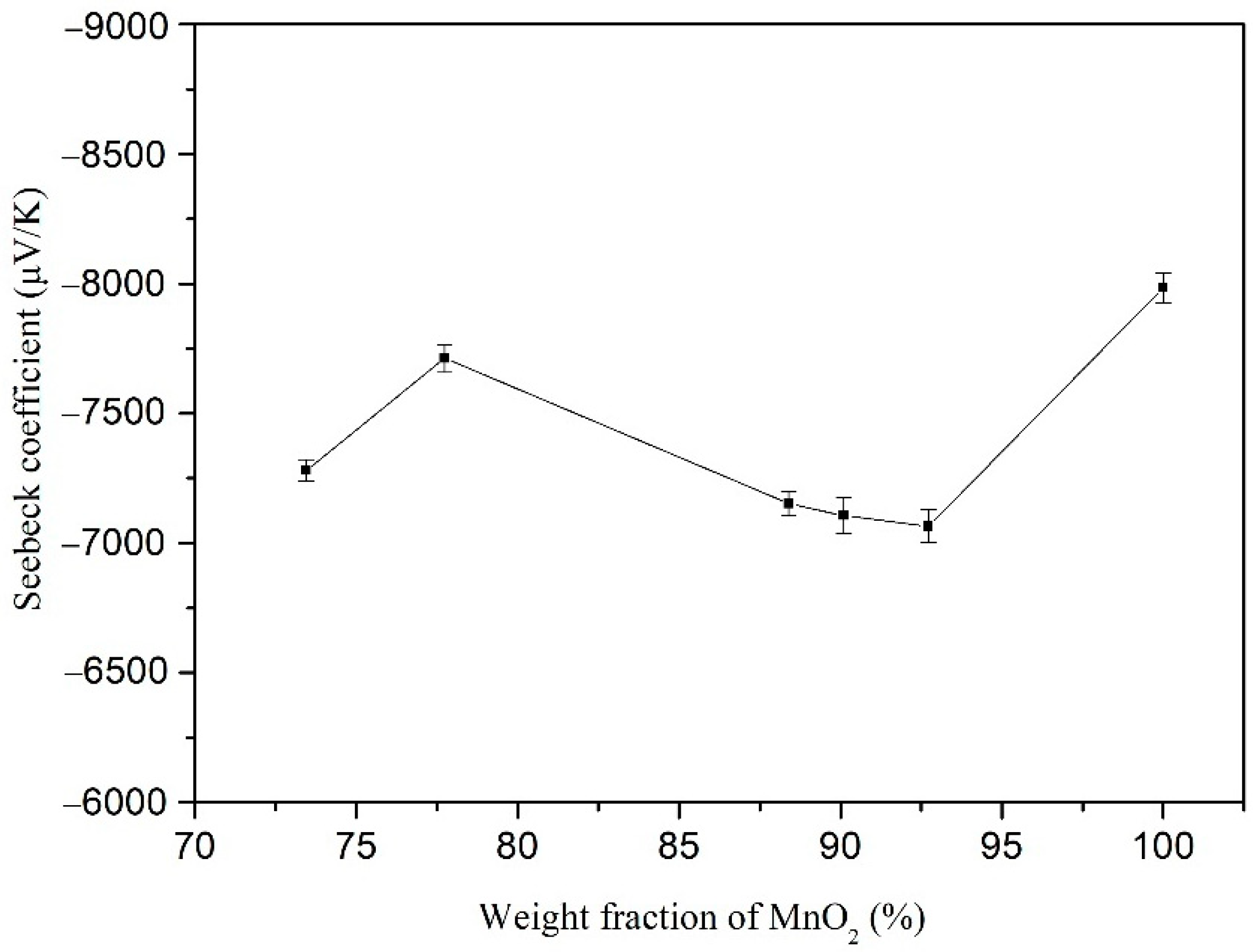
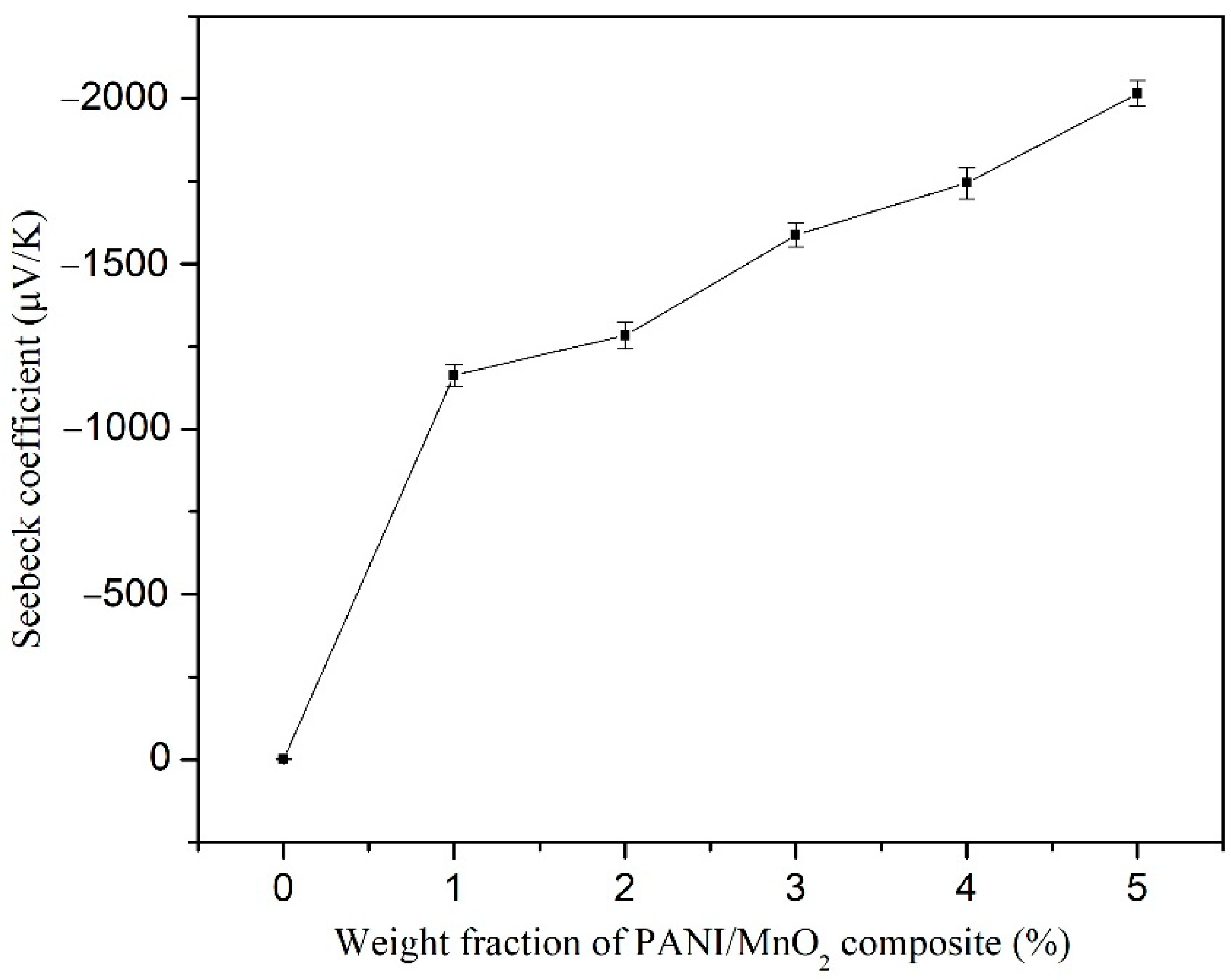
- The nanostructured MnO2 particles provided the PANI/MnO2 composite with large Seebeck coefficient, because of the enhanced gradient of the density of states relative to the energy near the Fermi energy, thereby increasing the Seebeck coefficient of cement composites.
- The decreased open circuit potential, increased charge transfer resistance, and decreased corrosion circuit density demonstrated that the carbon steel immersed in NSCS was effectively protected by the cement-based thermoelectric device.
- In the light of the protection effect, the cement-based thermoelectric-device-driven cathodic protection for reinforced concrete structures suffering chloride corrosion becomes possible.
Author Contributions
Funding
Institutional Review Board Statement
Informed Consent Statement
Data Availability Statement
Conflicts of Interest
References
- Marcos-Meson, V.; Michela, A.; Solgaard, A.; Fischer, G.; Edvardsen, C.; Skovhus, T.L. Corrosion resistance of steel fibre reinforced concrete—A literature review. Cem. Concr. Res. 2018, 103, 1–20. [Google Scholar] [CrossRef] [Green Version]
- Liu, X.; Wang, J.; Hu, W. Facile synthesis of novel hierarchical core@ shell structural magnetic nanovehicle Fe3O4@ ZnAlCe-MoO4-LDHs for carbon steel protection. J. Magn. Magn. Mater. 2021, 523, 167576. [Google Scholar] [CrossRef]
- Feng, R.; Zhang, J.Z.; Zhu, J.H.; Xing, F. Experimental study on the behavior of carbon-fabric reinforced cementitious matrix composites in impressed current cathodic protection. Constr. Build. Mater. 2020, 264, 120655. [Google Scholar] [CrossRef]
- Ackland, B.G.; Dylejko, K.P. Critical questions and answers about cathodic protection. Corros. Eng. Sci. Technol. 2020, 54, 688–697. [Google Scholar] [CrossRef]
- Oleiwi, H.M.; Wang, Y.; Curioni, M.; Chen, X.Y.; Yao, G.W.; Augusthus-Nelson, L.; Ragazzon-Smith, A.H.; Shabalin, I. An experimental study of cathodic protection for chloride contaminated reinforced concrete. Mater. Struct. 2018, 51, 148. [Google Scholar] [CrossRef] [Green Version]
- Hassanein, A.M.; Glass, G.K.; Buenfeld, N.R. Intermittent cathodic protection of concrete structures. In Proceedings of the Fourth International Symposium, Cambridge, UK, 1–4 July 1996; pp. 407–414. [Google Scholar]
- Christodoulou, C.; Glass, G.; Webb, J.; Austin, S.; Goodier, C. Assessing the long term benefits of Impressed Current Cathodic Protection. Corros. Sci. 2010, 52, 2671–2679. [Google Scholar] [CrossRef] [Green Version]
- Yezhov, V.; Semicheva, N.; Pakhomova, E.; Burtsev, A.; Brezhnev, A.; Perepelitsa, N. Characterization of thermoelectric generators for cathodic protection of pipelines of the city heating. In Proceedings of the International Scientific Conference Energy Management of Municipal Facilities and Sustainable Energy Technologies EMMFT 2018, Voronezh, Russia, 10–13 December 2018; pp. 670–678. [Google Scholar]
- Sun, M.; Li, Z.; Mao, Q.; Shen, D. Thermoelectric percolation phenomenon in carbon fiber-reinforced concrete. Cem. Concr. Res. 1998, 28, 1707–1712. [Google Scholar] [CrossRef]
- Wen, S.; Chung, D.D.L. Enhancing the Seebeck effect in carbon fiber reinforced cement by using intercalated carbon fibers. Cem. Concr. Res. 2000, 30, 1295–1298. [Google Scholar] [CrossRef]
- Demirel, B.; Yazicioglu, S. Thermoelectric behavior of carbon fiber reinforced lightweight concrete with mineral admixtures. New Carbon Mater. 2008, 23, 21–24. [Google Scholar]
- Wei, J.; Zhang, Q.; Zhao, L.; Hao, L.; Yang, C.L. Enhanced thermoelectric properties of carbon fiber reinforced cement composites. Ceram. Int. 2016, 42, 11568–11573. [Google Scholar] [CrossRef]
- Zuo, J.; Yao, W.; Liu, X.; Qin, J.J. Sensing properties of carbon nanotube-carbon fiber/cement nanocomposites. J. Test. Eval. 2012, 40, 838–843. [Google Scholar] [CrossRef]
- Tzounis, L.; Liebscher, M.; Fuge, R.; Leonhardt, A.; Mechtcherine, V. P- and n-type thermoelectric cement composites with CVD grown p- and n-doped carbon nanotubes: Demonstration of a structural thermoelectric generator. Energy Build. 2019, 191, 151–163. [Google Scholar] [CrossRef]
- Wei, J.; Fan, Y.; Zhao, L.; Xue, F.; Hao, L.; Zhang, Q. Thermoelectric properties of carbon nanotube reinforced cement-based composites fabricated by compression shear. Ceram. Int. 2018, 44, 5829–5833. [Google Scholar] [CrossRef]
- Ghosh, S.; Harish, S.; Rocky, K.A.; Ohtaki, M.; Saha, B.B. Graphene enhanced thermoelectric properties of cement based composites for building energy harvesting. Energy Build. 2019, 202, 109419. [Google Scholar] [CrossRef]
- Ghosh, S.; Harish, S.; Ohtaki, M.; Saha, B.B. Enhanced figure of merit of cement composites with graphene and ZnO nanoinclusions for efficient energy harvesting in buildings. Energy 2020, 198, 117396. [Google Scholar] [CrossRef]
- Wei, J.; Zhao, L.; Zhang, Q.; Nie, Z.B.; Hao, L. Enhanced thermoelectric properties of cement-based composites with expanded graphite for climate adaptation and large-scale energy harvesting. Energy Build. 2018, 159, 66–74. [Google Scholar] [CrossRef]
- Wei, J.; Hao, L.; He, G.; Yang, C.L. Thermoelectric power of carbon fiber reinforced cement composites enhanced by Ca3Co4O9. In Proceedings of the China Functional Materials Technology and Industry Forum, Kunming, China, 9–12 November 2012; pp. 354–357. [Google Scholar]
- Wei, J.; Hao, L.; He, G.; Yang, C.L. Enhanced thermoelectric effect of carbon fiber reinforced cement composites by metallic oxide/cement interface. Ceram. Int. 2014, 40, 8261–8263. [Google Scholar] [CrossRef]
- Ghaharia, S.; Ghafaria, E.; Lu, N. Effect of ZnO nanoparticles on thermoelectric properties of cement composite for waste heat harvesting. Constr. Build. Mater. 2017, 146, 755–763. [Google Scholar] [CrossRef]
- Ji, T.; Zhang, X.; Li, W.H. Enhanced thermoelectric effect of cement composite by addition of metallic oxide nanopowders for energy harvesting in buildings. Constr. Build. Mater. 2016, 115, 576–581. [Google Scholar] [CrossRef] [Green Version]
- Ji, T.; Zhang, X.Y.; Zhang, X.; Zhang, Y.J.; Li, W.H. Effect of manganese dioxide nanorods on the thermoelectric properties of cement composites. J. Mater. Civ. Eng. 2018, 30, 04018224. [Google Scholar] [CrossRef]
- Pichanusakorn, P.; Bandaru, P. Nanostructured thermoelectrics. Mater. Sci. Eng. R Rep. 2010, 67, 19–63. [Google Scholar] [CrossRef]
- Lan, Y.; Minnich, A.J.; Chen, G.; Ahn, J.P.; Sung, Y.M. Enhancement of thermoelectric figure-of-merit by a bulk nanostructuring approach. Adv. Funct. Mater. 2010, 20, 357–376. [Google Scholar] [CrossRef]
- Alam, H.; Ramakrishna, S. A review on the enhancement of figure of merit from bulk to nano-thermoelectric materials. Nano Energy 2013, 2, 190–212. [Google Scholar] [CrossRef]
- Tong, T.; Fu, D.; Levander, A.X.; Schaff, W.J.; Pantha, B.N.; Lu, N.; Liu, B.; Ferguson, I.; Zhang, R.; Lin, J.Y.; et al. Suppression of thermal conductivity in InxGa1−xN alloys by nanometer-scale disorder. Appl. Phys. Lett. 2013, 102, 121906. [Google Scholar] [CrossRef] [Green Version]
- Chen, B.; Wu, K.; Yao, W. Conductivity of carbon fiber reinforced cement-based composites. Cem. Concr. Compos. 2004, 26, 291–297. [Google Scholar] [CrossRef]
- Belli, A.; Mobili, A.; Bellezze, T.; Tittarelli, F. Commercial and recycled carbon/steel fibers for fiber-reinforced cement mortars with high electrical conductivity. Cem. Concr. Compos. 2020, 109, 103569. [Google Scholar] [CrossRef]
- Zhang, H.; Wu, X.H.; Wang, X.L. Conductivity mechanism of asphalt concrete with the PANI/PP compound conductive fiber. Mater. Sci. Forum 2011, 689, 69–73. [Google Scholar] [CrossRef]
- Meng, Q.; Chung, D.D.L. Battery in the form of a cement-matrix composite. Cem. Concr. Compos. 2010, 32, 829–839. [Google Scholar] [CrossRef]
- Azarsa, P.; Gupta, R. Electrical resistivity of concrete for durability evaluation: A review. Adv. Mater. Sci. Eng. 2017, 2017, 8453095. [Google Scholar] [CrossRef] [Green Version]
- Pani, L.; Francesconi, L.; Rombi, J.; Mistretta, F.; Sassu, M.; Stochino, F. Effect of parent concrete on the performance of recycled aggregate concrete. Sustainability 2020, 12, 9399. [Google Scholar] [CrossRef]
- Feng, C.; Huang, J.; Yan, P.; Wan, F.; Zhu, Y.; Cheng, H. Preparation and properties of waterborne polypyrrole/cement composites. Materials 2021, 14, 5166. [Google Scholar] [CrossRef] [PubMed]
- Jiang, S.; Zhou, D.; Zhang, L.; Ouyang, J.; Yu, X.; Cui, X.; Han, B. Comparison of compressive strength and electrical resistivity of cementitious composites with different nano- and micro-fillers. Arch. Civ. Mech. Eng. 2018, 18, 60–68. [Google Scholar] [CrossRef]
- Fu, C.; Xie, C.; Liu, J.; Wei, X.; Wu, D. A Comparative Study on the effects of three nano-materials on the properties of cement-based composites. Materials 2020, 13, 857. [Google Scholar] [CrossRef] [PubMed] [Green Version]
- Naveen, A.N.; Selladurai, S. Fabrication and performance evaluation of symmetrical supercapacitor based on manganese oxide nanorods–PANI composite. Mater. Sci. Semicon. Proc. 2015, 40, 468–478. [Google Scholar] [CrossRef]
- Tarmizi, A.A.A.; Harun, M.K.; Lyana, S.N. Effect of modified nano silica on the conductivity and morphology characteristics of oxalic acid-doped polyaniline composites. Int. J. Electrochem. Sci. 2021, 16, 210250. [Google Scholar] [CrossRef]
- Roy, H.S.; Islam, M.M.; Mollah, M.Y.A.; Susan, M.A.B.H. Polyaniline-MnO2 composites prepared in-situ during oxidative polymerization of aniline for supercapacitor applications. Mater. Today 2020, 29, 1013–1019. [Google Scholar] [CrossRef]
- Li, Y.; Xu, Z.Y.; Wang, D.W.; Zhao, J.; Zhang, H.H. Snowflake-like core-shell α-MnO2@ δ-MnO2 for high performance asymmetric supercapacitor. Electrochim. Acta 2017, 251, 344–354. [Google Scholar] [CrossRef]
- Mu, Y.K.; Ruan, C.H.; Li, P.X.; Xu, J.; Xie, Y.B. Enhancement of electrochemical performance of cobalt (II) coordinated polyaniline: A combined experimental and theoretical study. Electrochim. Acta 2020, 338, 135881. [Google Scholar] [CrossRef]
- Zhang, J.; Shu, D.; Zhang, T.; Chen, H.; Zhao, H.; Wang, Y.; Sun, Z.; Tang, S.; Fang, X.; Cao, X. Capacitive properties of PANI/MnO2 synthesized via simultaneous-oxidation route. J. Alloys Compd. 2012, 532, 1–9. [Google Scholar] [CrossRef]
- Jiang, H.; Ma, J.; Li, C. Polyaniline–MnO2 coaxial nanofiber with hierarchical structure for high-performance supercapacitors. J. Mater. Chem. 2012, 22, 16939. [Google Scholar] [CrossRef]
- Wei, J.; Jia, Z.; Wang, Y.; Jiang, Y.; Miao, Z.; Zhou, Y.; Zhang, H. Enhanced thermoelectric performance of low carbon cement-based composites by reduced graphene oxide. Energy Build. 2021, 250, 111279. [Google Scholar] [CrossRef]
- Wei, J.; Wang, Y.; Li, X.; Jia, Z.; Qiao, S.; Jiang, Y.; Zhou, Y.; Miao, Z.; Gao, D.; Zhang, H. Dramatically improved thermoelectric properties by defect engineering in cement-based composites. ACS Appl. Mater. Interfaces 2021, 13, 3919–3929. [Google Scholar] [CrossRef] [PubMed]
- Ghosh, S.; Harish, S.; Ohtaki, M.; Saha, B.B. Thermoelectric figure of merit enhancement in cement composites with graphene and transition metal oxides. Mater. Today Energy 2021, 18, 100492. [Google Scholar] [CrossRef]
- Carraro, P.A.; Maragoni, L.; Paipetis, A.S.; Quaresimin, M.; Tzounis, L.; Zappalorto, M. Prediction of the Seebeck coefficient of thermoelectric unidirectional fibre-reinforced composites. Compos. Part B 2021, 223, 109111. [Google Scholar] [CrossRef]
- Liu, X.; Liao, G.; Zuo, J. Enhanced thermoelectric properties of carbon fiber-reinforced cement composites (CFRCs) utilizing Bi2Te3 with three doping methods. Fuller. Nanotub. Carbon Nanostruct. 2021, 29, 295–303. [Google Scholar] [CrossRef]
- Cubides, Y.; Castaneda, H. Corrosion protection mechanisms of carbon nanotube and zinc-rich epoxy primers on carbon steel in simulated concrete pore solutions in the presence of chloride ions. Corros. Sci. 2016, 109, 145–161. [Google Scholar] [CrossRef] [Green Version]
- Zoltowski, P. On the electrical capacitance of interfaces exhibiting constant phase element behavior. J. Electron. Chem. 1998, 443, 149–154. [Google Scholar] [CrossRef]
- Ji, T.; Ma, F.; Liu, D.; Zhang, X.; Zhang, X.; Luo, Q. Effect of diamino ((2-((2-aminoethyl) amino) ethyl) amino) methanethiol on the corrosion resistance of carbon steel in simulated concrete pore solutions. Int. J. Electrochem. Sci. 2018, 13, 5440–5441. [Google Scholar] [CrossRef]
- Jin, M.; Gao, S.; Jiang, L.; Jiang, Y.; Wu, D.; Song, R.; Wu, Y.; He, J. Continuous monitoring of steel corrosion condition in concrete under drying/wetting exposure to chloride solution by embedded MnO2 sensor. Int. J. Electrochem. Sci. 2018, 13, 719–738. [Google Scholar] [CrossRef]
- Wang, C.L.; Gao, W.; Liu, N.Z.; Xin, Y.; Liu, X.Y.; Wang, X.T.; Tian, Y.; Chen, X.W.; Hou, B.R. Covalent organic framework decorated TiO2 nanotube arrays for photoelectrochemical cathodic protection of steel. Corros. Sci. 2020, 176, 108920. [Google Scholar] [CrossRef]
- Brownlie, F.; Giourntas, L.; Hodgkiess, T.; Palmeira, I.; Odutayo, O.; Galloway, A.M.; Pearson, A. Effect of cathodic protection methods on ferrous engineering materials under corrosive wear conditions. Corros. Eng. Sci Technol. 2020, 55, 480–486. [Google Scholar] [CrossRef]
- Jiang, X.H.; Sun, M.M.; Chen, Z.Y.; Jing, J.P.; Feng, C. High-efficiency photoelectrochemical cathodic protection performance of the TiO2/AgInSe2/In2Se3 multijunction nanosheet array. Corros. Sci. 2020, 176, 108901. [Google Scholar] [CrossRef]
- Lu, Y.; Hu, J.; Li, S.; Tang, W. Active and passive protection of steel reinforcement in concrete column using carbon fibre reinforced polymer against corrosion. Electrochim. Acta 2018, 278, 124–136. [Google Scholar] [CrossRef]
- Andrade, C.; Alonso, C. Test methods for on-site corrosion rate measurement of steel reinforcement in concrete by means of the polarization resistance method. Mater. Struct. 2004, 37, 623–643. [Google Scholar] [CrossRef]


| Mixture | Cement (g) | Fly Ash (g) | Water (g) | Superplasticizer (g) | PANI/MnO2 (g) | PANI/MnO2 Fraction (%) |
|---|---|---|---|---|---|---|
| M1 | 300 | 200 | 150 | 3.0 | 0 | 0 |
| M2 | 300 | 200 | 150 | 3.0 | 5 | 1 |
| M3 | 300 | 200 | 150 | 3.0 | 10 | 2 |
| M4 | 300 | 200 | 150 | 3.0 | 15 | 3 |
| M5 | 300 | 200 | 150 | 3.0 | 20 | 4 |
| M6 | 300 | 200 | 150 | 3.0 | 25 | 5 |
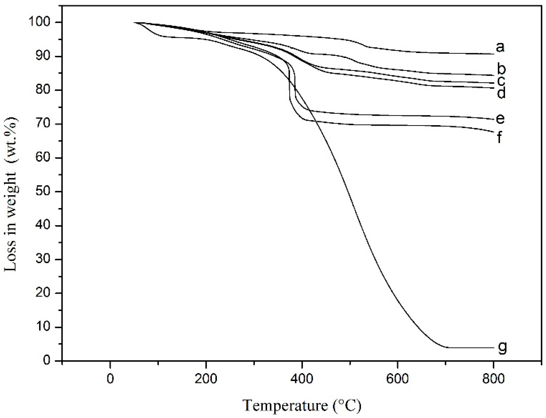
| PANI/ MnO2 Composite | TGA Curve | MnO2 Dosages (g) | PANI Content (wt.%) | MnO2 Content (wt.%) | MnO2 Content (vol.%) |
|---|---|---|---|---|---|
| C1 | b | 4.0 | 26.5 | 73.5 | 30.7 |
| C2 | c | 6.0 | 22.3 | 77.7 | 35.9 |
| C3 | d | 8.0 | 11.6 | 88.4 | 55.0 |
| C4 | e | 10.0 | 10.0 | 90.0 | 59.1 |
| C5 | f | 15.0 | 7.3 | 92.7 | 67.1 |
| Series | Immersion Time (Day) | RS (Ω·cm2) | Cf (μF·cm−2) | n1 | Rf (Ω·cm2) | Cdl (μF·cm−2) | n2 | Rct (kΩ·cm2) |
|---|---|---|---|---|---|---|---|---|
| Without cathodic protection | 0 | 3.60 | 15.66 | 0.990 | 7.33 | 20.53 | 0.872 | 1.46 × 10² |
| 21 | 3.00 | 27.60 | 0.960 | 5.16 × 10² | 175.1 | 0.509 | 11.4 | |
| With cathodic protection | 21 | 2.84 | 35.35 | 0.938 | 5.14 × 10⁴ | 25.87 | 0.768 | 1.98 × 10⁶ |
| Cathodic Protection | Ecorr (mV) | βc (mV/dec) | βa (mV/dec) | icorr (μA/cm2) |
|---|---|---|---|---|
| No | −522.1 | −128 | 303 | 1.67 |
| Yes | −325.5 | −133 | 217 | 0.32 |
Publisher’s Note: MDPI stays neutral with regard to jurisdictional claims in published maps and institutional affiliations. |
© 2022 by the authors. Licensee MDPI, Basel, Switzerland. This article is an open access article distributed under the terms and conditions of the Creative Commons Attribution (CC BY) license (https://creativecommons.org/licenses/by/4.0/).
Share and Cite
Ji, T.; Liao, X.; Zhang, S.; He, Y.; Zhang, X.; Zhang, X.; Li, W. Cement-Based Thermoelectric Device for Protection of Carbon Steel in Alkaline Chloride Solution. Materials 2022, 15, 4461. https://doi.org/10.3390/ma15134461
Ji T, Liao X, Zhang S, He Y, Zhang X, Zhang X, Li W. Cement-Based Thermoelectric Device for Protection of Carbon Steel in Alkaline Chloride Solution. Materials. 2022; 15(13):4461. https://doi.org/10.3390/ma15134461
Chicago/Turabian StyleJi, Tao, Xiao Liao, Shiping Zhang, Yan He, Xiaoying Zhang, Xiong Zhang, and Weihua Li. 2022. "Cement-Based Thermoelectric Device for Protection of Carbon Steel in Alkaline Chloride Solution" Materials 15, no. 13: 4461. https://doi.org/10.3390/ma15134461
APA StyleJi, T., Liao, X., Zhang, S., He, Y., Zhang, X., Zhang, X., & Li, W. (2022). Cement-Based Thermoelectric Device for Protection of Carbon Steel in Alkaline Chloride Solution. Materials, 15(13), 4461. https://doi.org/10.3390/ma15134461