
Bond Behavior of FRP Bars in Lightweight SCC under Direct Pull-Out Conditions: Experimental and Numerical Investigation


Abstract
:1. Introduction
2. Materials and Methods
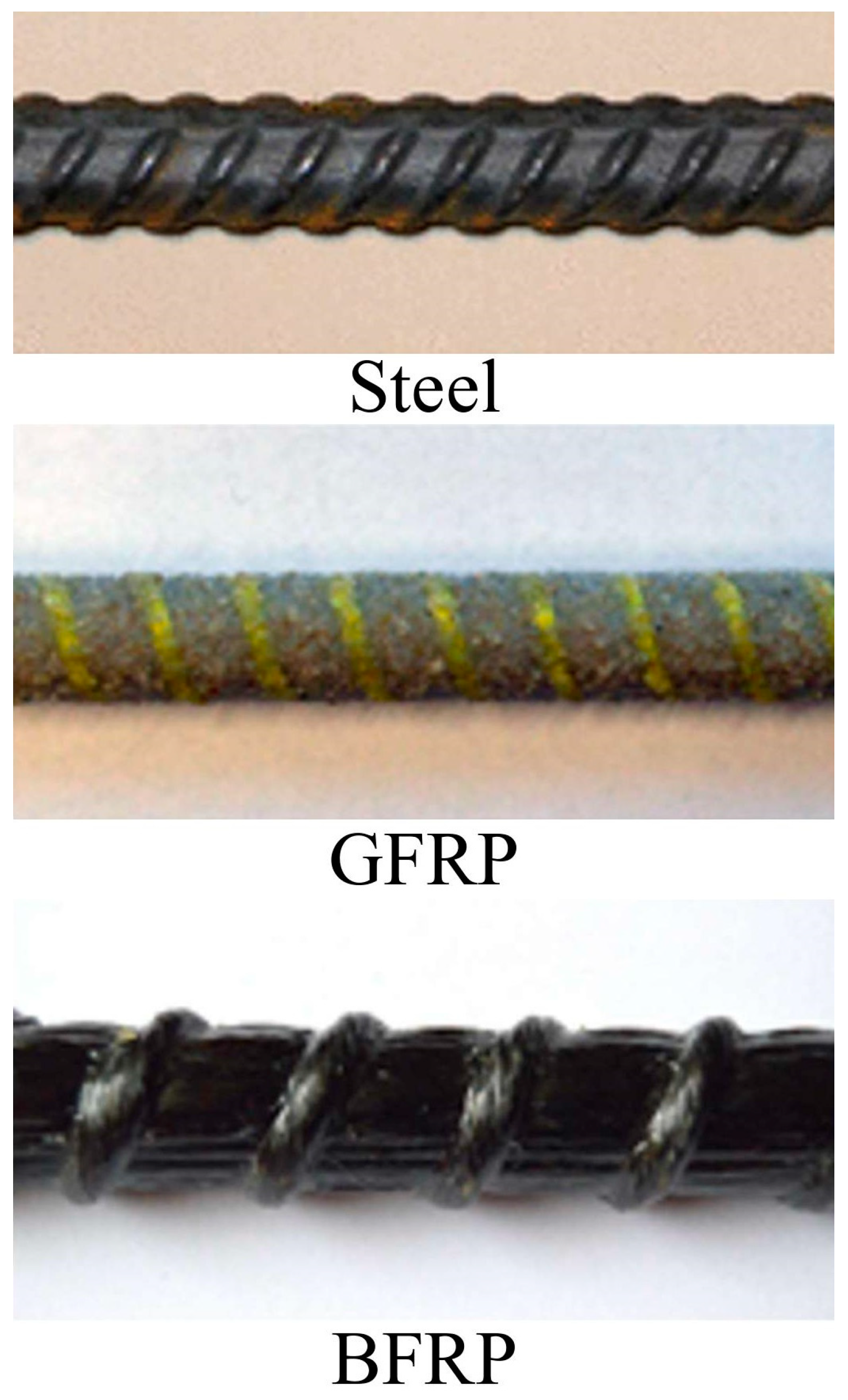
2.1. Materials
2.2. Experimental Methods
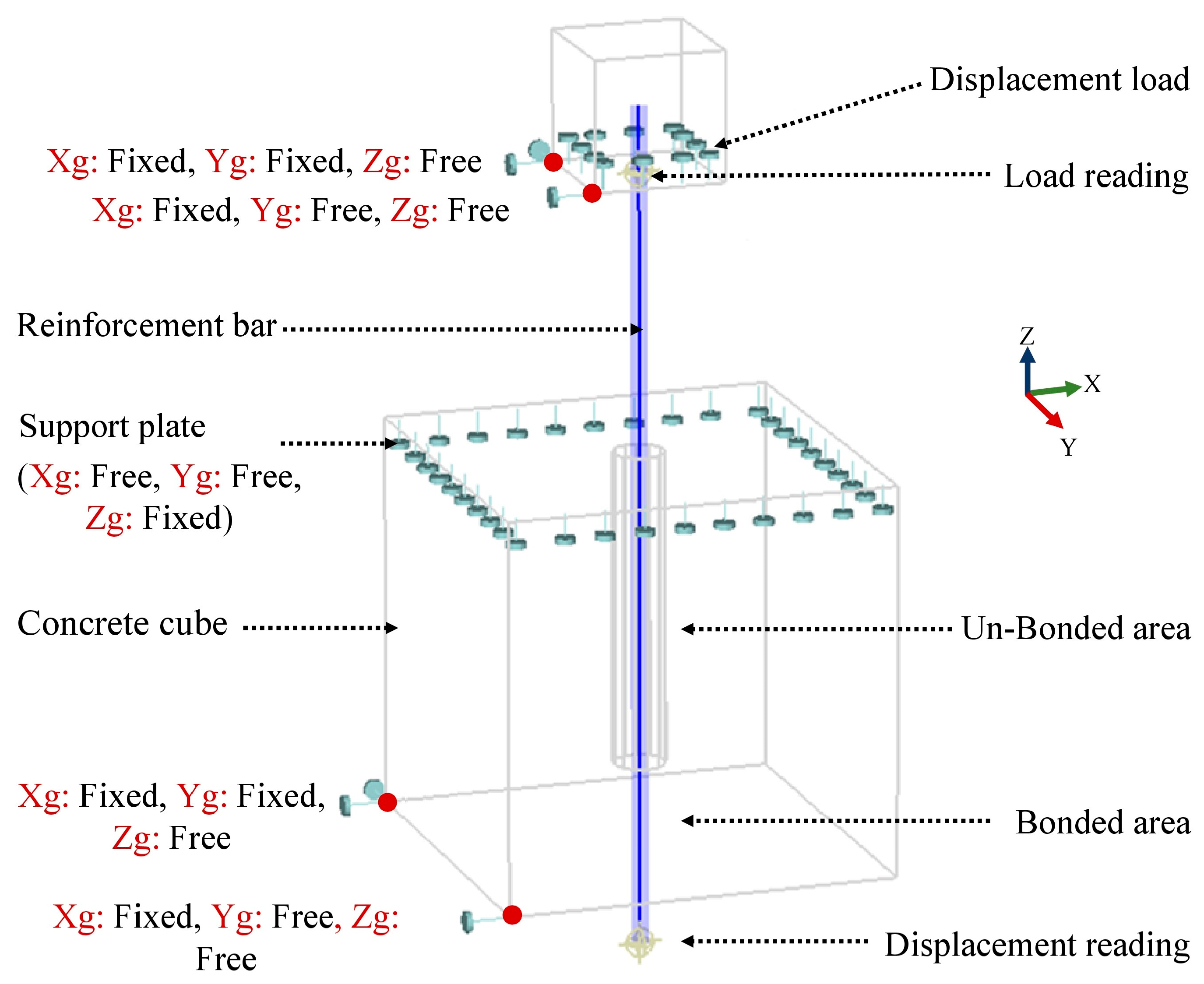
2.3. Computational Modeling
3. Results
3.1. Fresh Properties
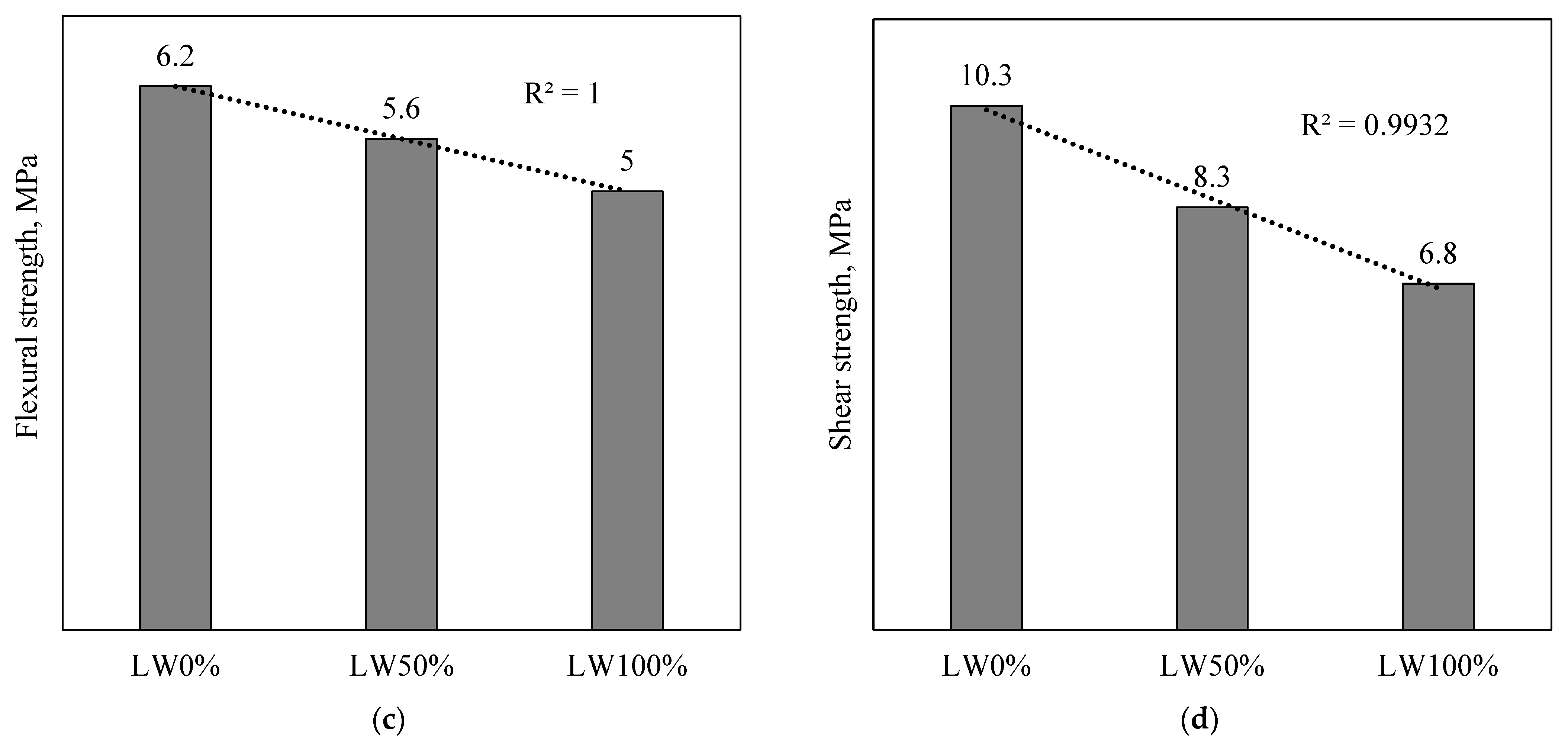
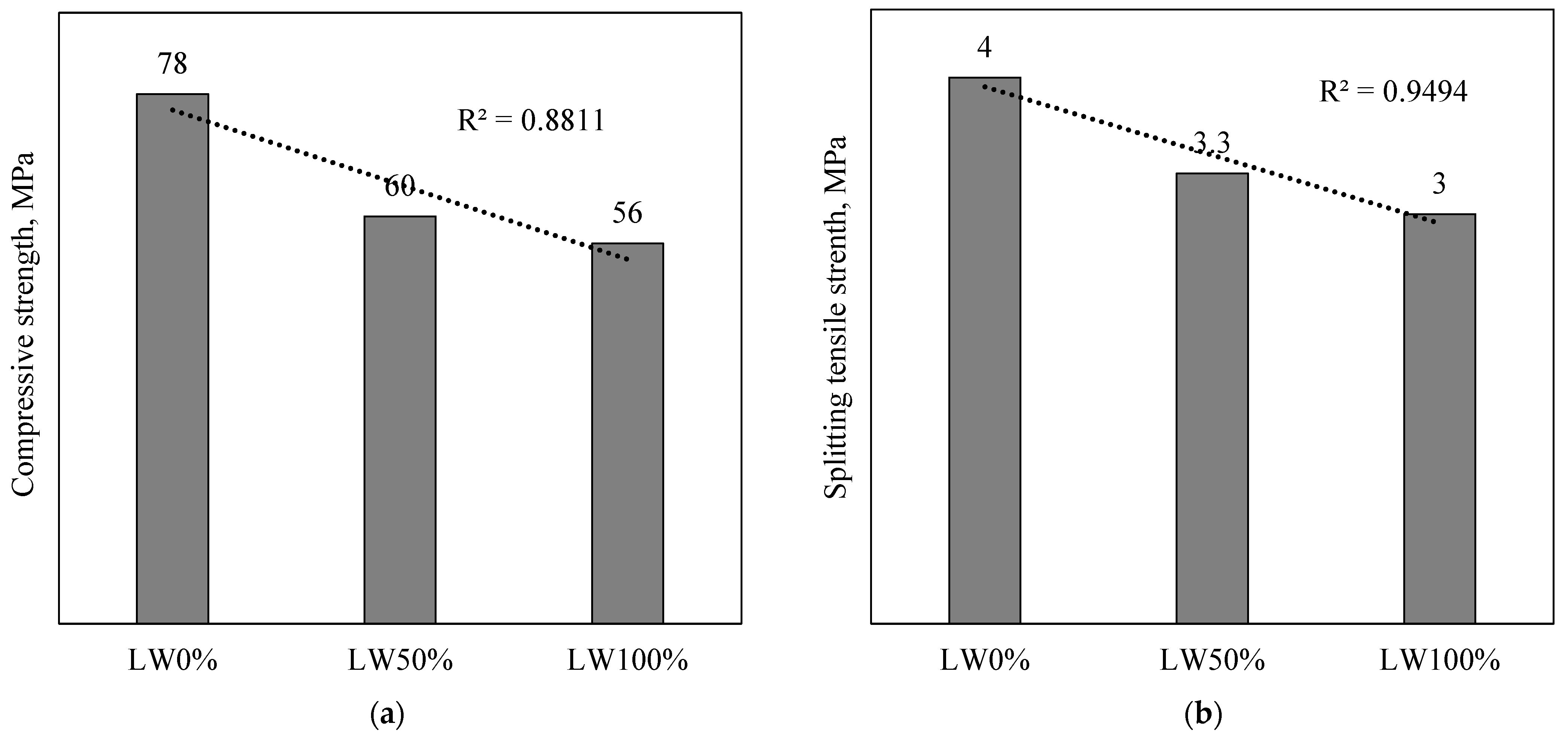
3.2. Mechanical Properties
- Expanded clay has high porosity that increases the water absorption of concrete,
- Increasing the pore area and thickness of the interfacial zone in LWC renders cement particles unable to bind intimately with the expanded clay,
- Expanded clay has a low density and crushing strength, which leads to a reduction in the strength of SCC.

3.3. Schmidt Hammer Rebound Value and Density
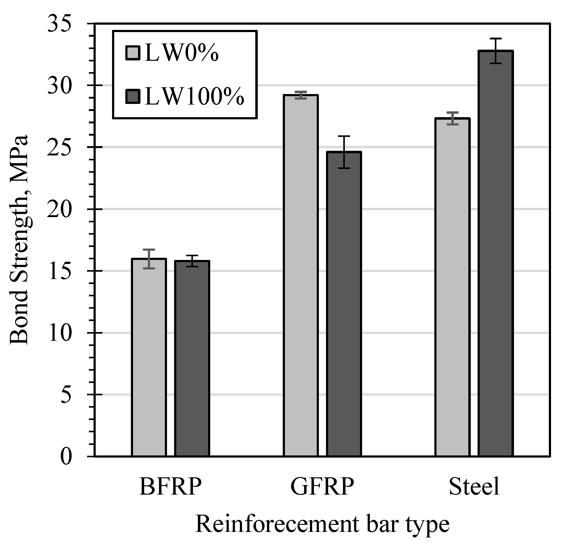
3.4. Pull-Out Test
3.4.1. Experimental Evaluation
3.4.2. Bond Failure Modes
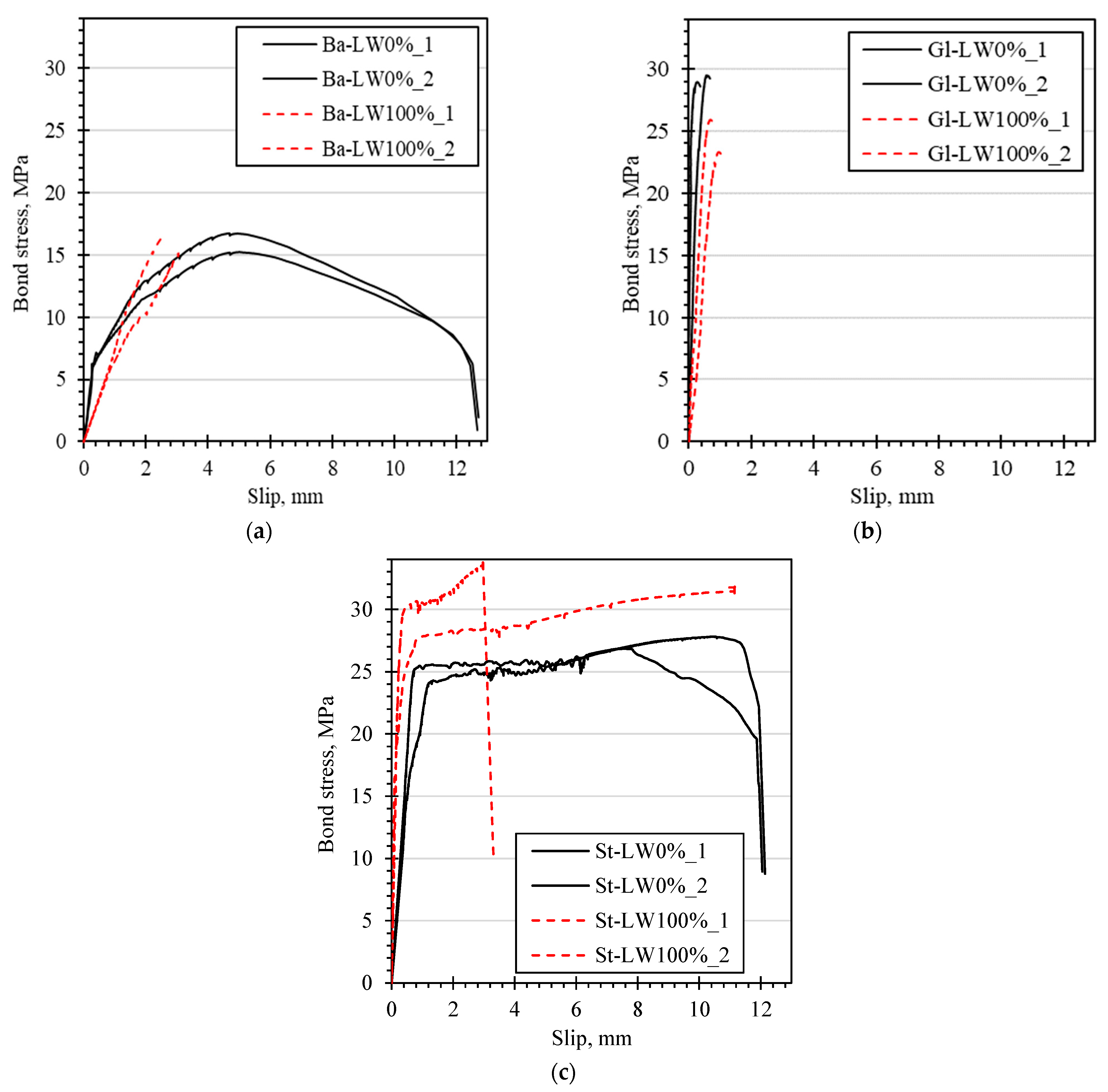
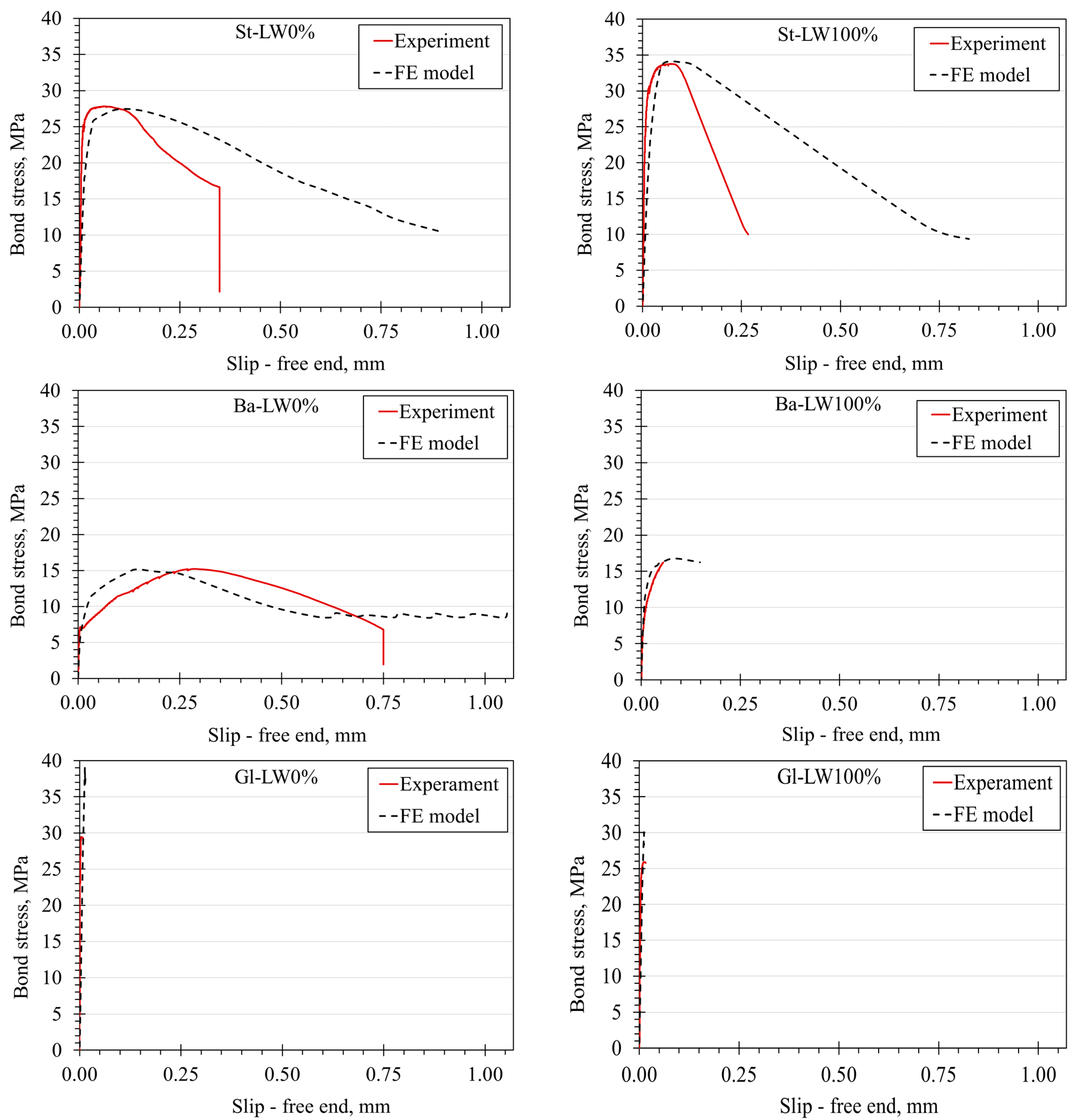
3.4.3. Bond Stress–Slip Relationships
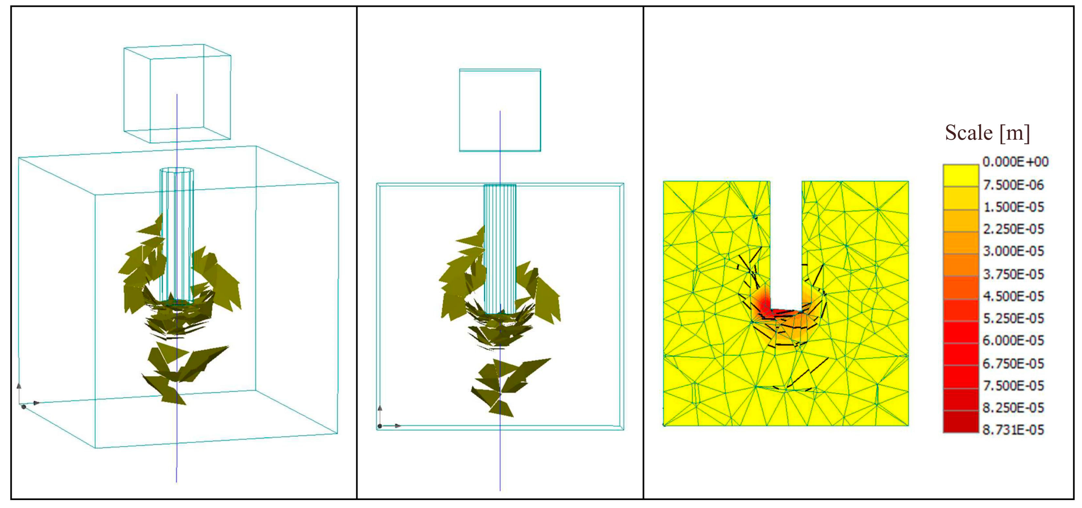
3.5. Numerical Evaluation
4. Conclusions
Supplementary Materials
Author Contributions
Funding
Institutional Review Board Statement
Informed Consent Statement
Data Availability Statement
Conflicts of Interest
References
- De Brito, J.; Kurda, R. The past and future of sustainable concrete: A critical review and new strategies on cement-based materials. J. Clean. Prod. 2021, 281, 72. [Google Scholar] [CrossRef]
- Li, Q.; Zhang, L.Y.; Zhang, L.M.; Jha, S. Exploring multi-level motivations towards green design practices: A system dynamics approach. Sustain. Cities Soc. 2021, 64, 14. [Google Scholar] [CrossRef]
- Barroqueiro, T.; da Silva, P.R.; de Brito, J. High-Performance Self-Compacting Concrete with Recycled Aggregates from the Precast Industry: Durability Assessment. Buildings 2020, 10, 113. [Google Scholar] [CrossRef]
- Abed, M.A.; Tayeh, B.A.; Abu Bakar, B.H.; Nemes, R. Two-Year Non-Destructive Evaluation of Eco-Efficient Concrete at Ambient Temperature and after Freeze-Thaw Cycles. Sustainability 2021, 13, 10605. [Google Scholar] [CrossRef]
- Faraj, R.H.; Ali, H.F.H.; Sherwani, A.F.H.; Hassan, B.R.; Karim, H. Use of recycled plastic in self-compacting concrete: A comprehensive review on fresh and mechanical properties. J. Build. Eng. 2020, 30, 101283. [Google Scholar] [CrossRef]
- Solyom, S.; Di Benedetti, M.; Balázs, G.L. Bond of FRP bars in air-entrained concrete: Experimental and statistical study. Constr. Build. Mater. 2021, 300, 124193. [Google Scholar] [CrossRef]
- Solyom, S.; Balázs, G.L. Analytical and statistical study of the bond of FRP bars with different surface characteristics. Compos. Struct. 2021, 270, 113953. [Google Scholar] [CrossRef]
- Abed, M.A.; Alkurdi, Z.; Kheshfeh, A.; Kovács, T.; Nehme, S. Numerical Evaluation of Bond Behavior of Ribbed Steel Bars or Seven-Wire Strands Embedded in Lightweight Concrete. Period. Polytech. Civ. Eng. 2021, 65, 385–396. [Google Scholar] [CrossRef]
- Alkhrdaji, T.; Fyfe, E.R.; Karbhari, V.M.; Schupack, M.; Bakis, C.E.; Ganjehlou, A.; Korff, J.G.; Scott, D.W.; Balaguru, P.N.; Gee, D.J.; et al. ACI440.3R—Guide Test Methods for Fiber-Reinforced Polymers (FRPs) for Reinforcing or Strengthening Concrete Structures; American Concrete Institute: Farmington Hills, MI, USA, 2004; pp. 1–40. [Google Scholar]
- Sólyom, S.; Balázs, G.L.; Di Benedetti, M.; Guadagnini, M.; Zappa, E. Bond Strength of GFRP Rebars in Concrete at Elevated Temperature. In Proceedings of the Advanced Composites in Construction, Sheffield, UK, 5–7 September 2017. [Google Scholar]
- Mousavi, S.S.; Dehestani, M.; Mousavi, K.K. Bond strength and development length of steel bar in unconfined self-consolidating concrete. Eng. Struct. 2017, 131, 587–598. [Google Scholar] [CrossRef]
- Ding, X.X.; Geng, H.B.; Zhao, M.L.; Chen, Z.; Li, J. Synergistic Bond Properties of Different Deformed Steel Fibers Embedded in Mortars Wet-Sieved from Self-Compacting SFRC. Appl. Sci. 2021, 11, 144. [Google Scholar] [CrossRef]
- Castel, A.; Vidal, T.; Francois, R. Bond and cracking properties of self-consolidating concrete. Constr. Build. Mater. 2010, 24, 1222–1231. [Google Scholar] [CrossRef]
- Trad, A.; Ghanem, H.; Ismail, R. Bond Behaviour of Structural Lightweight Concrete. High Tech Concrete: Where Technology and Engineering Meet. In Proceedings of the 2017 fib Symposium, Maastricht, The Netherlands, 12–14 June 2017. [Google Scholar] [CrossRef]
- Bogas, J.A.; Gomes, M.G.; Real, S. Bonding of steel reinforcement in structural expanded clay lightweight aggregate concrete: The influence of failure mechanism and concrete composition. Constr. Build. Mater. 2014, 65, 350–359. [Google Scholar] [CrossRef]
- Gao, D.Y.; Yan, H.H.; Fang, D.; Yang, L. Bond strength and prediction model for deformed bar embedded in hybrid fiber reinforced recycled aggregate concrete. Constr. Build. Mater. 2020, 265, 120337. [Google Scholar] [CrossRef]
- Larsen, I.L.; Thorstensen, R.T. The influence of steel fibres on compressive and tensile strength of ultra high performance concrete: A review. Constr. Build. Mater. 2020, 256, 119459. [Google Scholar] [CrossRef]
- Qi, A.; Liu, X.H.; Xu, R.J.; Huang, Y.S. Bond behavior of steel reinforcement in concrete containing ferronickel slag and blast furnace slag powder. Constr. Build. Mater. 2020, 262, 120884. [Google Scholar] [CrossRef]
- Wang, J.; Su, H.; Du, J.S. Corrosion Characteristics of Steel Bars Embedded in Recycled Concrete Beams under Static Loads. J. Mater. Civ. Eng. 2020, 32, 04020263. [Google Scholar] [CrossRef]
- Han, S.W.; Zhou, A.; Ou, J.P. Relationships between interfacial behavior and flexural performance of hybrid steel-FRP composite bars reinforced seawater sea-sand concrete beams. Compos. Struct. 2021, 277, 114672. [Google Scholar] [CrossRef]
- Zamora-Castro, S.A.; Salgado-Estrada, R.; Sandoval-Herazo, L.C.; Melendez-Armenta, R.A.; Manzano-Huerta, E.; Yelmi-Carrillo, E.; Herrera-May, A.L. Sustainable Development of Concrete through Aggregates and Innovative Materials: A Review. Appl. Sci. 2021, 11, 629. [Google Scholar] [CrossRef]
- Cadenazzi, T.; Dotelli, G.; Rossini, M.; Nolan, S.; Nanni, A. Cost and environmental analyses of reinforcement alternatives for a concrete bridge. Struct. Infrastruct. Eng. 2020, 16, 787–802. [Google Scholar] [CrossRef]
- Huang, Z.J.; Chen, W.S.; Tran, T.T.; Pham, T.M.; Hao, H.; Chen, Z.Y.; Elchalakani, M. Experimental and numerical study on concrete beams reinforced with Basalt FRP bars under static and impact loads. Compos. Struct. 2021, 263, 113648. [Google Scholar] [CrossRef]
- Alkurdi, Z. Influence of Concrete Compressive Strength on Transfer Length in Pretensioned Concrete Members Using 3D Nonlinear FEM Analysis. In Proceedings of the 6th International Conference on Civil, Structural and Transportation Engineering (ICCSTE’21), Virtually, 17–19 May 2021. [Google Scholar] [CrossRef]
- Smith, M. ABAQUS/Standard User’s Manual; Version 6.9; Dassault Systèmes: Vélizy-Villacoublay, France, 2009. [Google Scholar]
- Cervenka, V.; Jendele, L.; Cervenka, J. Atena Program Documentation Part 1 Theory; Cervenka Consulting: Prague, Czech Republic, 2007. [Google Scholar]
- Yu, H.; Jeong, D. Finite Element Bond Modeling for Indented Wires in Pretensioned Concrete Crossties. In Proceedings of the 2016 Joint Rail Conference, Columbia, SC, USA, 12–15 April 2016. [Google Scholar] [CrossRef] [Green Version]
- Tavares, A.J.; Barbosa, M.P.; Bittencourt, T.N.; Lorrain, M. Bond steel-concrete: Simulation analysis of the pull-out tests and APULOT using the program ATENA. Rev. IBRACON Estrut. Mater. 2014, 7, 138–157. [Google Scholar] [CrossRef]
- Cheung, A.K.; Leung, C.K.; Kabele, P. Finite element study on bond behavior of steel bar and HSCC/HSFRCC. In Proceedings of the 7th International Conference on Fracture Mechanics of Concrete and Concrete Structures, Prague, Czech Republic, 23–28 May 2010. [Google Scholar]
- EFNARC. The European Guidelines for Self-Compacting Concrete, Eur. Guidellins Self Compacting Concrete 63. 2005. Available online: http://www.efnarc.org/pdf/SCCGuidelinesMay2005.pdf (accessed on 12 April 2022).
- BS EN 12390-3; Testing Hardened Concrete. Compressive Strength of Test Specimens. BSI: London, UK, 2009.
- CEN EN 12697-23; Bituminous Mixtures. Test Methods for Hot Mix Asphalt. Part 23: Determination of the Indirect Tensile Strength of Bituminous Specimens. European Committee for Standardization: Brussels, Belgium, 2004.
- BS EN 12390-5; Testing Hardened Concrete. Flexural Strength of Test Specimens. BSI: London, UK, 2009.
- Abed, M.A.; Fořt, J.; Naoulo, A.; Essa, A. Influence of Polypropylene and Steel Fibers on the Performance and Crack Repair of Self-Compacting Concrete. Materials 2021, 14, 5506. [Google Scholar] [CrossRef]
- Windisch, A. A modified pull-out test and new evaluation methods for a more real local bond-slip relationship. Mater. Struct. 1985, 18, 181–184. [Google Scholar] [CrossRef]
- RILEM. RC 6 Bond Test for Reinforcement Steel. 2. Pull-Out Test, 1983, 2nd ed.; RILEM: London, UK, 1994; pp. 218–220. [Google Scholar] [CrossRef]
- Cervenka, J.; Prochazkova, Z.; Sajdlova, T. ATENA Program Documentation Part 11 Troubleshooting Manual; Cervenka Consulting: Prague, Czech Republic, 2017. [Google Scholar]
- Cervenka, J.; Prochazkova, Z.; Sajdlova, T. ATENA Program Documentation Part 4-2 Tutorial for Program ATENA 3D; Cervenka Consulting: Prague, Czech Republic, 2017. [Google Scholar]
- Maghsoudi, A.A.; Mohamadpour, S.; Maghsoudi, M. Mix design and mechanical properties of self compacting light weight concrete. Int. J. Civ. Eng. 2011, 9, 230–236. [Google Scholar]
- Bogas, J.A.; Nogueira, R. Tensile strength of structural expanded clay lightweight concrete subjected to different curing conditions. KSCE J. Civ. Eng. 2014, 18, 1780–1791. [Google Scholar] [CrossRef]
- Nahhab, A.H.; Ketab, A.K. Influence of content and maximum size of light expanded clay aggregate on the fresh, strength, and durability properties of self-compacting lightweight concrete reinforced with micro steel fibres. Constr. Build. Mater. 2020, 233, 117922. [Google Scholar] [CrossRef]
- Carrillo, J.; Lizarazo, J.M.; Bonett, R. Effect of lightweight and low-strength concrete on seismic performance of thin lightly-reinforced shear walls. Eng. Struct. 2015, 93, 61–69. [Google Scholar] [CrossRef]
- Nogueira, C.L. Anti-plane shear strength of plain concrete. Mater. Today Commun. 2020, 24, 101051. [Google Scholar] [CrossRef]
- Aydin, F.; Saribiyik, M. Correlation between Schmidt Hammer and destructive compressions testing for concretes in existing buildings. Sci. Res. Essays 2010, 5, 1644–1648. [Google Scholar] [CrossRef]
- Mesbah, H.A.; Benzaid, R.; Benmokrane, B. Evaluation of bond strength of FRP reinforcing rods in concrete and FE modelling. Int. J. Civ. Eng. Constr. Sci. 2017, 4, 21–41. [Google Scholar]


| Mix | Proportions in kg/m3 | ||||||
|---|---|---|---|---|---|---|---|
| Cement | Fine Aggregate | Coarse Aggregate | Glenium C300 | Glenium 51 | Water | ||
| Natural Sand | Normal Weight Aggregate | LWA | |||||
| 0/4 (mm) | 4/8 (mm) | ||||||
| LW0% | 500 | 785 | 960 | - | 0.75 | 0.75 | 175 |
| LW50% | 500 | 785 | 480 | 232 | 1.50 | 2.00 | 175 |
| LW100% | 500 | 785 | - | 464 | 2.25 | 3.75 | 175 |
| Parameter | Expanded Clay | |
|---|---|---|
| Oven-dry density (kg/m3) | 2620 | 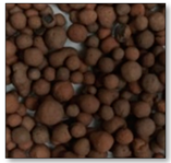 |
| Bulk density (kg/m3) | 359 | |
| Particle density (kg/m3) | 650 | |
| Water absorption (%) | 18.3 | |
| Particle porosity (%) | 75.2 | |
| Crushing resistance (MPa) | 2 |
| Property | Steel B500B | GFRP | BFRP |
|---|---|---|---|
| Tensile strength (MPa) | 540 | 920 | 1100 |
| Yield strength (MPa) | 500 | - | - |
| Modulus of elasticity (MPa) | 200,000 | 55,500 | 70,000 |
| Ultimate strain (%) | 5 | 1.68 | 2.2 |
| Density (kg/m3) | 7850 | 2100 | 1900 |
| Nominal diameter (mm) | 8 | 10 | 14 |
| Consistence Classes Expressed by Slump-Flow | |
| SF1 | When slump flow is 550 to 650 mm |
| SF2 | When slump flow is 660 to 750 mm |
| SF3 | When slump flow is 760 to 850 mm |
| Viscosity Classes Expressed by V-Funnel Time | |
| VF1 | When V-funnel time is ≤8 s |
| VF2 | When V-funnel time is 9 to 25 s |
| Concrete Symbol | Fiber Type | Surface Type | Nominal Diameter | Test No. | Bond Strength | Loaded End Slip | Free End Slip | |||||
|---|---|---|---|---|---|---|---|---|---|---|---|---|
| Fult | Fult a | τb,max | τ a b,max | sle,τb,max | s a le,τb,max | sle,τb,max | s a fe,τb,max | |||||
| mm | kN | kN | MPa | MPa | mm | mm | mm | mm | ||||
| LW0% | BFRP | HW | 14 | 1 | 51.48 | 49.15 | 16.73 | 15.97 | 4.677 | 4.827 | 0.279 | 0.282 |
| 2 | 46.83 | 15.22 | 4.977 | 0.285 | ||||||||
| GFRP | HWSC | 10 | 1 | 46.27 | 45.85 | 29.47 | 29.21 | 0.565 | 0.416 | 0.005 | 0.005 | |
| 2 | 45.44 | 28.94 | 0.267 | NA | ||||||||
| Steel | Ribbed | 8 | 1 | 27.94 | 27.45 | 27.80 | 27.32 | 10.346 | 8.919 | 0.060 | 0.032 | |
| 2 | 26.97 | 26.84 | 7.493 | 0.003 | ||||||||
| LW100% | BFRP | HW | 14 | 1 | 49.98 | 48.63 | 16.24 | 15.80 | 2.467 | 2.79 | 0.056 | 0.06 |
| 2 | 47.28 | 15.36 | 3.109 | 0.055 | ||||||||
| GFRP | HWSC | 10 | 1 | 36.59 | 38.63 | 23.30 | 24.60 | 0.961 | 0.82 | 0.011 | 0.01 | |
| 2 | 40.67 | 25.90 | 0.688 | 0.012 | ||||||||
| Steel | Ribbed | 8 | 1 | 31.94 | 32.94 | 31.78 | 32.79 | 11.150 | 7.06 | 0.765 | 0.42 | |
| 2 | 33.95 | 33.79 | 2.970 | 0.069 | ||||||||
| LW0% | LW100% | ||||
|---|---|---|---|---|---|
| Bond Strength | Slip at the Free End | Bond Strength | Slip at the Free End | ||
| MPa | mm | MPa | Mm | ||
| Steel bar | Experiment | 27.803 | 0.060 | 33.788 | 0.069 |
| FE model | 27.448 | 0.100 | 34.136 | 0.075 | |
| BFRP | Experiment | 15.217 | 0.285 | 16.241 | 0.056 |
| FE model | 15.189 | 0.152 | 16.811 | 0.083 | |
| GFRP | Experiment | 29.470 | 0.005 | 25.902 | 0.011 |
| FE model | 39.130 | 0.013 | 30.010 | 0.012 | |
Publisher’s Note: MDPI stays neutral with regard to jurisdictional claims in published maps and institutional affiliations. |
© 2022 by the authors. Licensee MDPI, Basel, Switzerland. This article is an open access article distributed under the terms and conditions of the Creative Commons Attribution (CC BY) license (https://creativecommons.org/licenses/by/4.0/).
Share and Cite
Abed, M.A.; Alkurdi, Z.; Fořt, J.; Černý, R.; Solyom, S. Bond Behavior of FRP Bars in Lightweight SCC under Direct Pull-Out Conditions: Experimental and Numerical Investigation. Materials 2022, 15, 3555. https://doi.org/10.3390/ma15103555
Abed MA, Alkurdi Z, Fořt J, Černý R, Solyom S. Bond Behavior of FRP Bars in Lightweight SCC under Direct Pull-Out Conditions: Experimental and Numerical Investigation. Materials. 2022; 15(10):3555. https://doi.org/10.3390/ma15103555
Chicago/Turabian StyleAbed, Mohammed A., Zaher Alkurdi, Jan Fořt, Robert Černý, and Sandor Solyom. 2022. "Bond Behavior of FRP Bars in Lightweight SCC under Direct Pull-Out Conditions: Experimental and Numerical Investigation" Materials 15, no. 10: 3555. https://doi.org/10.3390/ma15103555
APA StyleAbed, M. A., Alkurdi, Z., Fořt, J., Černý, R., & Solyom, S. (2022). Bond Behavior of FRP Bars in Lightweight SCC under Direct Pull-Out Conditions: Experimental and Numerical Investigation. Materials, 15(10), 3555. https://doi.org/10.3390/ma15103555