
Cutting Forces in Peripheral Up-Milling of Particleboard


Abstract
1. Introduction
2. Materials and Methods
2.1. Materials
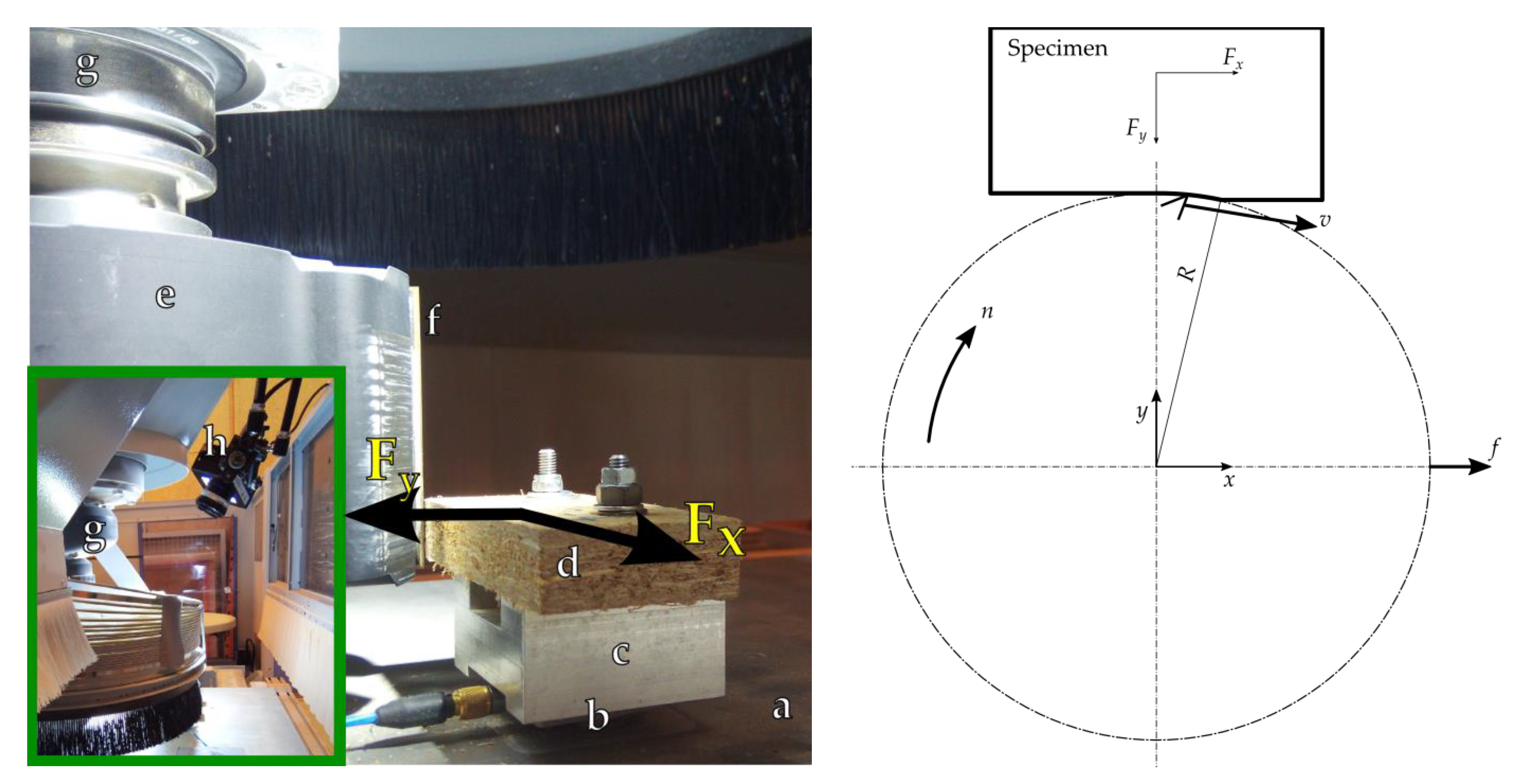
2.2. Machine Tool
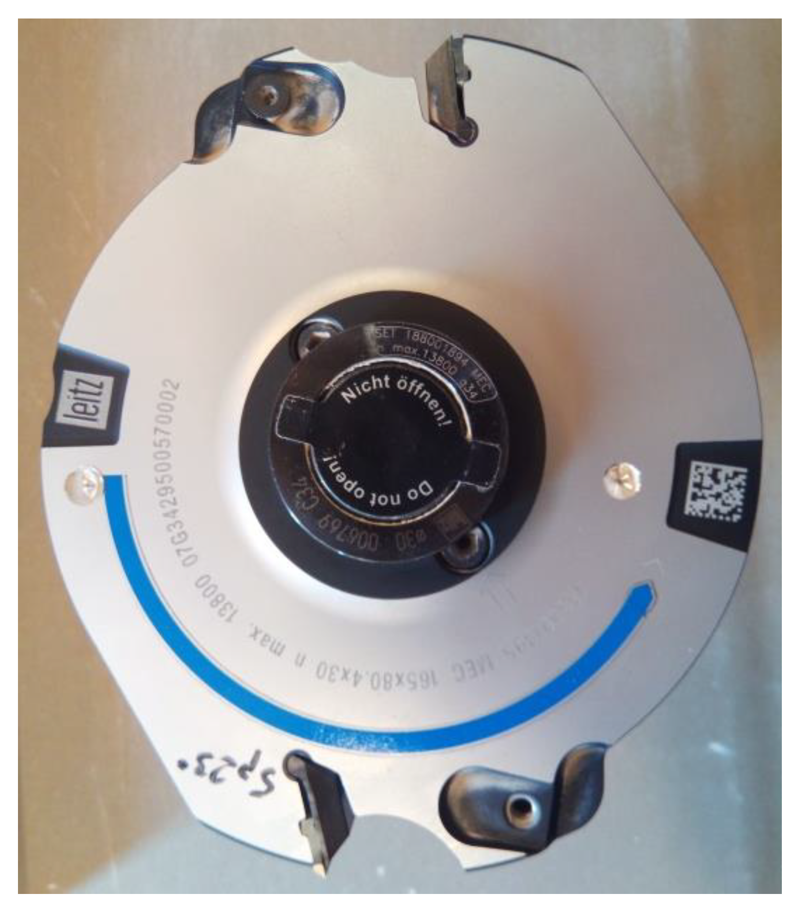
2.3. Cutting Tool
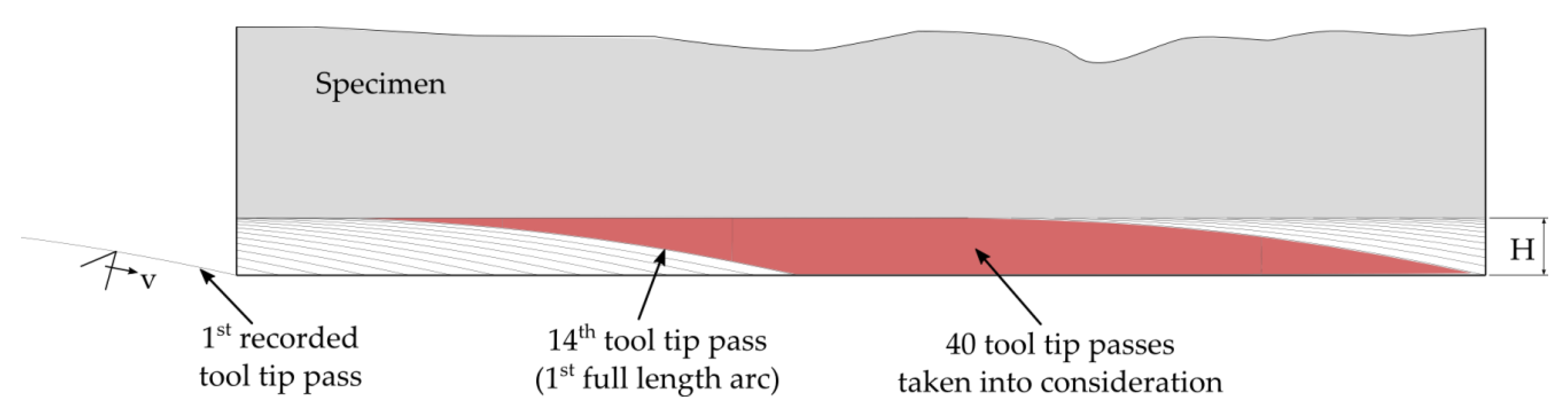
2.4. Machining Process
2.5. The Force Measurement System
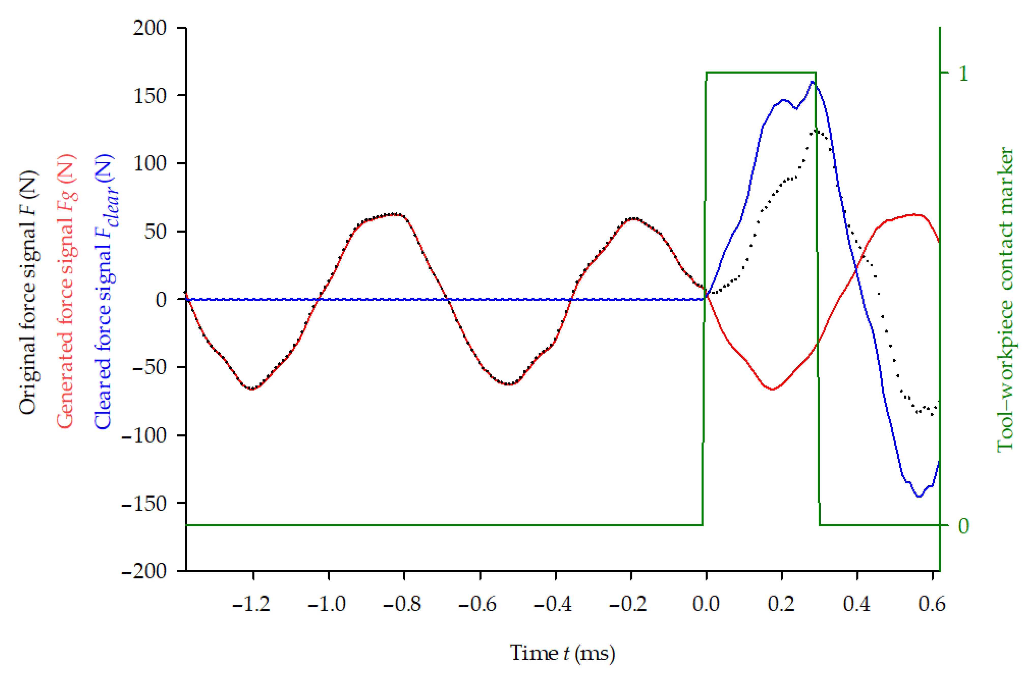
2.6. Force Signal Processing
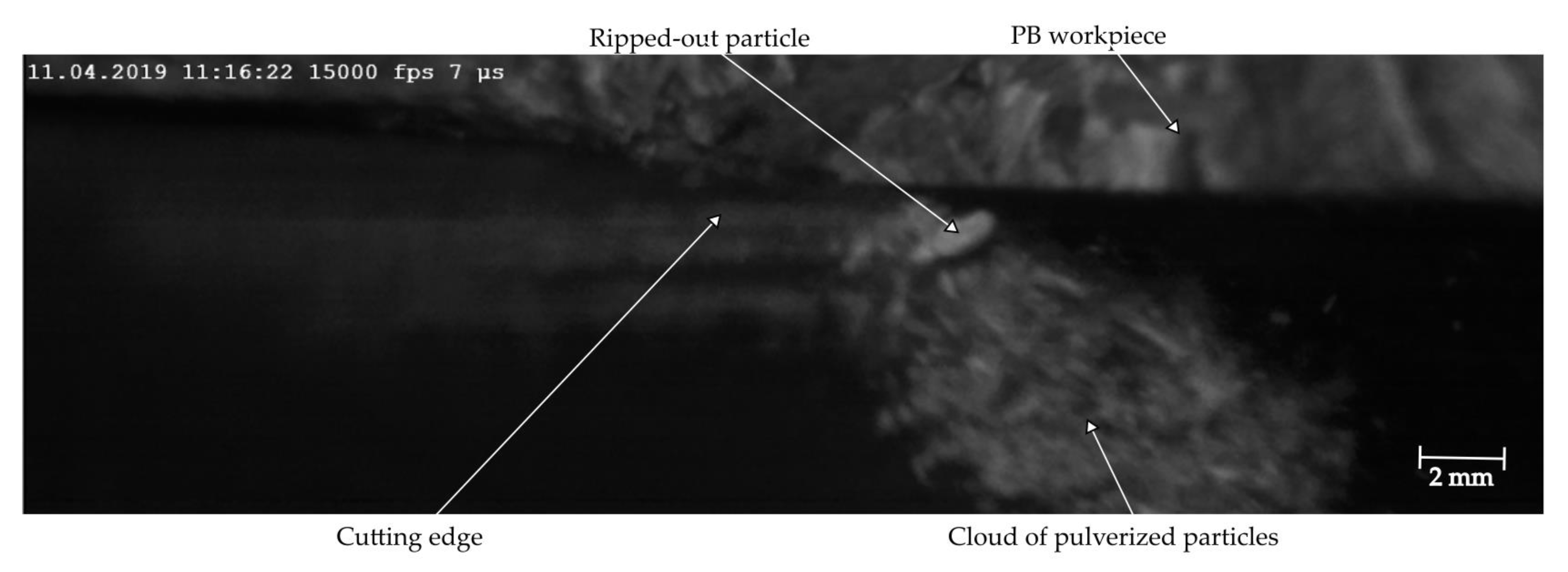
2.7. Vision Control of the Process
3. Results and Discussion
3.1. Resulting Cutting Force
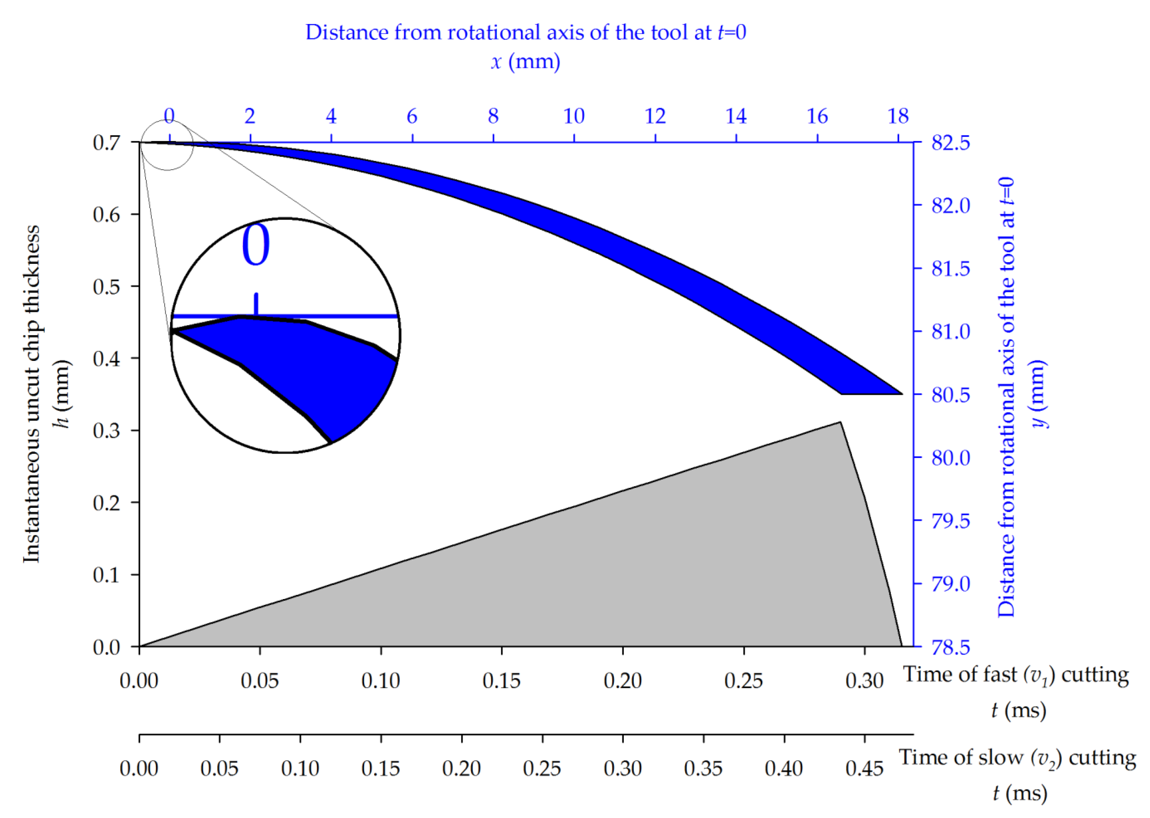
3.2. Instantaneous Uncut Chip Thickness
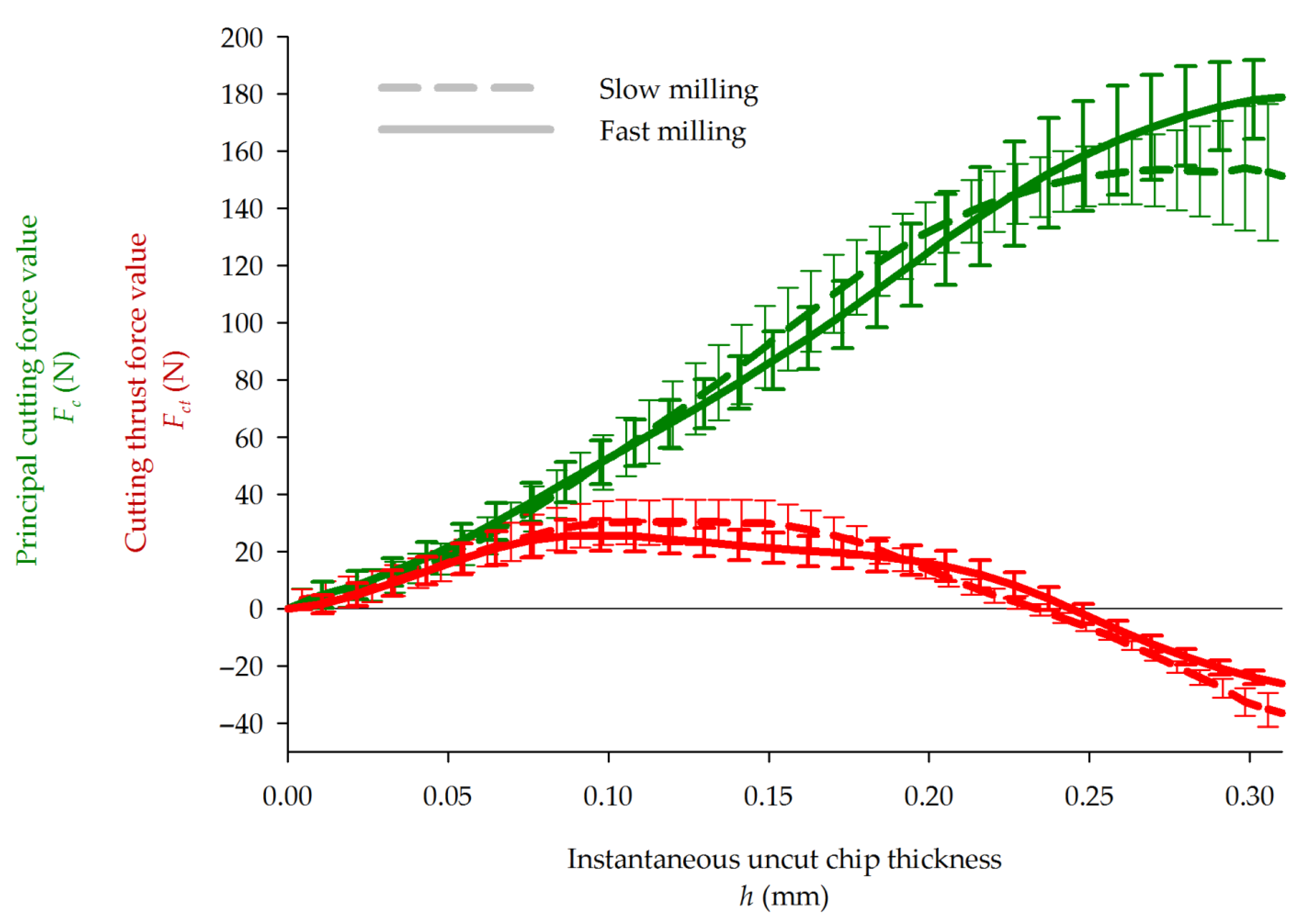
3.3. Principal and Thrust Cutting Forces
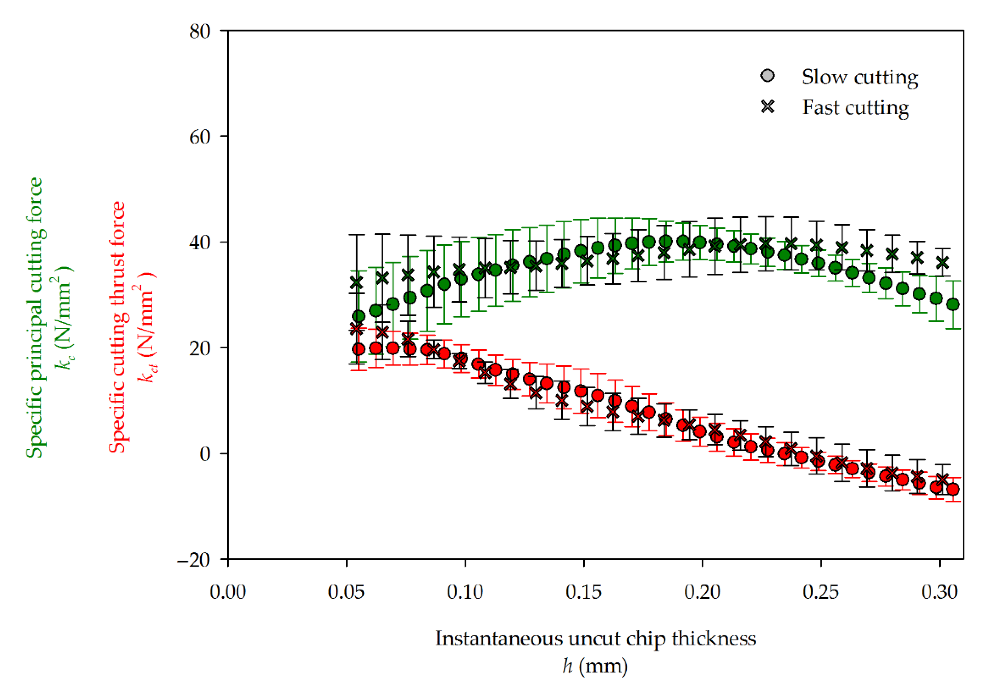
3.4. Specific Cutting Forces
4. Conclusions
Funding
Institutional Review Board Statement
Informed Consent Statement
Data Availability Statement
Acknowledgments
Conflicts of Interest
Nomenclature
| b | mm | Workpiece thickness |
| R | mm | Cutting radius |
| Z | Number of blades in the cutter head | |
| v | m/s | Cutting speed |
| n | min−1 | Rotational speed of the tool |
| fz | mm | Feed per tooth |
| f | m/min | Feed speed |
| H | mm | Depth of cut |
| Hz | Force signal sampling frequency | |
| x, y | mm | Coordinates in perpendicular directions as shown in Figure 2, when they occur as indexes, denote properties in these directions |
| F | N | Force signal (directly measured) |
| N | Discrete Fourier transform of F signal | |
| Fg | N | Signal (imitating the original vibrations) generated in order to clear the F signal |
| N | Force F signal cleared from vibrations | |
| Fr | N | Resultant force |
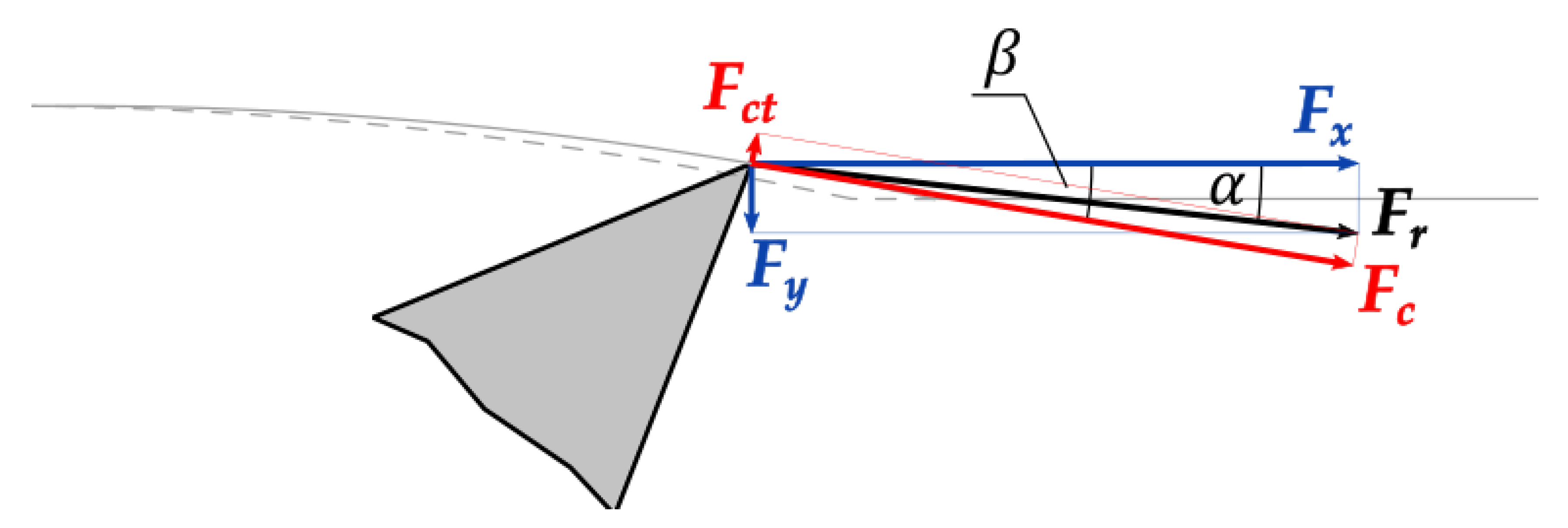
| α | °, rad | Angle between the resultant force and x direction (see Figure 5) |
| N | Principal cutting force | |
| N | Cutting thrust force | |
| t | ms, s | Time |
| mm | Function of tooth path in the workpiece | |
| mm | Function of precedent tooth path function | |
| °, rad | Angle between the cutting force and x direction (see Figure 5) | |
| h | mm | Instantaneous uncut chip thickness (IUCT) |
| kc | N/mm2 | Principal specific cutting force |
| kct | N/mm2 | Specific cutting thrust force |
Abbreviations
| CNC | Computer numerical control |
| PB | Particleboard |
| MDF | Medium density fiberboard |
| IUCT | Instantaneous uncut chip thickness |
References
- Iskra, P.; Tanaka, C.; Ohtani, T. Energy Balance of the Orthogonal Cutting Process. Holz Als Roh Werkst. 2005, 5, 358–364. [Google Scholar] [CrossRef]
- Loehnertz, S.P.; Cooz, I.V. Sawtooth Forces in Cutting Tropical Hardwoods Native to South America. US Department of Agriculture, Forest Service, Forest Products Laboratory, 1998; p. 18. Available online: https://www.srs.fs.usda.gov/pubs/5705 (accessed on 25 April 2021).
- Aguilera, A.; Martin, P. Machining Qualification of Solid Wood of Fagus Silvatica L. and Picea Excelsa L.: Cutting Forces, Power Requirements and Surface Roughness. Holz Als Roh Werkst. 2001, 59, 483–488. [Google Scholar] [CrossRef]
- Beljo-Lučić, R.; Goglia, V.; Pervan, S.; Đukić, I.; Risovic, S. The Influence of Wood Moisture Content on the Process of Circular Rip-Sawing. Part I: Power Requirements and Specific Cutting Forces. Drevarsky Vysk. Res. 2004, 49, 41–49. [Google Scholar]
- Goli, G.; Fioravanti, M.; Marchal, R.; Uzielli, L. Up-Milling and down-Milling Wood with Different Grain Orientations—Theoretical Background and General Appearance of the Chips. Eur. J. Wood Wood Prod. 2009, 67, 257–263. [Google Scholar] [CrossRef]
- Curti, R.; Marcon, B.; Denaud, L.E.; Collet, R. Effect of Grain Direction on Cutting Forces and Chip Geometry during Green Beech Wood Machining. BioResources 2018, 13, 5491–5503. [Google Scholar] [CrossRef]
- Gonçalves, R.; Néri, A.C. Orthogonal Cutting Forces in Juvenile and Mature Pinus Taeda Wood. Sci. Agric. 2005, 62, 310–318. [Google Scholar] [CrossRef]
- Woodson, G.E.; Koch, P. Tool Forces and Chip Formation in Orthogonal Cutting of Loblolly Pine. US Department of Agriculture, Forest Service Research Paper SO–52. 1970. Available online: https://www.srs.fs.usda.gov/pubs/rp/rp_so052.pdf (accessed on 25 April 2021).
- Mandić Đurković, M.; Porankiewicz, B.; Danon, G. An Attempt at Modelling of Cutting Forces in Oak Peripheral Milling. Bioresources 2015, 10, 5489–5502. [Google Scholar] [CrossRef]
- Eyma, F.; Méausoone, P.-J.; Larricq, P.; Marchal, R. Utilization of a Dynamometric Pendulum to Estimate Cutting Forces Involved during Routing. Comparison with Actual Calculated Values. Ann. For. Sci. 2005, 62, 441–447. [Google Scholar] [CrossRef]
- Dvoracek, O.; Lechowicz, D.; Krenke, T.; Möseler, B.; Tippner, J.; Haas, F.; Emsenhuber, G.; Frybort, S. Development of a Novel Device for Analysis of High-Speed Cutting Processes Considering the Influence of Dynamic Factors. Int. J. Adv. Manuf. Technol. 2021. [Google Scholar] [CrossRef]
- Orlowski, K.A.; Ochrymiuk, T.; Atkins, A.; Chuchala, D. Application of Fracture Mechanics for Energetic Effects Predictions While Wood Sawing. Wood Sci. Technol. 2013, 47, 949–963. [Google Scholar] [CrossRef]
- Hlásková, L.; Orlowski, K.A.; Kopecký, Z.; Jedinák, M. Sawing Processes as a Way of Determining Fracture Toughness and Shear Yield Stresses of Wood. BioResources 2015, 10, 5381–5394. [Google Scholar] [CrossRef]
- Aknouche, H.; Outahyon, A.; Nouveau, C.; Marchal, R.; Zerizer, A.; Butaud, J.C. Tool Wear Effect on Cutting Forces: In Routing Process of Aleppo Pine Wood. J. Mater. Process. Technol. 2009, 209, 2918–2922. [Google Scholar] [CrossRef][Green Version]
- Wong, D. Particleboard Simulation Model to Improve Machined Surface Quality. Ph.D. Thesis, University of British Columbia, Vancouver, BC, Canada, 2007. [Google Scholar]
- Rogoziński, T.; Wilkowski, J.; Górski, J.; Szymanowski, K.; Podziewski, P.; Czarniak, P. Fine Particles Content in Dust Created in Cnc Milling of Selected Wood Composites. Wood Fiber Sci. 2017, 49, 461–469. [Google Scholar]
- Hlásková, L.; Rogoziński, T.; Kopecký, Z. Influence of Feed Speed on the Content of Fine Dust during Cutting of Two-Side-Laminated Particleboards. Drv. Ind. Znan. Časopis Za Pitanja Drv. Tehnol. 2016, 67, 9–15. [Google Scholar] [CrossRef]
- Sheikh-Ahmad, J.; McKenzie, W.M. Measurement of Tool Wear and Dulling in the Machining of Particleboard. In Proceedings of the Proceedings of the 13th International Wood Machining Seminar, Vancuver, BC, Canada, 17 June 1997; pp. 659–670. [Google Scholar]
- Porankiewicz, B. A Method to Evaluate the Chemical Properties of Particleboard to Anticipate and Minimize Cutting Tool Wear. Wood Sci. Technol. 2003, 37, 47–58. [Google Scholar] [CrossRef]
- Pałubicki, B.; Olejniczak, K.; Kowaluk, G.; Hric, J.; Beer, P.; Matkowski, S.A.; Kujańska, U. The Change of Laminated Particleboard Edge Quality While Sawing with Progressing Teeth Wear. In Proceedings of the 3rd International Symposium on Wood Machining, Lozanna, Switzerland, 21 May 2007; pp. 163–166. [Google Scholar]
- Kowaluk, G.; Szymanski, W.; Palubicki, B.; Beer, P. Examination of Tools of Different Materials Edge Geometry for MDF Milling. Eur. J. Wood Wood Prod. 2009, 67, 173–176. [Google Scholar] [CrossRef]
- Boucher, J.; Méausoone, P.-J.; Martin, P.; Auchet, S.; Perrin, L. Influence of Helix Angle and Density Variation on the Cutting Force in Wood-Based Products Machining. J. Mater. Process. Technol. 2007, 189, 211–218. [Google Scholar] [CrossRef]
- Kowaluk, G.; Szymanski, W.; Beer, P.; Sinn, G.; Gindl, M. Influence of Tools Stage on Paricleboard Milling. Wood Res. 2007, 53, 75–88. [Google Scholar]
- Ratnasinga, J.; Ma, T.P.; Ramasamy, G. Tool Temperature and Cutting Forces during the Machining of Particleboard and Solid Wood. J. Appl. Sci. 2010, 10, 2881–2886. [Google Scholar] [CrossRef]
- Pimenov, D.Y.; Guzeev, V.I.; Koshin, A.A.; Pashnyov, V.A. Modal Analysis of the Dynamic Characteristics of a Numerically Controlled Woodworking Center. Russ. Eng. Res. 2015, 35, 64–68. [Google Scholar] [CrossRef]
- Pałubicki, B.; Hlásková, L.; Frömel-Frybort, S.; Rogoziński, T. Feed Force and Sawdust Geometry in Particleboard Sawing. Materials 2021, 14, 945. [Google Scholar] [CrossRef]
- Palmqvist, J. Parallel and Normal Cutting Forces in Peripheral Milling of Wood. Holz Als Roh-Werkst. 2003, 61, 409–415. [Google Scholar] [CrossRef]
- Moradpour, P.; Doosthoseini, K.; Scholz, F.; Tarmian, A. Cutting Forces in Bandsaw Processing of Oak and Beech Wood as Affected by Wood Moisture Content and Cutting Directions. Eur. J. Wood Wood Prod. 2013, 71, 747–754. [Google Scholar] [CrossRef]
- Iskra, P.; Hernández, R.E. Analysis of Cutting Forces in Straight-Knife Peripheral Cutting of Wood. Wood Fiber Sci. 2012, 44, 134–144. [Google Scholar]
- Sommer, F.; Talpeanu, D.; Kern, F.; Gadow, R.; Heisel, U. Medium Density Fiberboard Machining and Wear Behavior of Injection-Molded Ceramic Composite Wood Cutting Tools. Int. J. Appl. Ceram. Technol. 2015, 12, 147–156. [Google Scholar] [CrossRef]
- Krenke, T.; Frybort, S.; Müller, U. Determining Cutting Force Parameters by Applying a System Function. Mach. Sci. Technol. 2017, 21, 436–451. [Google Scholar] [CrossRef]
- Krenke, T.; Frybort, S.; Müller, U. Cutting Force Analysis of a Linear Cutting Process of Spruce. Wood Mater. Sci. Eng. 2018, 13, 279–285. [Google Scholar] [CrossRef]
- Spiewak, S. An Improved Model of the Chip Thickness in Milling. CIRP Ann. 1995, 44, 39–42. [Google Scholar] [CrossRef]
- Li, C.; Lai, X.; Li, H.; Ni, J. Modeling of Three-Dimensional Cutting Forces in Micro-End-Milling. J. Micromech. Microeng. 2007, 17, 671–678. [Google Scholar] [CrossRef]
- Smyczek, G.; Rotshteyn, G.; Degen, F.; Bergs, T. Limits to Simplified Calculation of Uncut Chip Thickness in Milling. Procedia CIRP 2018, 77, 275–278. [Google Scholar] [CrossRef]
- Porankiewicz, B.; Axelsson, B.O.M.; Gronlund, A.; Marklund, B. Main and Normal Cutting Forces by Machining Wood of Pinus Sylvestris. BioResources 2011, 6, 3687–3713. [Google Scholar]
- Orlicz, T. Obróbka Drewna Narzędziami Tnącymi. (Machining of Wood with Use of Cutting Tools); SGGW-AR: Warsaw, Poland, 1982. [Google Scholar]
- McKenzie, W.M. Fundamental Analysis of the Wood-Cutting Process. Ph.D. Thesis, University of Michigan, Ann Arbor, MI, USA, 1961. [Google Scholar]
- Szwajka, K.; Trzepieciński, T. Effect of Tool Material on Tool Wear and Delamination during Machining of Particleboard. J. Wood Sci. 2016, 62, 305–315. [Google Scholar] [CrossRef]
- Pałubicki, B. Dynamic Aspects Of Laminated Particleboard Cutting With Use Of Finite Element Method. Proceedings of Third International Symposium on Wood Machining, Vienna, Austria, 21–23 May 2005; pp. 163–166. [Google Scholar]
- Csanady, E.; Magoss, E. Mechanics of Wood Machining; Department of wood Engineering, Uniwersity of West Hungary: Sopron, Hungary, 2011; ISBN 978-963-9883-80-2. [Google Scholar]
- Fisher, R.; Gottlöber, C. Basics in Optimisation of Wood Cutting on the Example of Peripheral Milling. Proceedings of 16th International Wood Machining Seminar, Matsue, Japan, 24–30 August 2003. [Google Scholar]


Publisher’s Note: MDPI stays neutral with regard to jurisdictional claims in published maps and institutional affiliations. |
© 2021 by the author. Licensee MDPI, Basel, Switzerland. This article is an open access article distributed under the terms and conditions of the Creative Commons Attribution (CC BY) license (https://creativecommons.org/licenses/by/4.0/).
Share and Cite
Pałubicki, B. Cutting Forces in Peripheral Up-Milling of Particleboard. Materials 2021, 14, 2208. https://doi.org/10.3390/ma14092208
Pałubicki B. Cutting Forces in Peripheral Up-Milling of Particleboard. Materials. 2021; 14(9):2208. https://doi.org/10.3390/ma14092208
Chicago/Turabian StylePałubicki, Bartosz. 2021. "Cutting Forces in Peripheral Up-Milling of Particleboard" Materials 14, no. 9: 2208. https://doi.org/10.3390/ma14092208
APA StylePałubicki, B. (2021). Cutting Forces in Peripheral Up-Milling of Particleboard. Materials, 14(9), 2208. https://doi.org/10.3390/ma14092208