
Experimental Drillable Magnesium Phosphate Cement Is a Promising Alternative to Conventional Bone Cements

 , ,
, , 
Abstract
1. Introduction
2. Materials and Methods
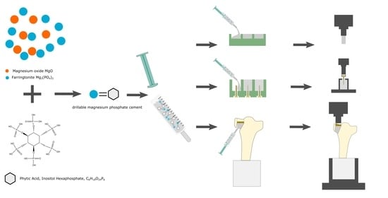
2.1. Cement Fabrication
2.2. Pretesting Series
2.3. X-ray Diffraction Analysis
2.4. Determination of pH Profile during Setting
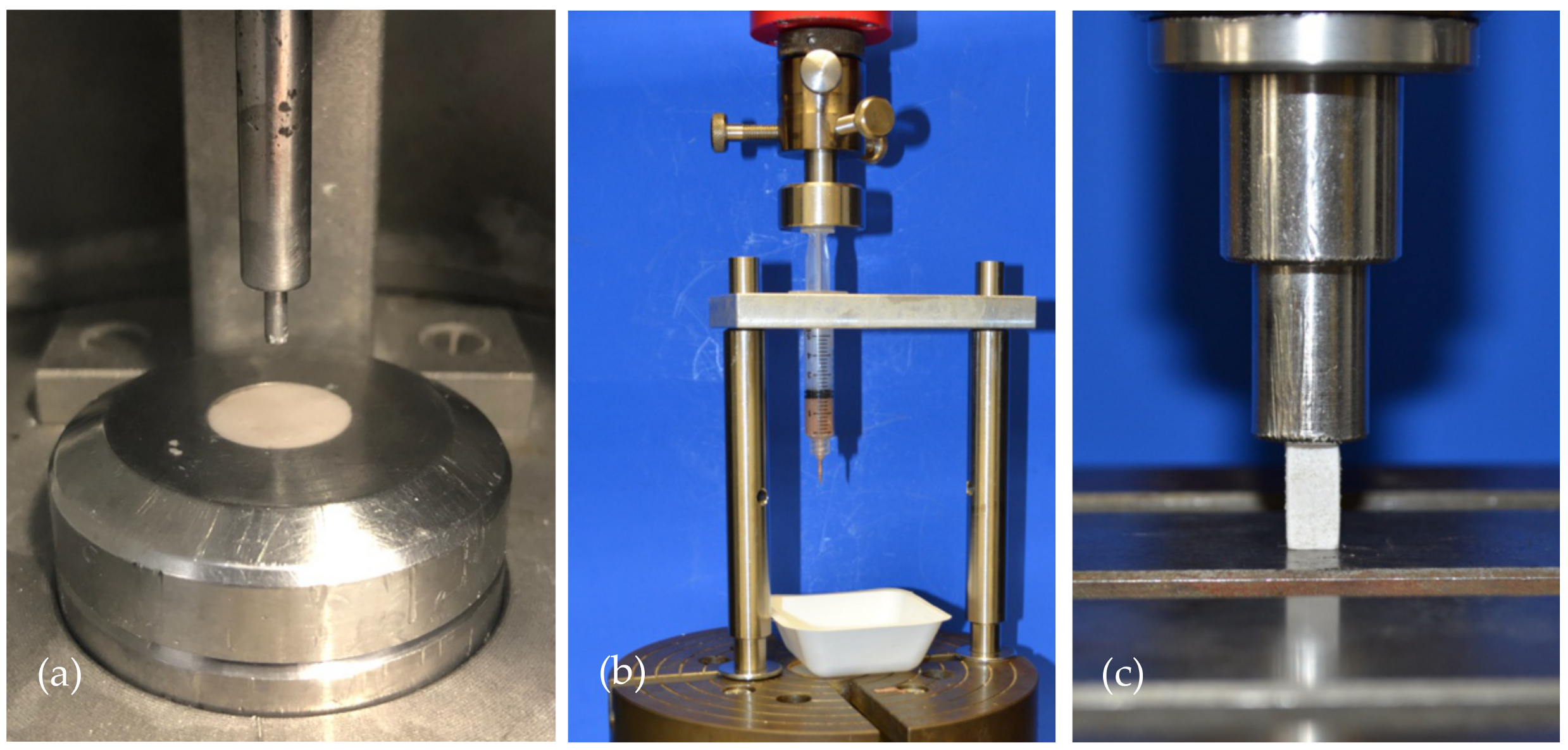
2.5. Gilmore Needle Test
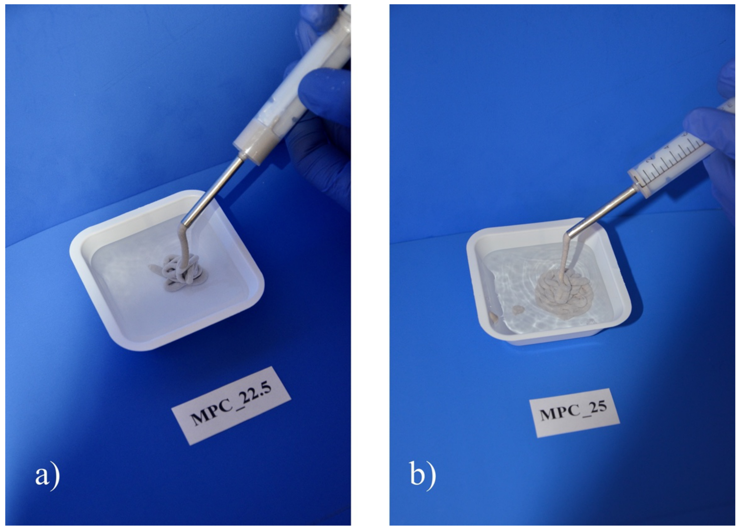
2.6. Injectability and Cohesion Testing
2.7. Compressive Strength Testing
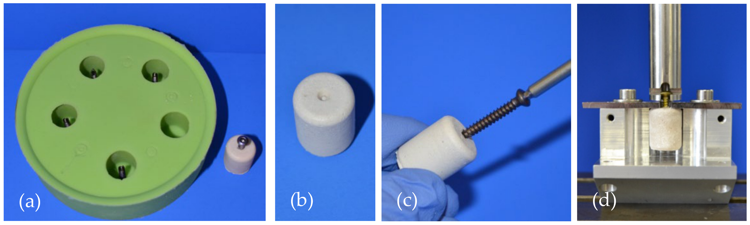
2.8. Screw Pullout Testing
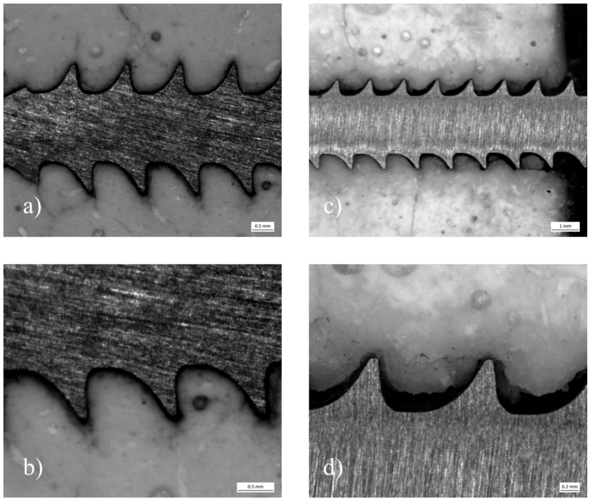
2.9. Analysis of the Microstructure at the Cement Screw Interface after Drilling
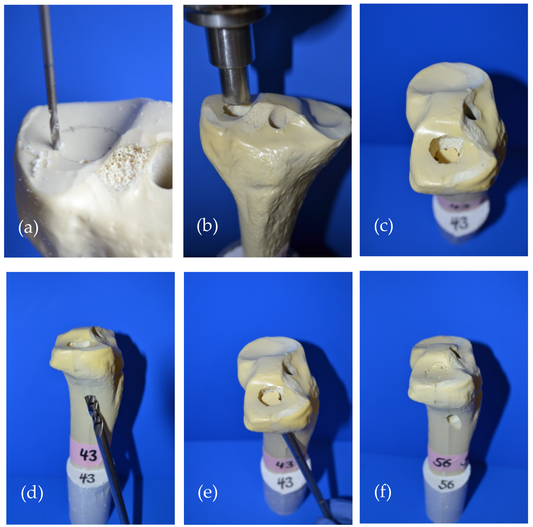
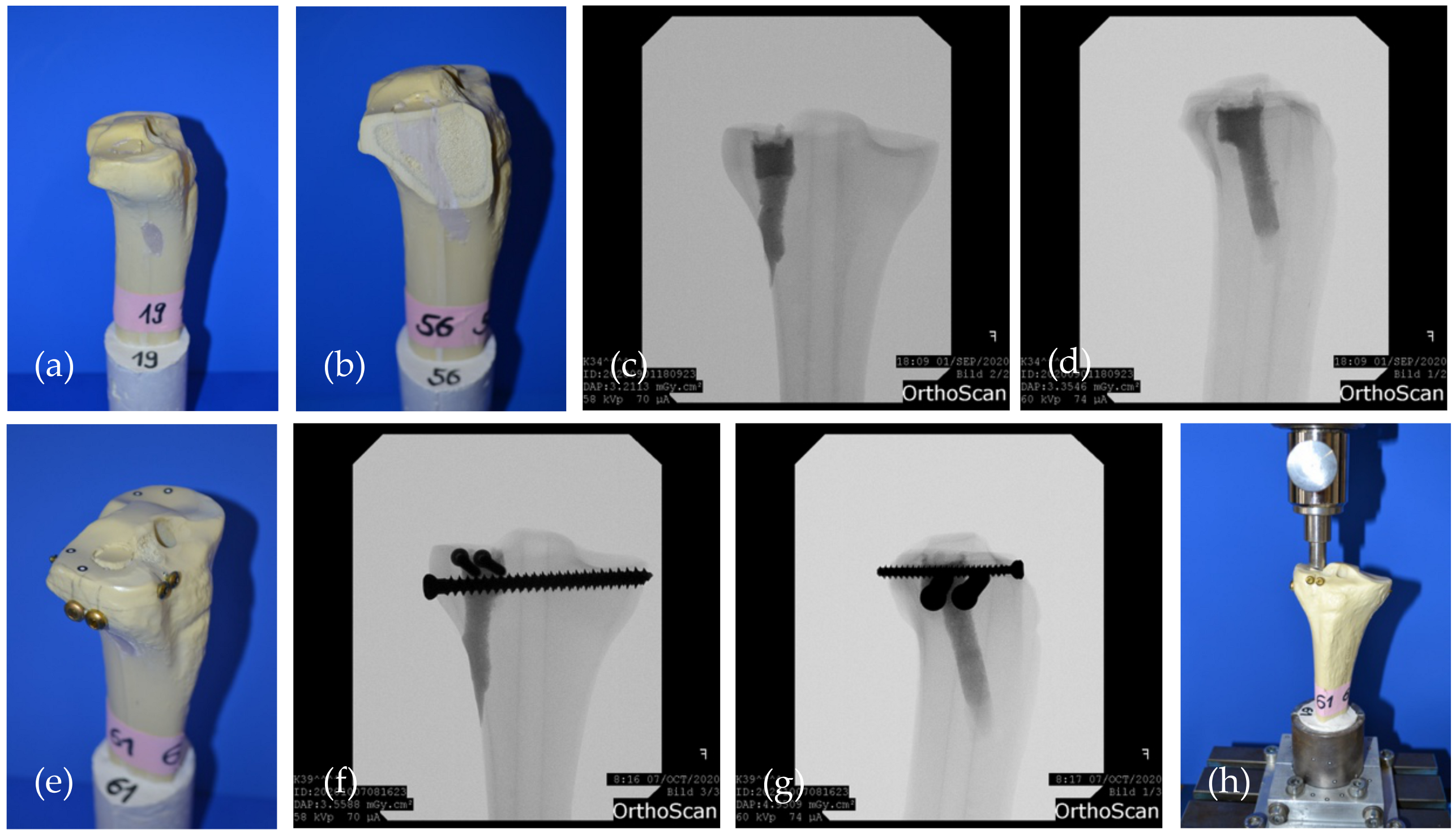
2.10. Testing in a Model for Tibial Head Fractures
2.11. Statistical Analysis
3. Results
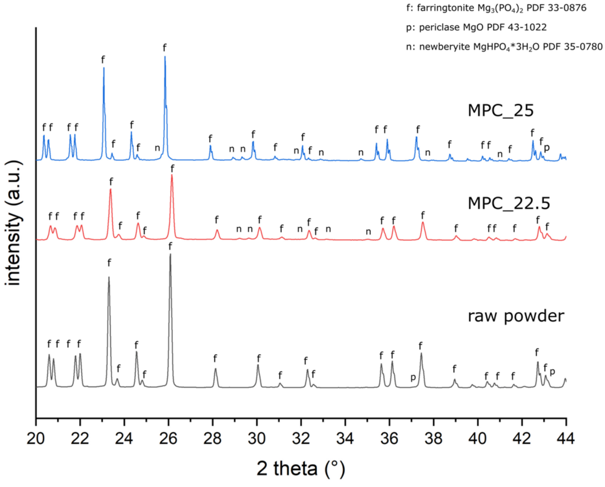
3.1. X-ray Diffraction Analysis
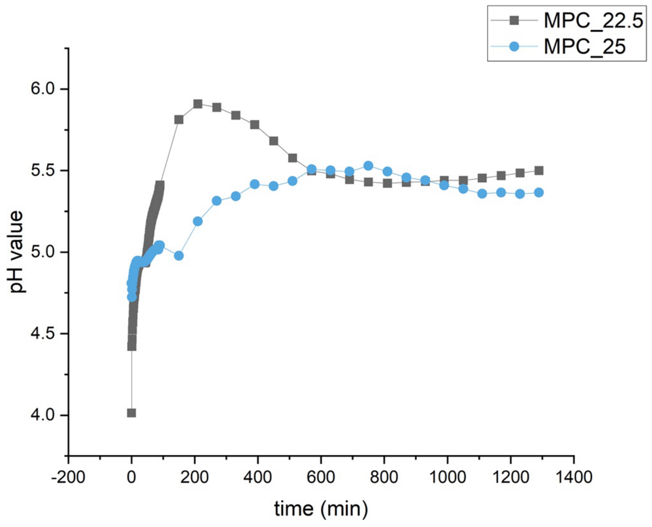
3.2. Determination of pH Profile during Setting
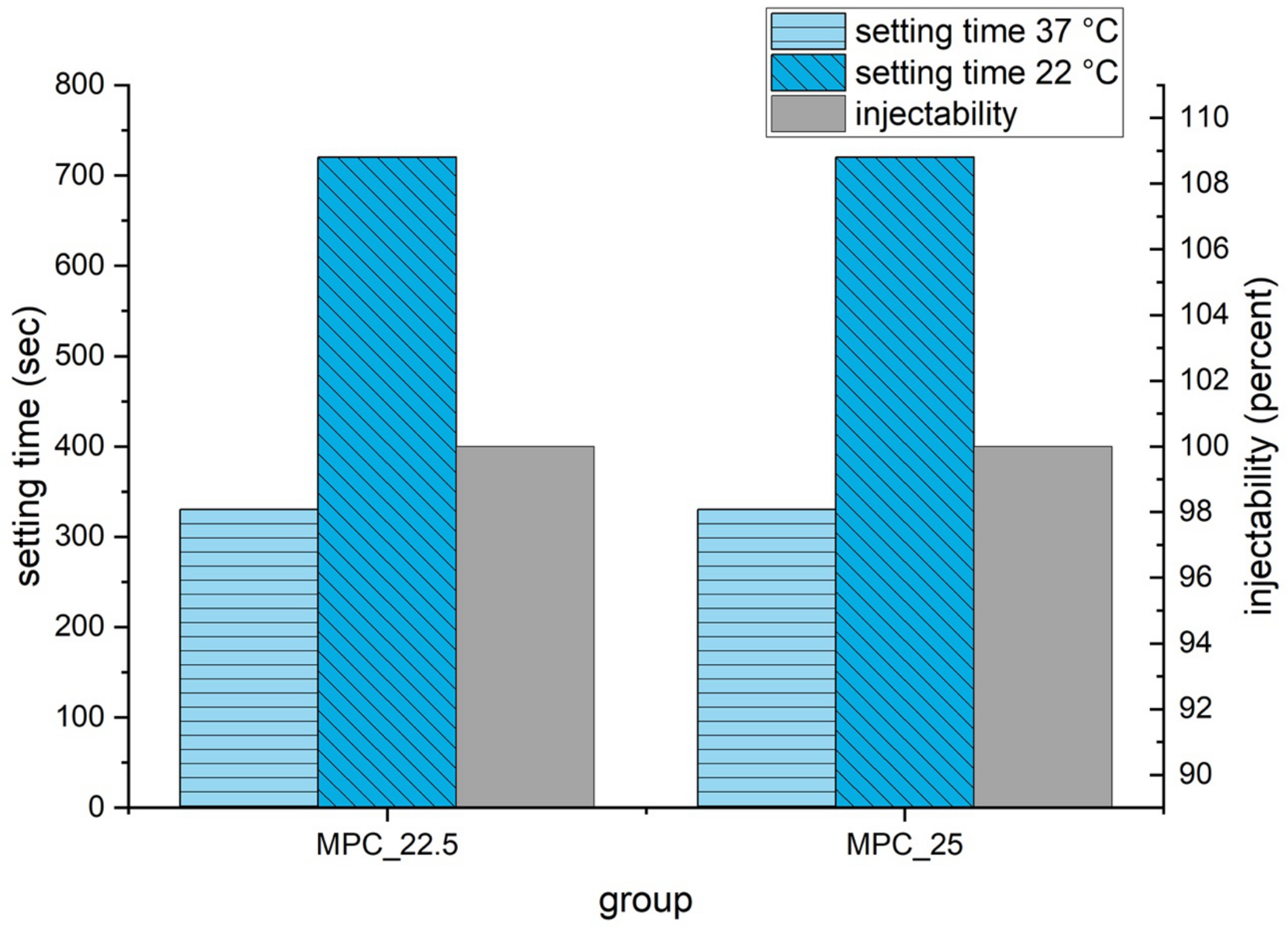
3.3. Setting Time, Injectability and Cohesion
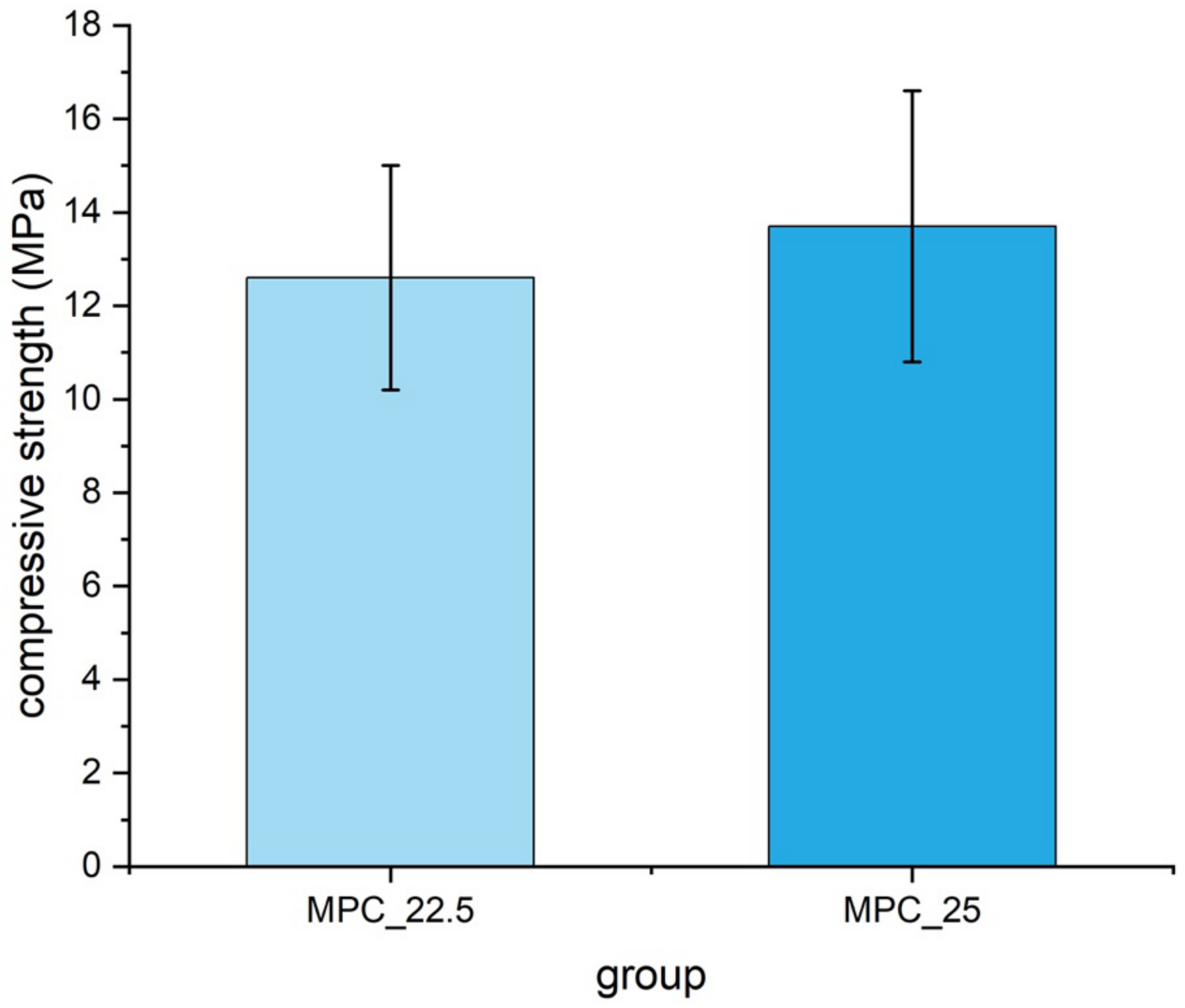
3.4. Compressive Strength
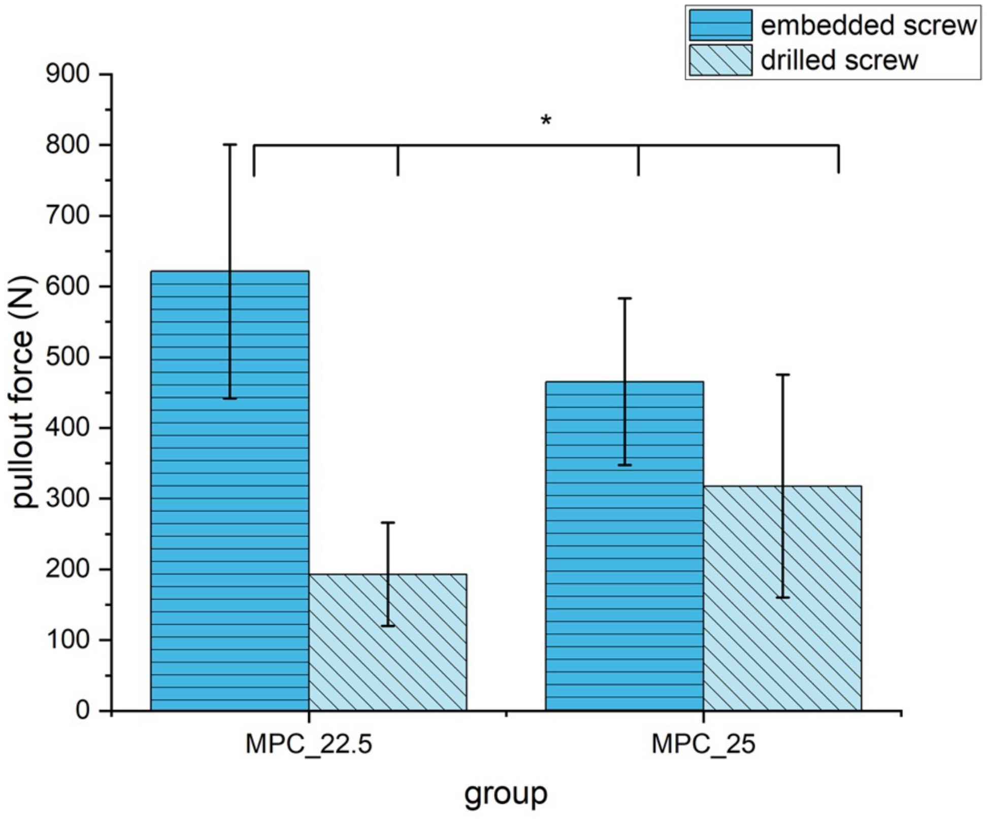
3.5. Screw Pullout Tests
3.6. Analysis of the Microstructure at the Cement Screw Interface after Drilling
3.7. Biomechanical Tests in a Clinically Relevant Fracture Model
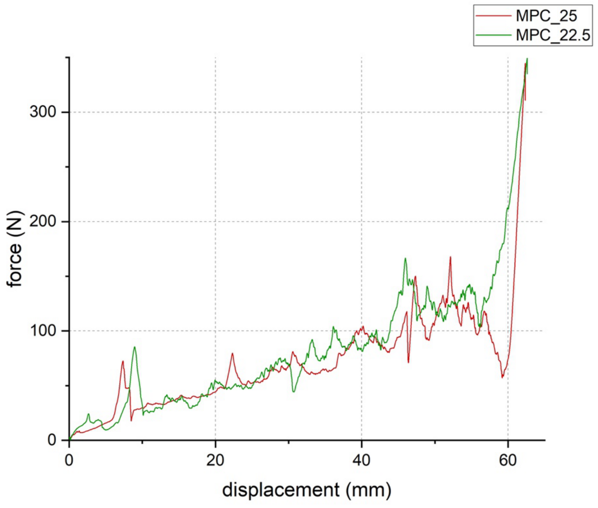
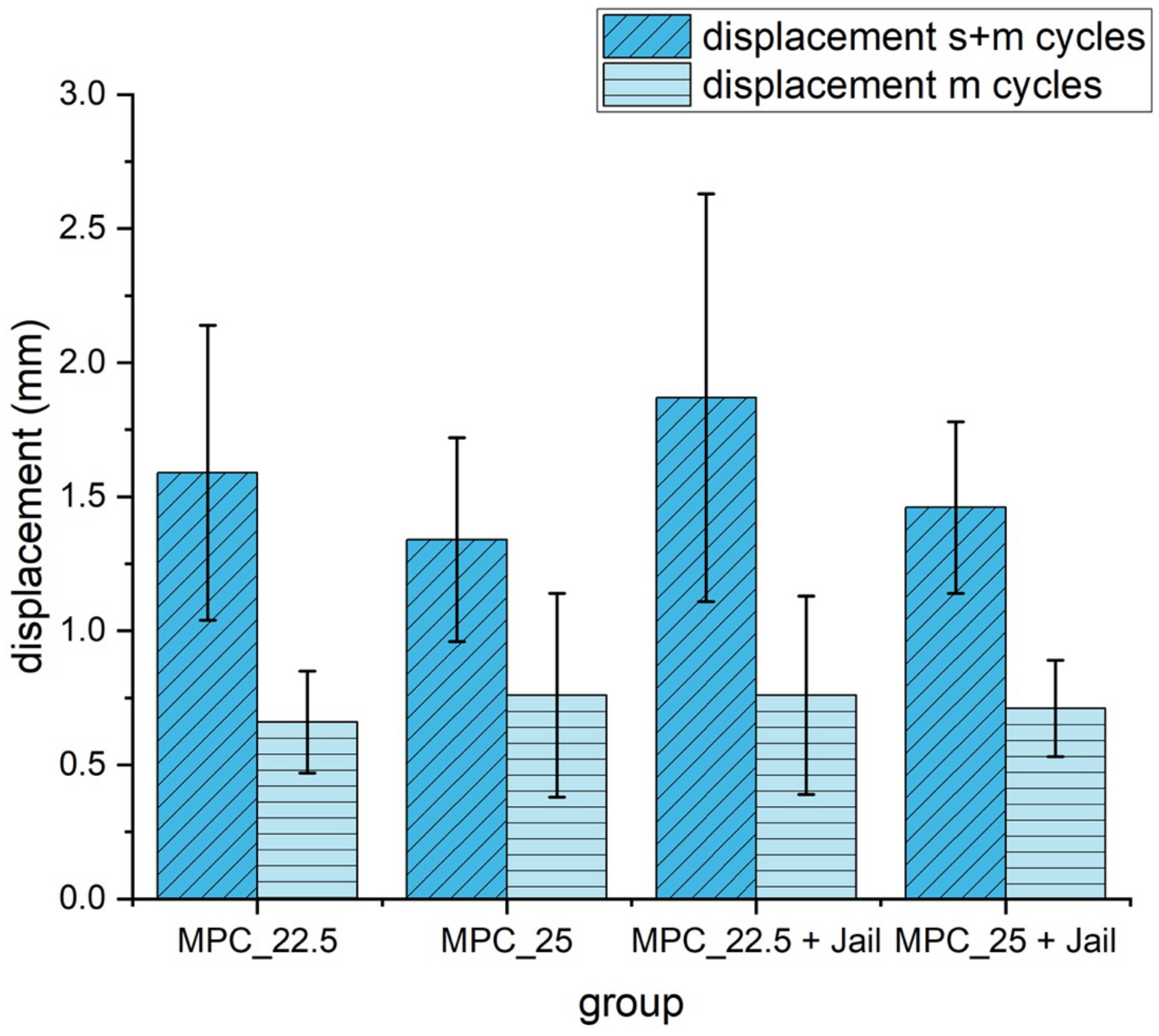
3.7.1. Displacement
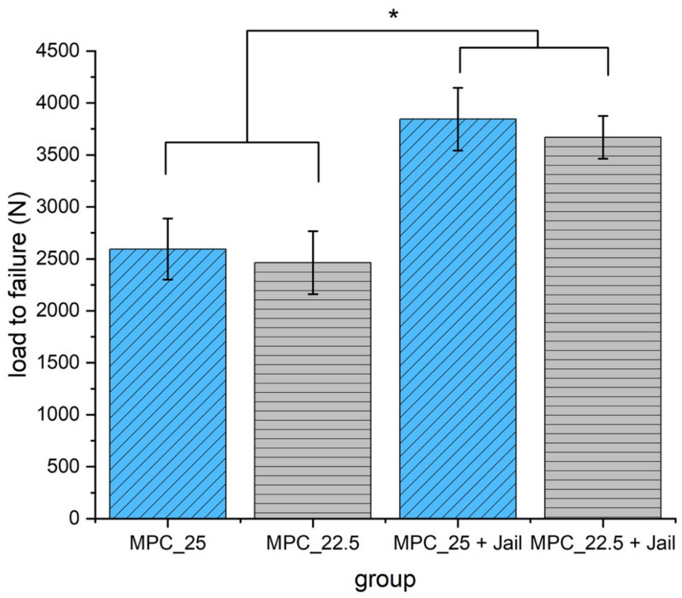
3.7.2. Maximum Load
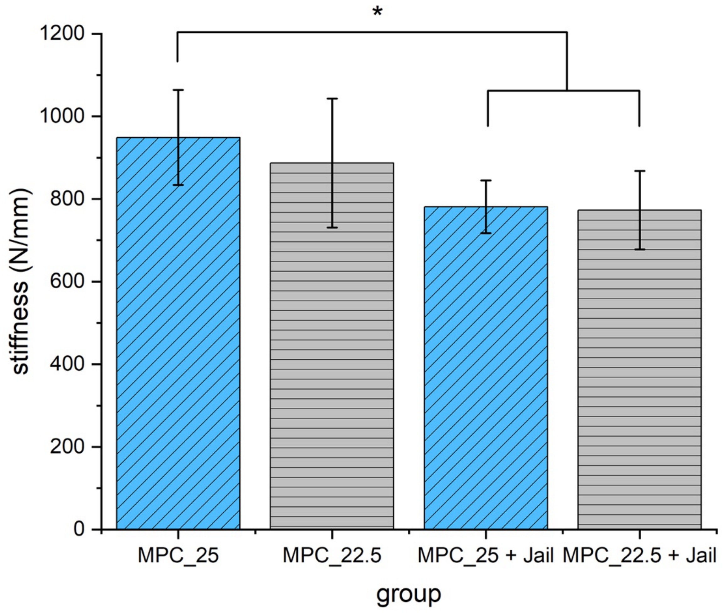
3.7.3. Stiffness
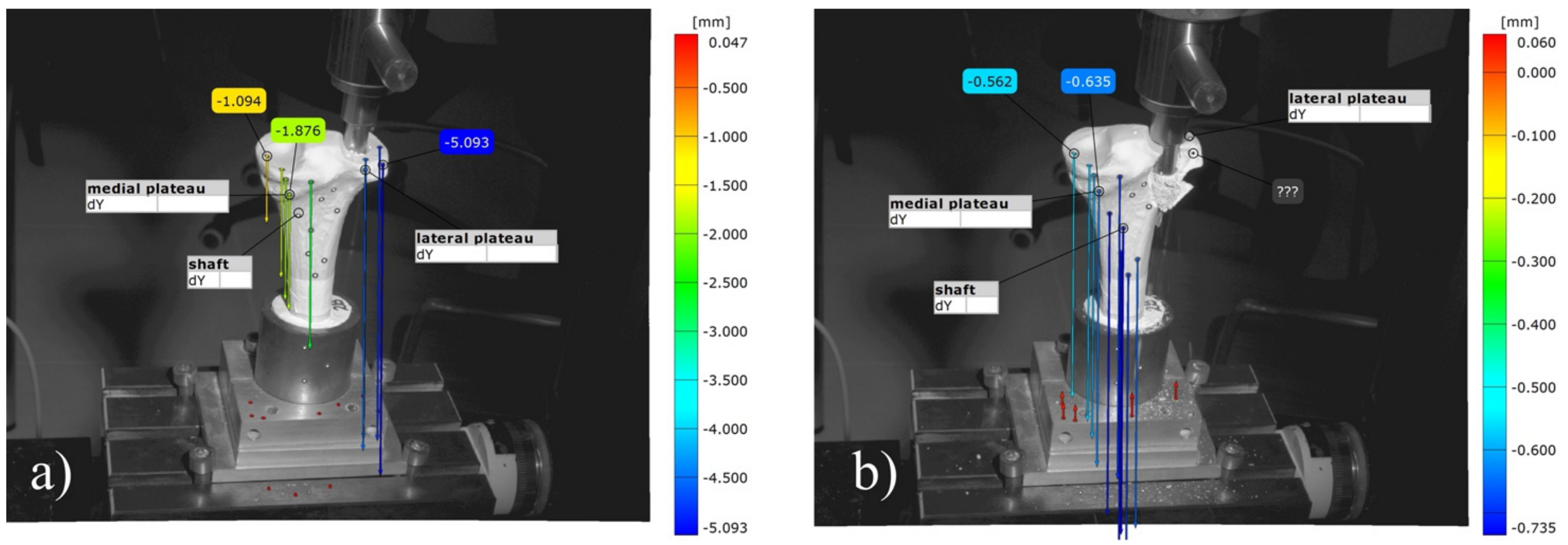
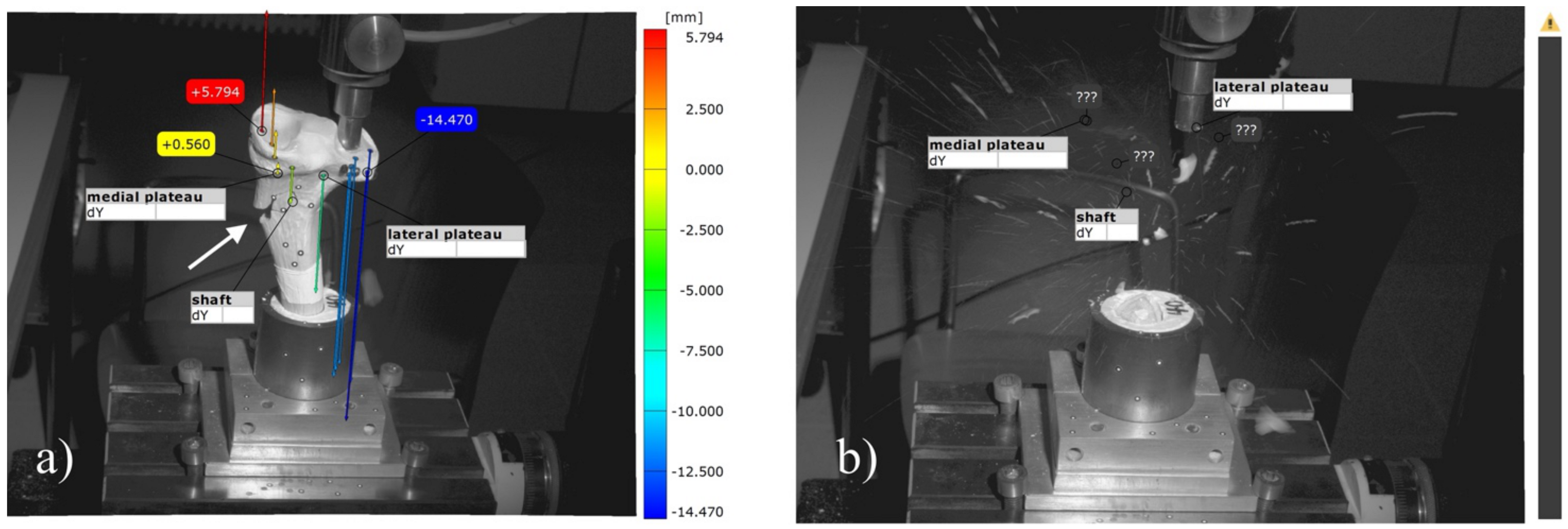
3.8. Analysis of the Optical 3D Metrology System
4. Discussion
5. Conclusions
Author Contributions
Funding
Institutional Review Board Statement
Informed Consent Statement
Data Availability Statement
Acknowledgments
Conflicts of Interest
References
- Marecek, G.; Centomo, H. Augmented fixation for fractures of the appendicular skeleton. J. Am. Acad. Orthop. Surg. 2019, 27, 823–833. [Google Scholar] [CrossRef] [PubMed]
- Hoelscher-Doht, S.; Jordan, M.C.; Bonhoff, C.; Frey, S.; Blunk, T.; Meffert, R.H. Bone substitute first or screws first? A biomechanical comparison of two operative techniques for tibial-head depression fractures. J. Orthop. Sci. 2014, 19, 978–983. [Google Scholar] [CrossRef] [PubMed]
- Brueckner, T.; Heilig, P.; Jordan, M.C.; Paul, M.M.; Blunk, T.; Meffert, R.H.; Gbureck, U.; Hoelscher-Doht, S. Biomechanical evaluation of promising different bone substitutes in a clinically relevant test set-up. Materials 2019, 12, 1364. [Google Scholar] [CrossRef]
- Bridgens, J.; Davies, S.; Tilley, L.; Norman, P.; Stockley, I. Orthopaedic bone cement: Do we know what we are using? J. Bone Joint Surg. Br. 2008, 90, 643–647. [Google Scholar] [CrossRef] [PubMed]
- Li, C.D.; Mason, J.; Yakimicki, D. Thermal characterization of PMMA-based bone cement curing. J. Mater. Sci. Mater. Med. 2004, 15, 85–89. [Google Scholar] [CrossRef] [PubMed]
- Dorozhkin, S.V. Calcium orthophosphate cements and concretes. Materials 2009, 2, 221–291. [Google Scholar] [CrossRef]
- Mestres, G.; Aguilera, F.S.; Manzanares, N.; Sauro, S.; Osorio, R.; Toledano, M.; Ginebra, M.P. Magnesium phosphate cements for endodontic applications with improved long-term sealing ability. Int. Endod. J. 2014, 47, 127–139. [Google Scholar] [CrossRef] [PubMed]
- Mestres, G.; Ginebra, M.P. Novel magnesium phosphate cements with high early strength and antibacterial properties. Acta Biomater. 2011, 7, 1853–1861. [Google Scholar] [CrossRef]
- Moseke, C.; Saratsis, V.; Gbureck, U. Injectability and mechanical properties of magnesium phosphate cements. J. Mater. Sci. Mater. Med. 2011, 22, 2591–2598. [Google Scholar] [CrossRef]
- Kanter, B.; Vikman, A.; Bruckner, T.; Schamel, M.; Gbureck, U.; Ignatius, A. Bone regeneration capacity of magnesium phosphate cements in a large animal model. Acta Biomater. 2018, 69, 352–361. [Google Scholar] [CrossRef]
- Grossardt, C.; Ewald, A.; Grover, L.M.; Barralet, J.E.; Gbureck, U. Passive and active in vitro resorption of calcium and magnesium phosphate cements by osteoclastic cells. Tissue Eng. Part A 2010, 16, 3687–3695. [Google Scholar] [CrossRef]
- Ewald, A.; Helmschrott, K.; Knebl, G.; Mehrban, N.; Grover, L.M.; Gbureck, U. Effect of cold-setting calcium- and magnesium phosphate matrices on protein expression in osteoblastic cells. J. Biomed. Mater. Res. B Appl. Biomater. 2011, 96, 326–332. [Google Scholar] [CrossRef]
- Bruckner, T.; Meininger, M.; Groll, J.; Kubler, A.C.; Gbureck, U. Magnesium phosphate cement as mineral bone adhesive. Materials 2019, 12, 3819. [Google Scholar] [CrossRef]
- Hurle, K.; Weichhold, J.; Brueckner, M.; Gbureck, U.; Brueckner, T.; Goetz-Neunhoeffer, F. Hydration mechanism of a calcium phosphate cement modified with phytic acid. Acta Biomater. 2018, 80, 378–389. [Google Scholar] [CrossRef]
- Doht, S.; Lehnert, T.; Frey, S.; Fehske, K.; Jansen, H.; Blunk, T.; Meffert, R.H. Effective combination of bone substitute and screws in the jail technique: A biomechanical study of tibial depression fractures. Int. Orthop. 2012, 36, 2121–2125. [Google Scholar] [CrossRef]
- ASTM C266-99. Standard Test Method for Time of Setting of Hydraulic-Cement Paste by Gillmore Needles; ASTM International: West Conshohocken, PA, USA, 1999. [Google Scholar] [CrossRef]
- Weimann, A.; Heinkele, T.; Herbort, M.; Schliemann, B.; Petersen, W.; Raschke, M.J. Minimally invasive reconstruction of lateral tibial plateau fractures using the jail technique: A biomechanical study. BMC Musculoskelet. Disord. 2013, 14, 120. [Google Scholar] [CrossRef]
- Jordan, M.C.; Zimmermann, C.; Gho, S.A.; Frey, S.P.; Blunk, T.; Meffert, R.H.; Hoelscher-Doht, S. Biomechanical analysis of different osteosyntheses and the combination with bone substitute in tibial head depression fractures. BMC Musculoskelet. Disord. 2016, 17, 287. [Google Scholar] [CrossRef]
- Lefkoe, T.P.; Trafton, P.G.; Ehrlich, M.G.; Walsh, W.R.; Dennehy, D.T.; Barrach, H.J.; Akelman, E. An experimental model of femoral condylar defect leading to osteoarthrosis. J. Orthop. Trauma 1993, 7, 458–467. [Google Scholar] [CrossRef]
- Cohen, Z.A.; McCarthy, D.M.; Kwak, S.D.; Legrand, P.; Fogarasi, F.; Ciaccio, E.J.; Ateshian, G.A. Knee cartilage topography, thickness, and contact areas from MRI: In-vitro calibration and in-vivo measurements. Osteoarthr. Cartil. 1999, 7, 95–109. [Google Scholar] [CrossRef]
- Shepherd, D.E.; Seedhom, B.B. Thickness of human articular cartilage in joints of the lower limb. Ann. Rheum. Dis. 1999, 58, 27–34. [Google Scholar] [CrossRef]
- Brown, T.D.; Anderson, D.D.; Nepola, J.V.; Singerman, R.J.; Pedersen, D.R.; Brand, R.A. Contact stress aberrations following imprecise reduction of simple tibial plateau fractures. J. Orthop. Res. 1988, 6, 851–862. [Google Scholar] [CrossRef]
- Honkonen, S.E. Indications for surgical treatment of tibial condyle fractures. Clin. Orthop. Relat. Res. 1994, 302, 199–205. [Google Scholar] [CrossRef]
- McDonald, E.; Chu, T.; Tufaga, M.; Marmor, M.; Singh, R.; Yetkinler, D.; Matityahu, A.; Buckley, J.M.; McClellan, R.T. Tibial plateau fracture repairs augmented with calcium phosphate cement have higher in situ fatigue strength than those with autograft. J. Orthop. Trauma 2011, 25, 90–95. [Google Scholar] [CrossRef]
- Meininger, S.; Blum, C.; Schamel, M.; Barralet, J.E.; Ignatius, A.; Gbureck, U. Phytic acid as alternative setting retarder enhanced biological performance of dicalcium phosphate cement in vitro. Sci. Rep. 2017, 7, 558. [Google Scholar] [CrossRef]
- Kanter, B.; Geffers, M.; Ignatius, A.; Gbureck, U. Control of in vivo mineral bone cement degradation. Acta Biomater. 2014, 10, 3279–3287. [Google Scholar] [CrossRef]
- Apelt, D.; Theiss, F.; El-Warrak, A.O.; Zlinszky, K.; Bettschart-Wolfisberger, R.; Bohner, M.; Matter, S.; Auer, J.A.; von Rechenberg, B. In vivo behavior of three different injectable hydraulic calcium phosphate cements. Biomaterials 2004, 25, 1439–1451. [Google Scholar] [CrossRef]
- Jamshidi, P.; Bridson, R.H.; Wright, A.J.; Grover, L.M. Brushite cement additives inhibit attachment to cell culture beads. Biotechnol. Bioeng. 2013, 110, 1487–1494. [Google Scholar] [CrossRef]


| wt% IP 6 | wt% MgO | wt% Mg3(PO4)2 | PLR g/mL | Amount Ratio | Comment | |
|---|---|---|---|---|---|---|
| Cement 1 | 20.0 | 6.0 | 94.0 | 2 | 9.85 | setting time too fast |
| Cement 2 | 22.5 | 6.8 | 93.2 | 2 | 9.92 | setting time too fast |
| Cement 3 | 25.0 | 7.5 | 92.5 | 2 | 9.85 | setting time too fast |
| Cement 4/MPC_25 | 25.0 | 7.5 | 92.5 | 1.71 | 8.44 | handling and drilling appropriate |
| Cement 5/MPC_22.5 | 22.5 | 6.8 | 93.2 | 1.71 | 8.50 | handling and drilling appropriate |
| Cement 6 | 22.5 | 6.8 | 93.2 | 1.82 | 9.02 | drilling impossible |
| Cement 7 | 20.0 | 6.8 | 93.2 | 1.71 | 9.56 | drilling impossible |
| Cement 8 | 22.5 | 4.73 | 95.27 | 1.71 | 5.91 | setting time too slow, too liquid |
| Cement 9 | 22.5 | 7.2 | 92.80 | 1.71 | 9.00 | drilling impossible |
| Cement 10 | 22.5 | 7.5 | 92.5 | 1.71 | 9.38 | drilling impossible |
| Cement 11 | 22.5 | 7.87 | 92.13 | 1.71 | 9.84 | drilling impossible |
| Cement 12 | 25.0 | 8.05 | 91.95 | 1.71 | 9.06 | drilling impossible |
| Cement 13 | 25.0 | 8.78 | 91.22 | 1.71 | 9.88 | drilling impossible |
| Test Groups | MPC_22.5 | MPC_25 |
|---|---|---|
| compressive strength | n = 10 | n = 10 |
| screw pullout tests | - | - |
| embedded | n = 10 | n = 10 |
| manually drilled | n = 10 | n = 10 |
| fracture model | - | - |
| bone cement only | n = 9 | n = 9 |
| bone cement + jail-technique | n = 9 | n = 9 |
| Quantitative XRD | Farringtonite (Mg3(PO4)2) | Periclase (MgO) | Newberyite (MgHPO4 × 3H2O) |
|---|---|---|---|
| raw powder | 98.5% | 1.5% | |
| MPC_22.5 | 90.8% | 3.9% | 5.3% |
| MPC_25 | 90.5% | 2.5% | 7% |
Publisher’s Note: MDPI stays neutral with regard to jurisdictional claims in published maps and institutional affiliations. |
© 2021 by the authors. Licensee MDPI, Basel, Switzerland. This article is an open access article distributed under the terms and conditions of the Creative Commons Attribution (CC BY) license (https://creativecommons.org/licenses/by/4.0/).
Share and Cite
Heilig, P.; Sandner, P.; Jordan, M.C.; Jakubietz, R.G.; Meffert, R.H.; Gbureck, U.; Hoelscher-Doht, S. Experimental Drillable Magnesium Phosphate Cement Is a Promising Alternative to Conventional Bone Cements. Materials 2021, 14, 1925. https://doi.org/10.3390/ma14081925
Heilig P, Sandner P, Jordan MC, Jakubietz RG, Meffert RH, Gbureck U, Hoelscher-Doht S. Experimental Drillable Magnesium Phosphate Cement Is a Promising Alternative to Conventional Bone Cements. Materials. 2021; 14(8):1925. https://doi.org/10.3390/ma14081925
Chicago/Turabian StyleHeilig, Philipp, Phoebe Sandner, Martin Cornelius Jordan, Rafael Gregor Jakubietz, Rainer Heribert Meffert, Uwe Gbureck, and Stefanie Hoelscher-Doht. 2021. "Experimental Drillable Magnesium Phosphate Cement Is a Promising Alternative to Conventional Bone Cements" Materials 14, no. 8: 1925. https://doi.org/10.3390/ma14081925
APA StyleHeilig, P., Sandner, P., Jordan, M. C., Jakubietz, R. G., Meffert, R. H., Gbureck, U., & Hoelscher-Doht, S. (2021). Experimental Drillable Magnesium Phosphate Cement Is a Promising Alternative to Conventional Bone Cements. Materials, 14(8), 1925. https://doi.org/10.3390/ma14081925