
Surface Quality Improvement by Using a Novel Driving System Design in Single-Side Planetary Abrasive Lapping


Abstract
:1. Introduction
2. Evaluation of Surface Quality with the Novel Driving System
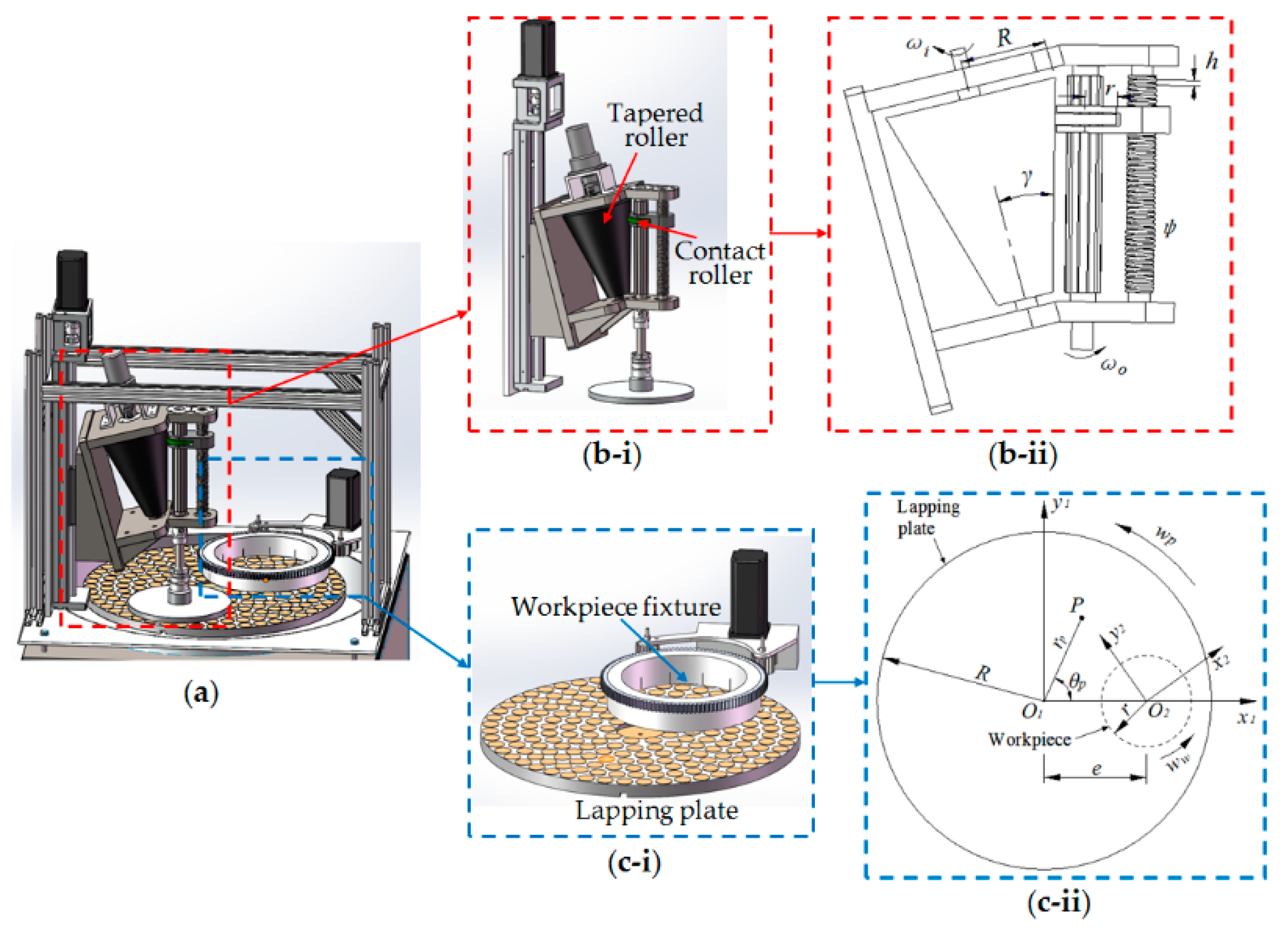
2.1. Mechanism of the Novel Driving System to Realize the Irrational Rotation Speed Ratio
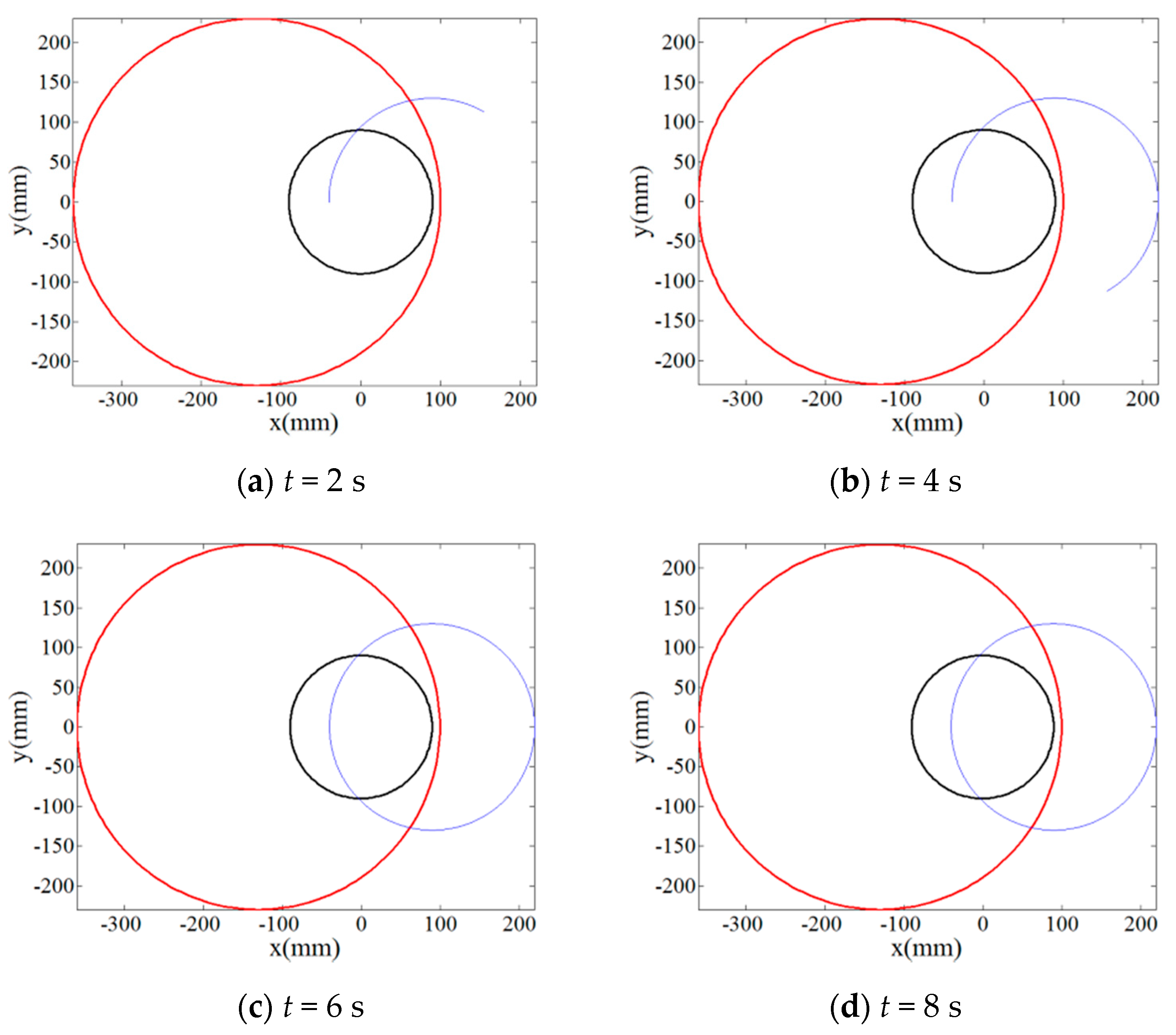
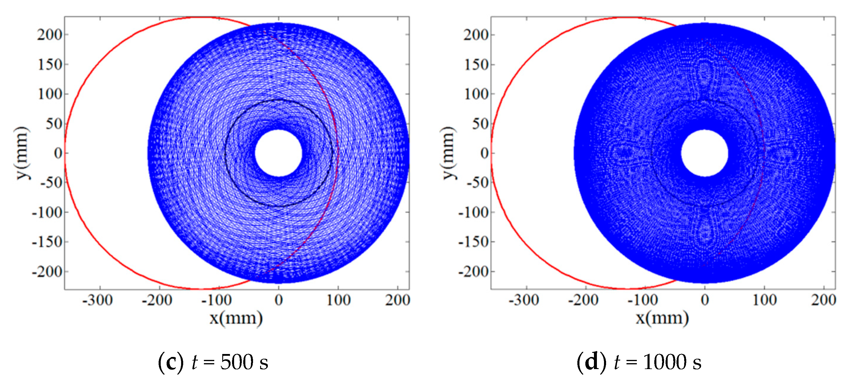
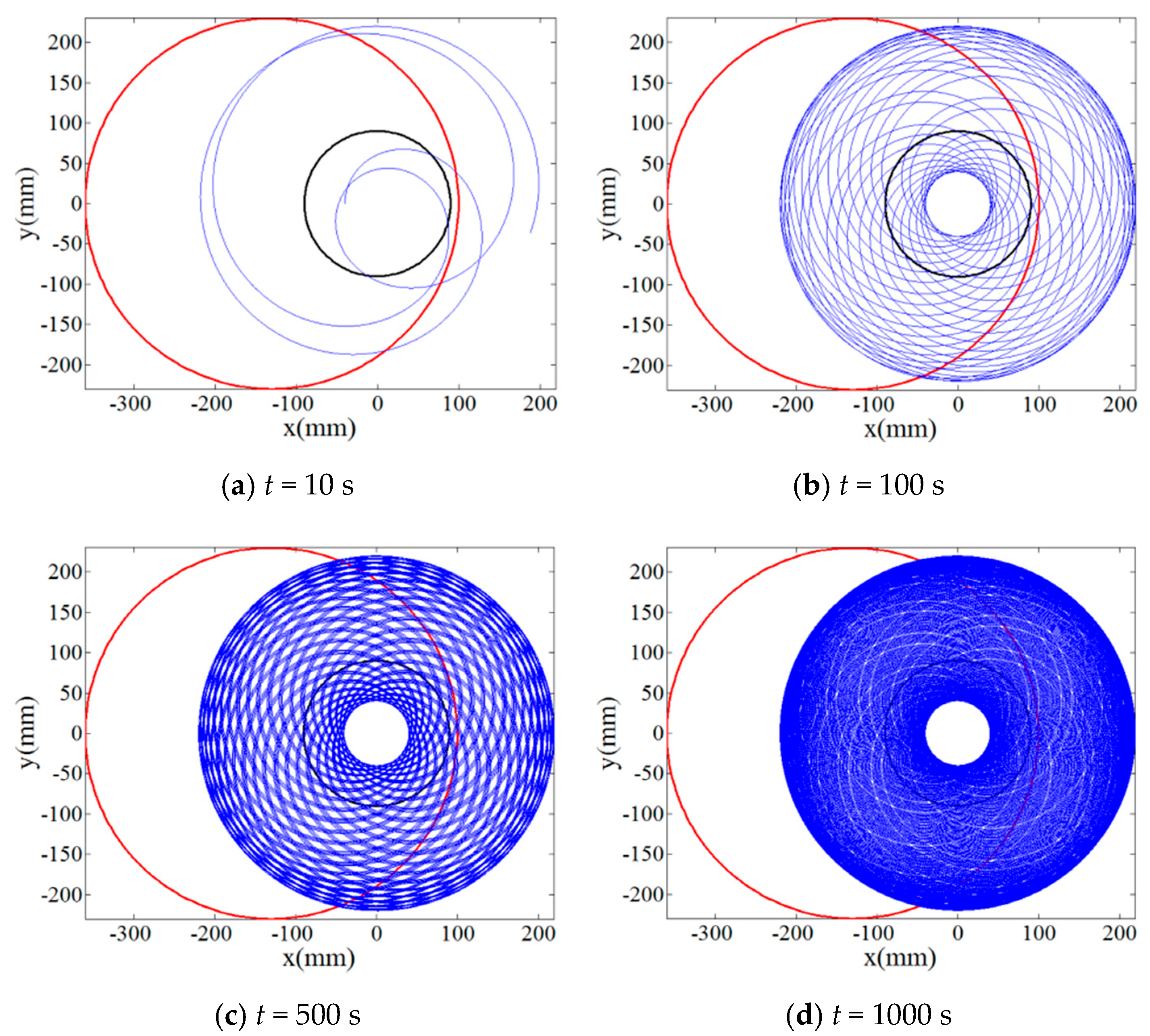
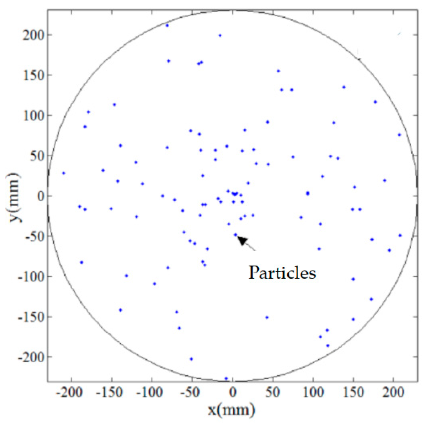
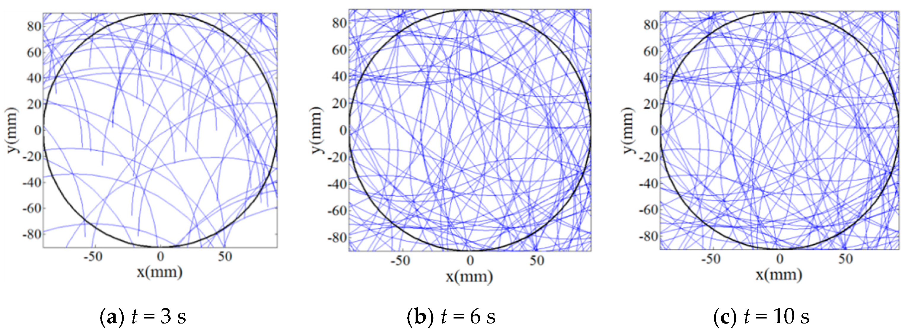
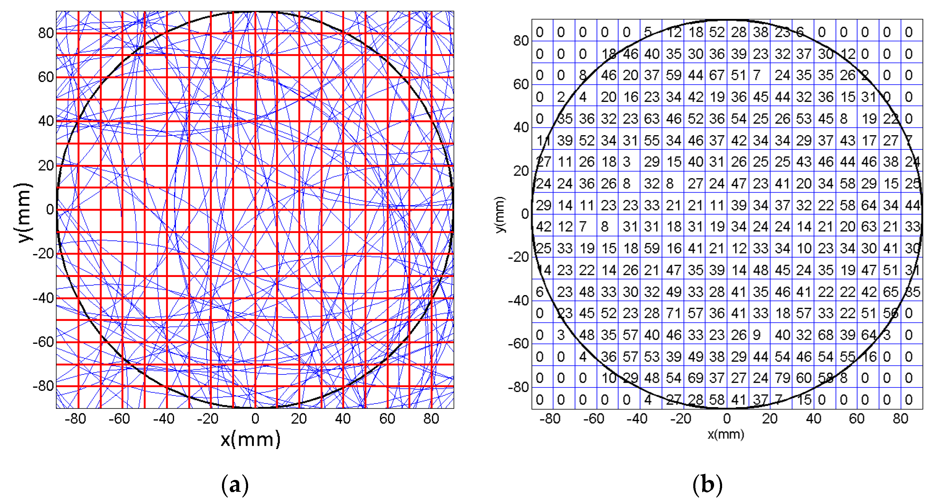
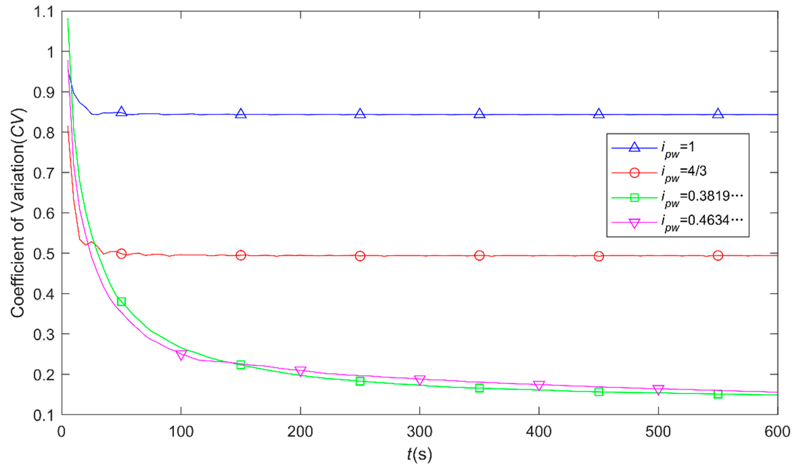
2.2. Uniformity Assessment of Particle Trajectories Moving on the Surface of Workpiece by Using the Novel Driving System
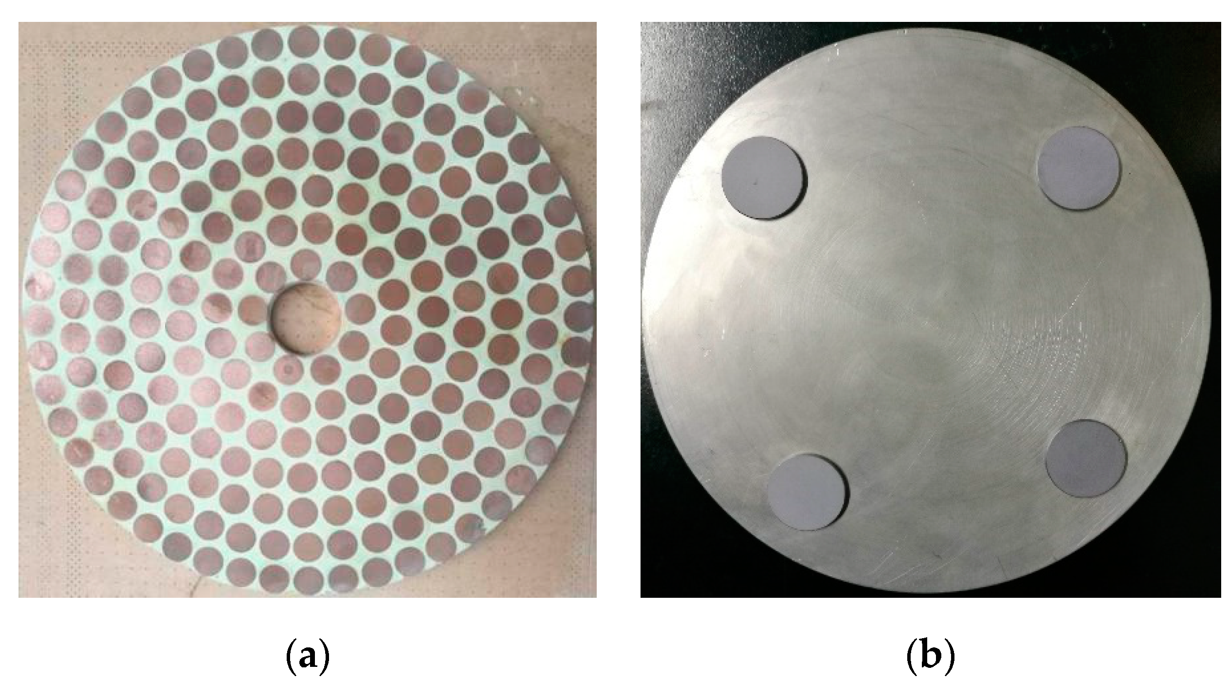
3. Performance Testing of the Novel Driving System
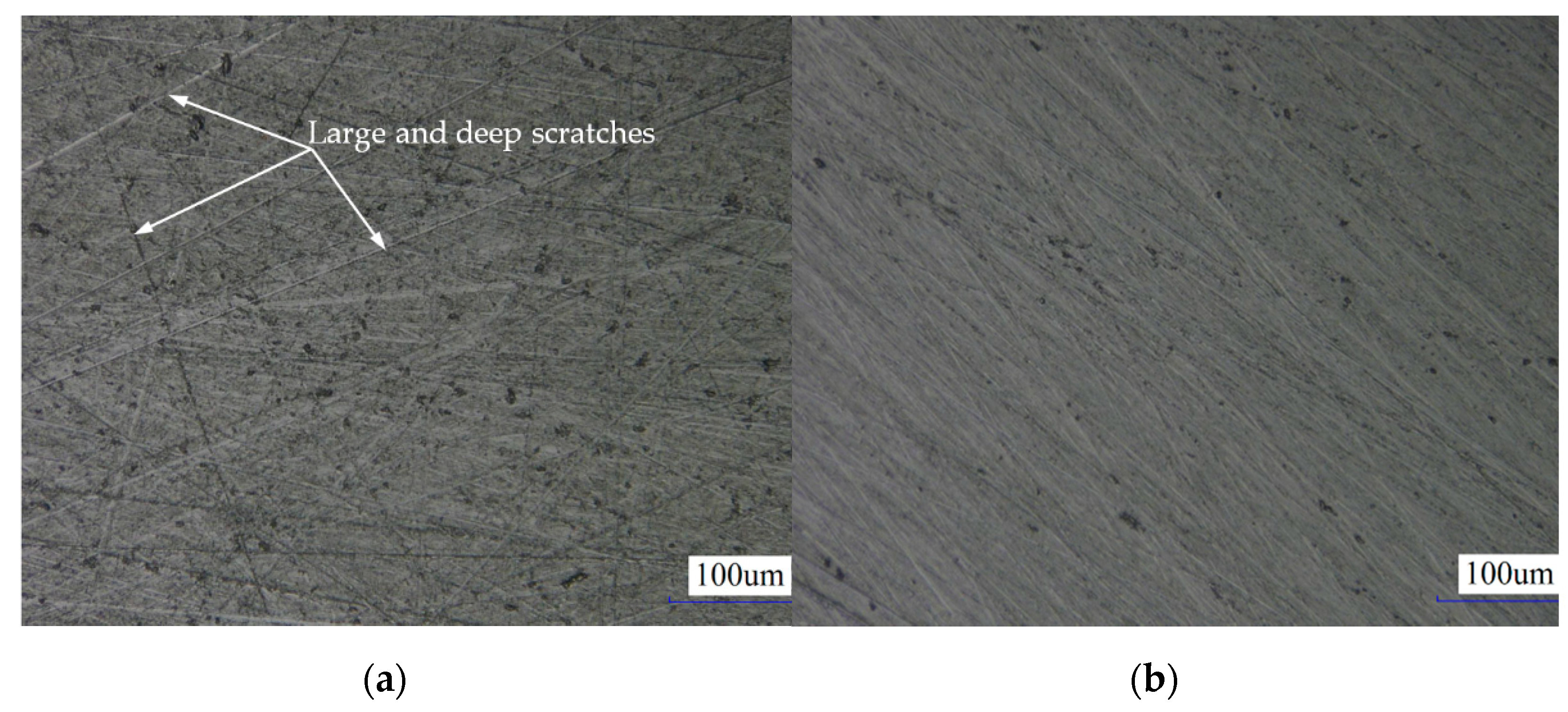
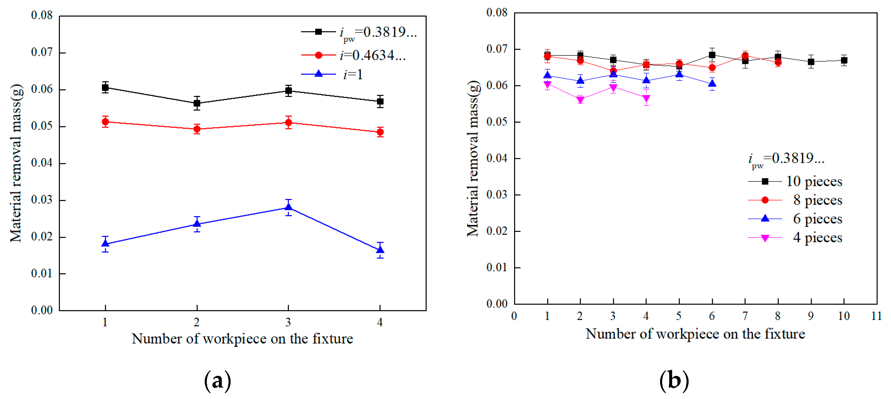
4. Results and Discussion
5. Conclusions
Author Contributions
Funding
Data Availability Statement
Acknowledgments
Conflicts of Interest
References
- Dražumerič, R.; Badger, J.; RoininenP, R.; Krajnikc, P. On geometry and kinematics of abrasive processes: The theory of aggressiveness. Int. J. Mach. Tools Manuf. 2020, 154, 103567. [Google Scholar] [CrossRef]
- Chen, Z.Z.; Qi, H.; Zhao, B.; Zhou, Y.; Shi, L.W.; Li, H.N.; Ding, W.F. On the tribology and grinding performance of graphene-modified porous composite-bonded CBN wheel. Ceram. Int. 2021, 47, 3259–3266. [Google Scholar] [CrossRef]
- Zhao, J.; Huang, J.F.; Xiang, Y.C.; Wang, R.; Xu, X.Q.; Ji, S.M.; Hang, W. Effect of a protective coating on the surface integrity of a microchannel produced by microultrasonic machining. J. Manuf. Process. 2021, 61, 280–295. [Google Scholar] [CrossRef]
- Qi, H.; Qin, S.K.; Cheng, Z.C.; Teng, Q.; Hong, T.; Xie, Y. Towards understanding performance enhancing mechanism of micro-holes on K9 glasses using ultrasonic vibration-assisted abrasive slurry jet. J. Manuf Process. 2021, 64, 585–593. [Google Scholar] [CrossRef]
- Luna, G.G.; Axinte, D.; Novovic, D. Influence of grit geometry and fibre orientation on the abrasive material removal mechanisms of SiC/SiC Ceramic Matrix Composites (CMCs). Int. J. Mach. Tools Manuf. 2020, 157, 103580. [Google Scholar] [CrossRef]
- Qi, H.; Qin, S.K.; Cheng, Z.C.; Zou, Y.L.; Cai, D.H.; Wen, D.H. DEM and experimental study on the ultrasonic vibration-assisted abrasive finishing of WC-8Co cemented carbide cutting edge. Powder Technol. 2021, 378, 716–723. [Google Scholar] [CrossRef]
- Ge, J.Q.; Li, C.; Gao, Z.Y.; Ren, Y.L.; Xu, X.S.; Li, C.; Xie, Y. Softness abrasive flow polishing method using constrained boundary vibration. Powder Technol. 2021, 382, 173–187. [Google Scholar] [CrossRef]
- Tamura, S.; Matsumura, T. Delamination-free drilling of carbon fiber reinforced plastic with variable feed rate. Precis. Eng. 2021, 70, 70–76. [Google Scholar] [CrossRef]
- Wang, Y.S.; Zou, B.; Huang, C.Z. Tool wear mechanisms and micro-channels quality in micro-machining of Ti-6Al-4V alloy using the Ti(C7N3)-based cermet micro-mills. Tribol. Int. 2019, 134, 60–76. [Google Scholar] [CrossRef]
- Xing, H.Y.; Zou, B.; Liu, X.Y.; Wang, X.F.; Chen, Q.H.; Fu, X.S.; Li, Y.S. Effect of particle size distribution on the preparation of ZTA ceramic paste applying for stereolithography 3D printing. Powder Technol. 2020, 359, 314–322. [Google Scholar] [CrossRef]
- Cheng, Z.P.; Gao, H.; Liu, Z.Y.; Guo, D.M. Investigation of the trajectory uniformity in water dissolution ultraprecision continuous polishing of large-sized KDP crystal. Int. J. Extrem. Manuf. 2020, 2, 045101. [Google Scholar] [CrossRef]
- Suzuki, N.; Misono, H.; Shamoto, E.; Hashimoto, Y.; Yasuda, H.; Mochizuki, Y. Material removal efficiency improvement by orientation control of CMP pad surface asperities. Precis. Eng. 2020, 62, 83–88. [Google Scholar] [CrossRef]
- Rafal, R.; Michal, W.; Grzegorz, K. Material ratio curve as information on the state of surface topography—A review. Precis. Eng. 2020, 65, 240–258. [Google Scholar] [CrossRef]
- Li, H.N.; Yang, Y.; Zhao, Y.J.; Zhang, Z.L.; Zhu, W.Q.; Wang, W.L.; Qi, H. On the periodicity of fixed-abrasive planetary lapping based on a generic model. J. Manuf. Process. 2019, 44, 271–287. [Google Scholar] [CrossRef]
- Yuan, J.L.; Yao, W.F.; Zhao, P.; Lyu, B.H.; Chen, Z.X.; Zhong, M.P. Kinematics and trajectory of both-sides cylindrical lapping process in planetary motion type. Int. J. Mach. Tools Manuf. 2015, 92, 60–71. [Google Scholar] [CrossRef]
- Wen, D.H.; Qi, H.; Ma, L.; Lu, C.D.; Li, G. Kinematics and trajectory analysis of the fixed abrasive lapping process in machining of interdigitated micro-channels on bipolar plates. Precis. Eng. 2016, 44, 192–202. [Google Scholar] [CrossRef]
- Zhang, L.; Ji, R.Q.; Fu, Y.F.; Qi, H.; Kong, F.Z.; Li, H.N.; Tangwarodomnukun, V. Investigation on particle motions and resultant impact erosion on quartz crystals by the micro-particle laden waterjet and airjet. Powder Technol. 2020, 360, 452–461. [Google Scholar] [CrossRef]
- Li, L.; Qi, H.; Yin, Z.C.; Li, D.F.; Zhu, Z.L.; Tangwarodomnukun, V.; Tan, D.P. Investigation on the multiphase sink vortex Ekman pumping effects by CFD-DEM coupling method. Powder Technol. 2020, 360, 462–480. [Google Scholar] [CrossRef]
- Tso, P.L.; Wang, Y.Y.; Tsai, M.J. A study of carrier motion on a dual-face CMP machine. J. Mater. Process. Tech. 2001, 116, 194–200. [Google Scholar] [CrossRef]
- Zhang, Z.; Ni, X.Q.; Wu, H.L.; Sun, M.; Bao, G.J.; Wu, H.P.; Jiang, S.F. Pneumatically actuated soft gripper with bistable structures. Soft Robot. 2021. [Google Scholar] [CrossRef]
- Zhao, J.; Wang, R.; Jiang, E.Y.; Ji, S.M. Research on a new method for optimizing surface roughness of cavitation abrasive flow polishing monocrystalline silicon. Int. J. Adv. Manuf. Technol. 2021, 1–13. [Google Scholar] [CrossRef]
- Zhao, J.; Jiang, E.Y.; Qi, H.; Ji, S.M.; Chen, Z.Z. A novel polishing method for single-crystal silicon using the cavitation rotary abrasive flow. Precis. Eng. 2020, 61, 72–81. [Google Scholar] [CrossRef]
- Wu, Q.; Zhang, L.C. Microstructure-based three-dimensional characterization of chip formation and surface generation in the machining of particulate-reinforced metal matrix composites. Int. J. Extrem. Manuf. 2020, 2, 045103. [Google Scholar] [CrossRef]
- Chen, N.; Li, H.N.; Wu, J.M.; Li, Z.J.; Li, L.; Liu, G.Y.; He, N. Advances in micro milling: From tool fabrication to process outcomes. Int. J. Mach. Tools Manuf. 2021, 160, 103670. [Google Scholar] [CrossRef]
- Zhu, H.; Zhang, Z.; Zhou, J.; Xu, K.; Zhao, D.; Tangwarodomnukun, V. A computational study of heat transfer and material removal in picosecond laser micro-grooving of copper. Opt. Laser Technol. 2021, 137, 106792. [Google Scholar] [CrossRef]


| φ (rad) | ipw | Approximate Value of ipw |
|---|---|---|
| 16π | 0.3819… | |
| 80π | 0.4634… |
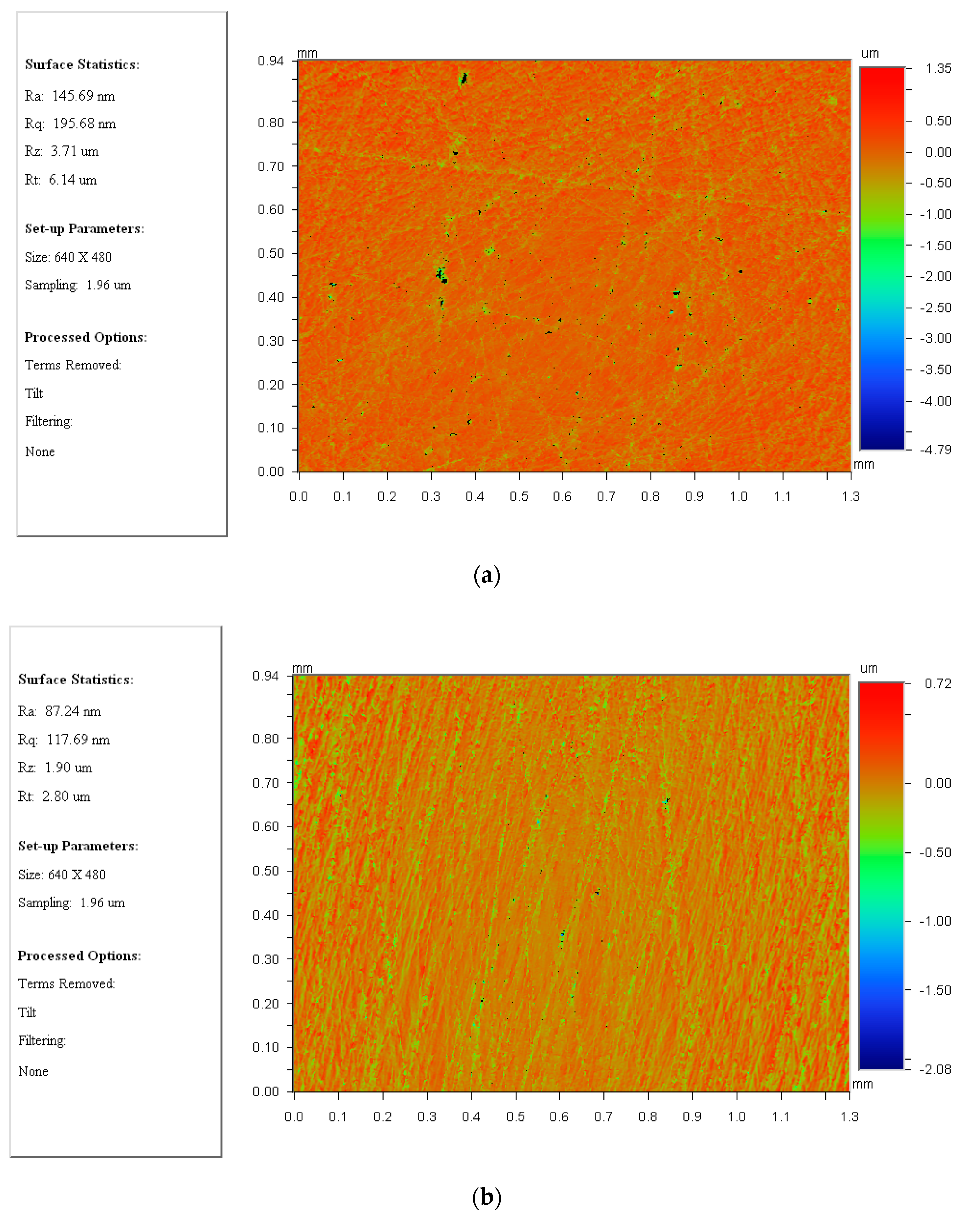
| ipw | Ra (nm) | Rq (nm) | Rz (µm) | Rt (µm) |
|---|---|---|---|---|
| 1 | 145.69 | 195.68 | 3.71 | 6.14 |
| 0.3819… | 87.24 | 117.69 | 1.9 | 2.8 |
Publisher’s Note: MDPI stays neutral with regard to jurisdictional claims in published maps and institutional affiliations. |
© 2021 by the authors. Licensee MDPI, Basel, Switzerland. This article is an open access article distributed under the terms and conditions of the Creative Commons Attribution (CC BY) license (https://creativecommons.org/licenses/by/4.0/).
Share and Cite
Chen, Z.; Wen, D.; Lu, J.; Yang, J.; Qi, H. Surface Quality Improvement by Using a Novel Driving System Design in Single-Side Planetary Abrasive Lapping. Materials 2021, 14, 1691. https://doi.org/10.3390/ma14071691
Chen Z, Wen D, Lu J, Yang J, Qi H. Surface Quality Improvement by Using a Novel Driving System Design in Single-Side Planetary Abrasive Lapping. Materials. 2021; 14(7):1691. https://doi.org/10.3390/ma14071691
Chicago/Turabian StyleChen, Zhenzhen, Donghui Wen, Jianfei Lu, Jie Yang, and Huan Qi. 2021. "Surface Quality Improvement by Using a Novel Driving System Design in Single-Side Planetary Abrasive Lapping" Materials 14, no. 7: 1691. https://doi.org/10.3390/ma14071691
APA StyleChen, Z., Wen, D., Lu, J., Yang, J., & Qi, H. (2021). Surface Quality Improvement by Using a Novel Driving System Design in Single-Side Planetary Abrasive Lapping. Materials, 14(7), 1691. https://doi.org/10.3390/ma14071691