Effect of Different Rotational Speeds on Graphene-Wrapped SiC Core-Shell Nanoparticles in Wet Milling Medium


Abstract
1. Introduction
2. Materials and Methods
2.1. Experimental Materials
2.2. Experimental Method
- The total weight of SiC nanoparticles and graphite flakes is 10 g, and the volume fraction of graphite flakes is 16.7%. The total mass of Si3N4 milling balls is 300 g. The mixed powder and milling balls were placed in a 500 mL Si3N4 milling jar at the same time.
- Ethanol (40 mL) and distilled water solution (volume ratio = 7:3) are added to the milling jar as an abrasive medium or process control agent.
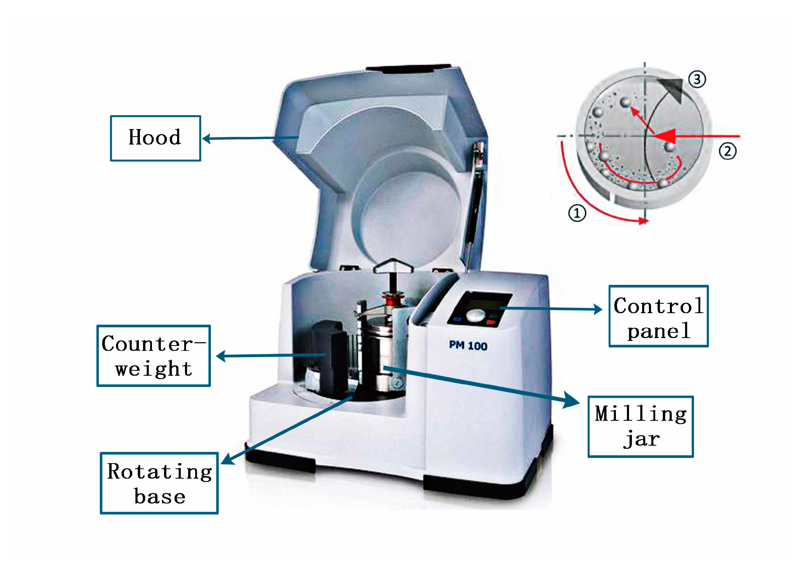
- The milling jar is clamped in the planetary ball mill with the clamping fixture, and the machine cover is covered. The rotating speed is set at 160 rpm, and the milling time is 50 h.
- When the wet ball milling is finished, the powder is dried in a vacuum drying oven and then tested.
- The rotational speed of the ball mill is adjusted to 200, 240, and 280 rpm, and the above steps repeated for the experiment.
2.3. Experimental Equipment
3. Results
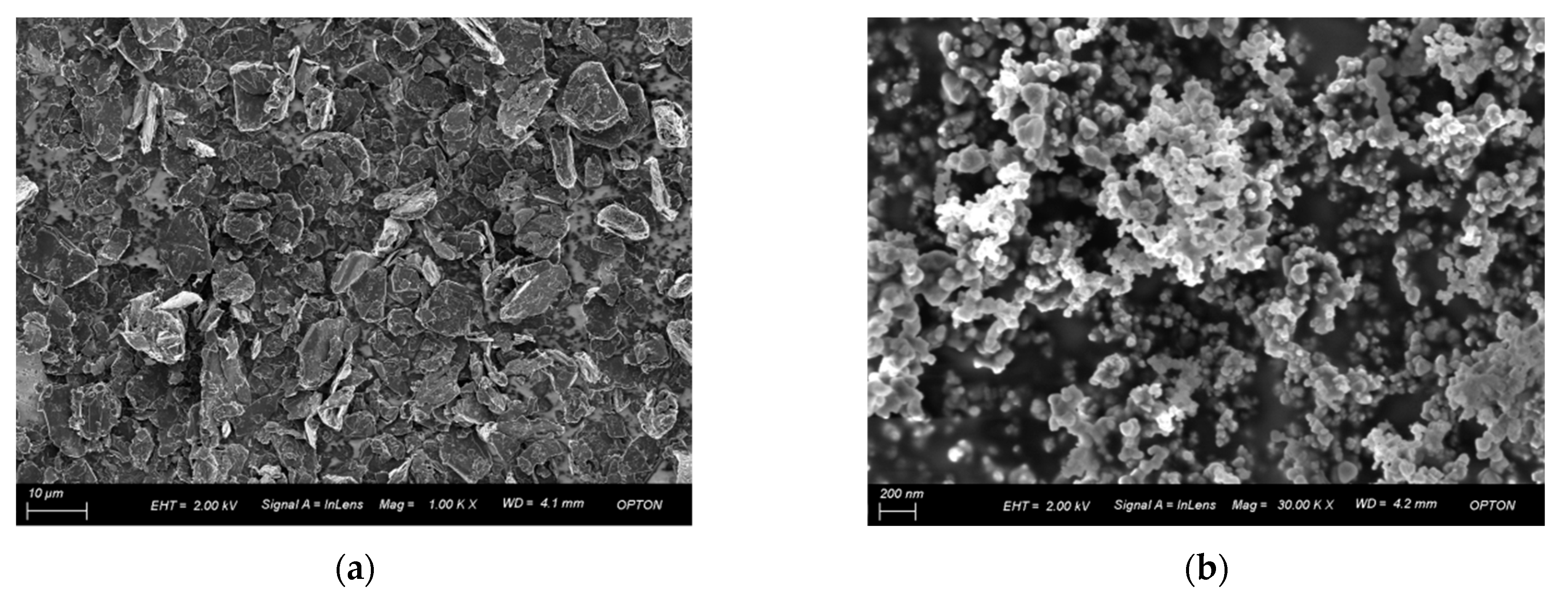
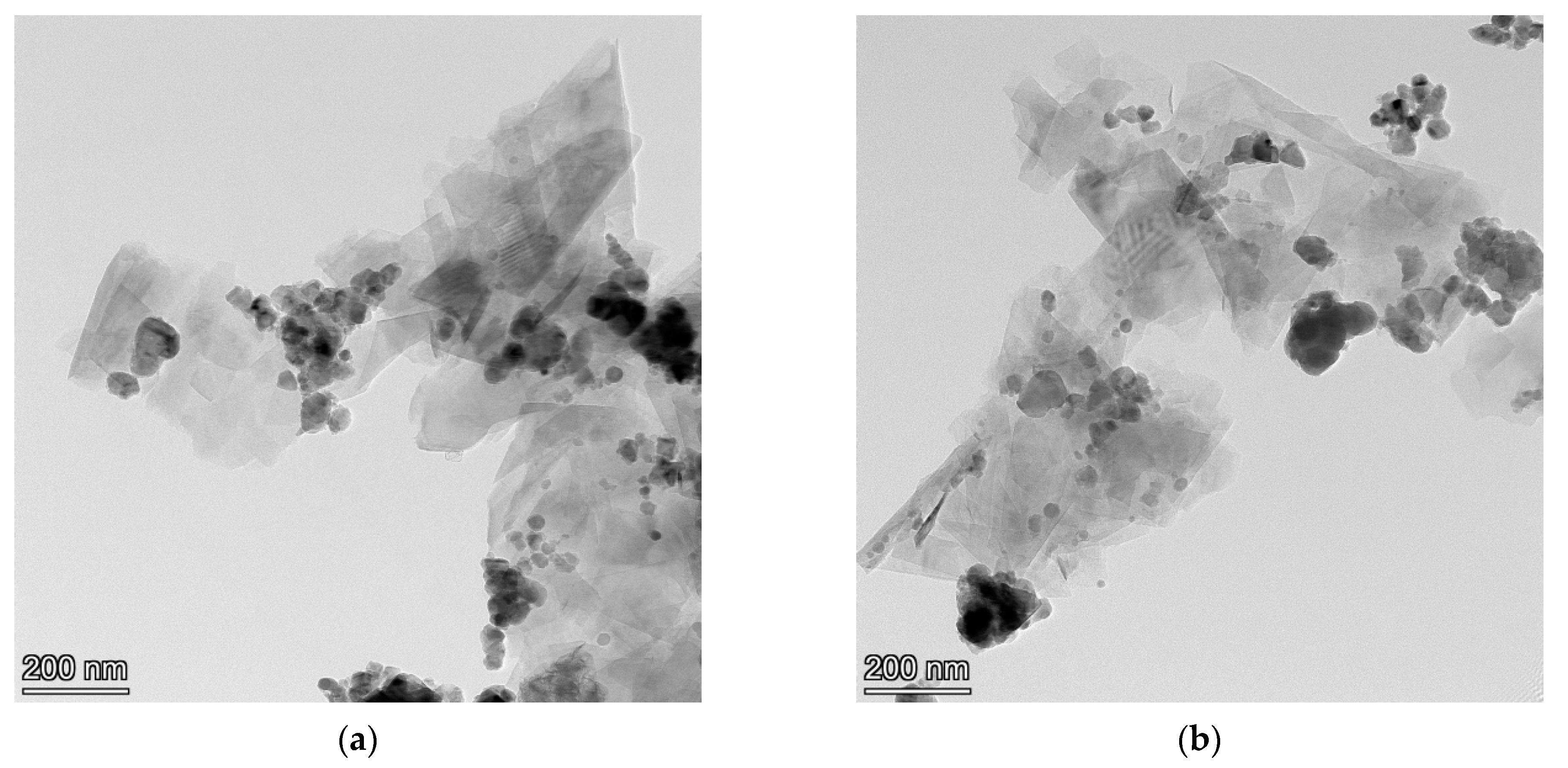
3.1. Surface Morphology of Composite Material before and after Ball Milling
3.2. Dispersion of GNSs and SiC in the Liquid Phase
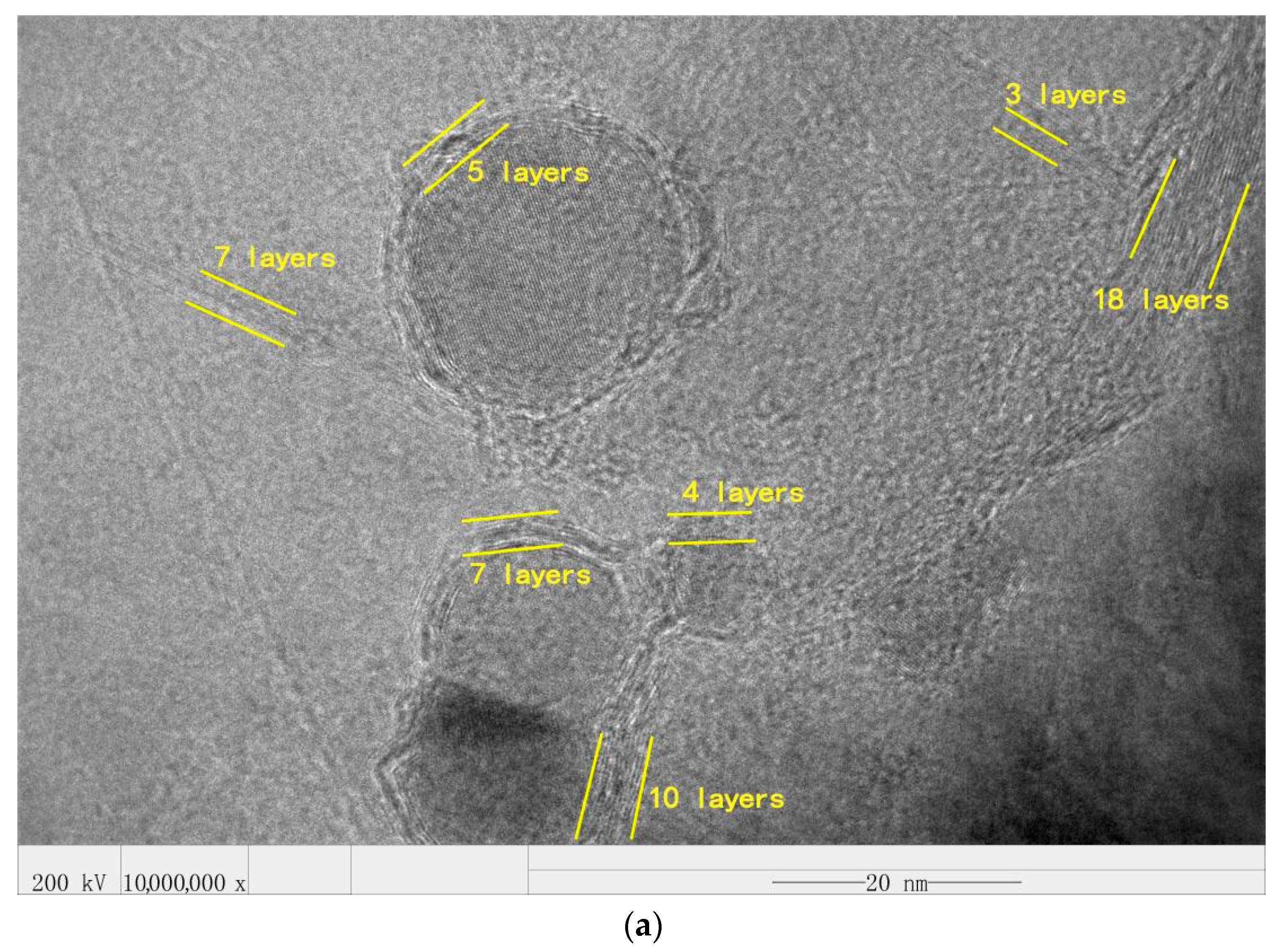
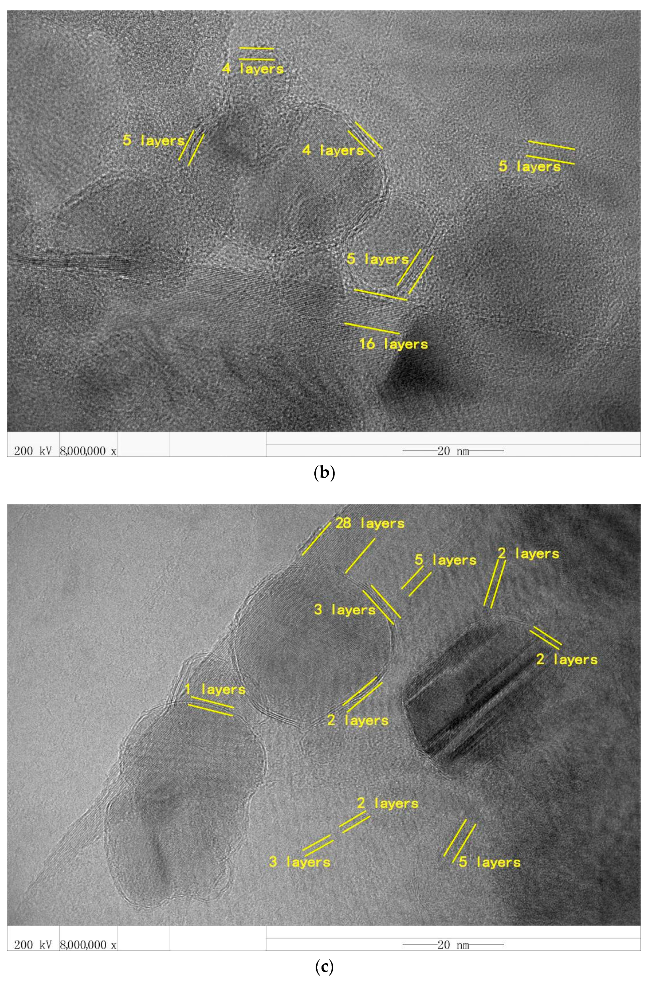
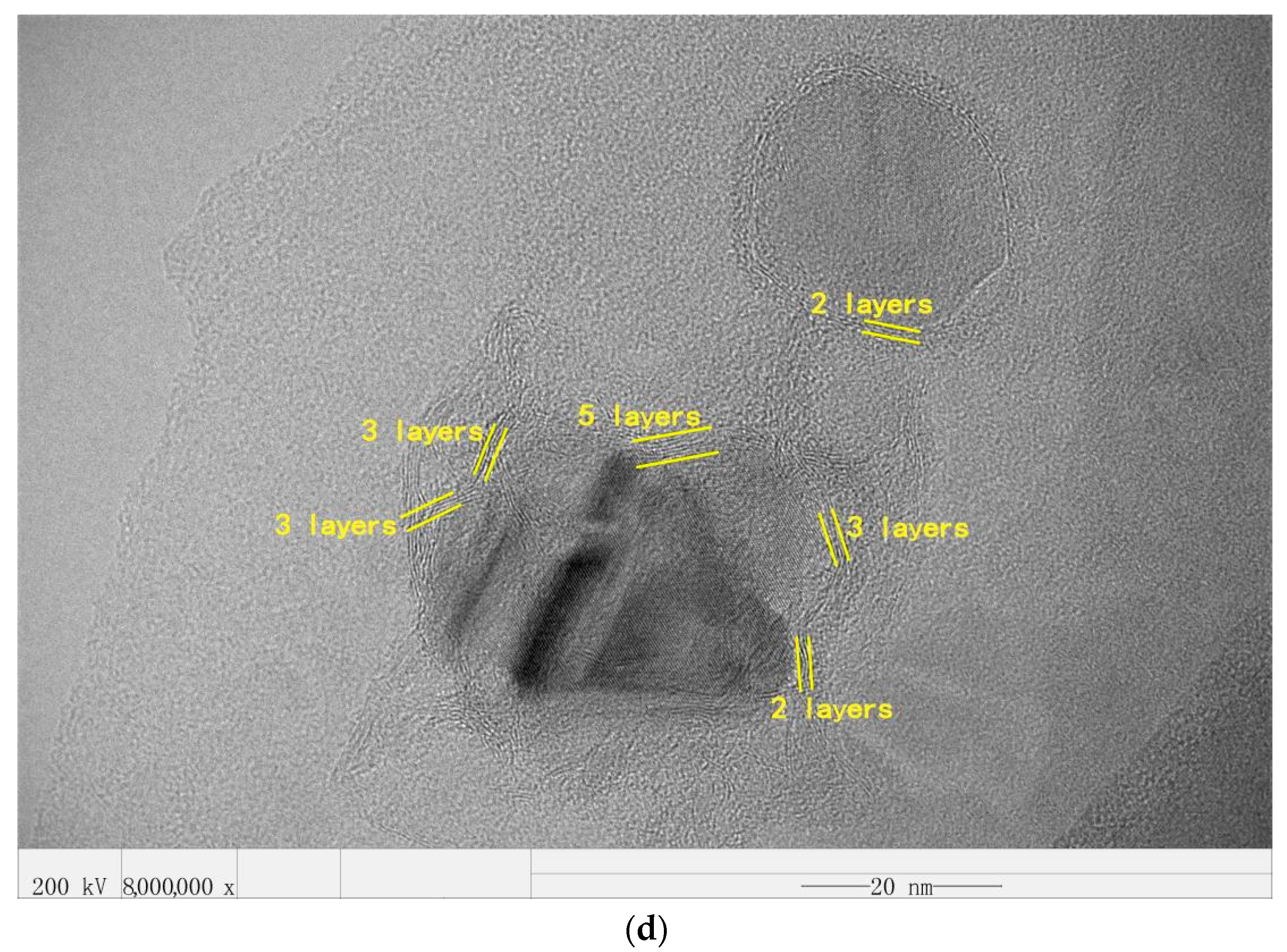
3.3. The Influence of Different Rotational Speeds on the Number of Graphene Layers
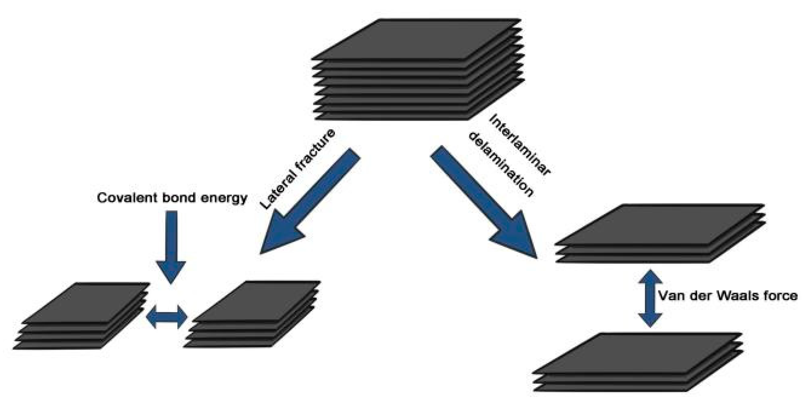
3.3.1. The exfoliation of GNSs in the Presence of SiC Nanoparticles
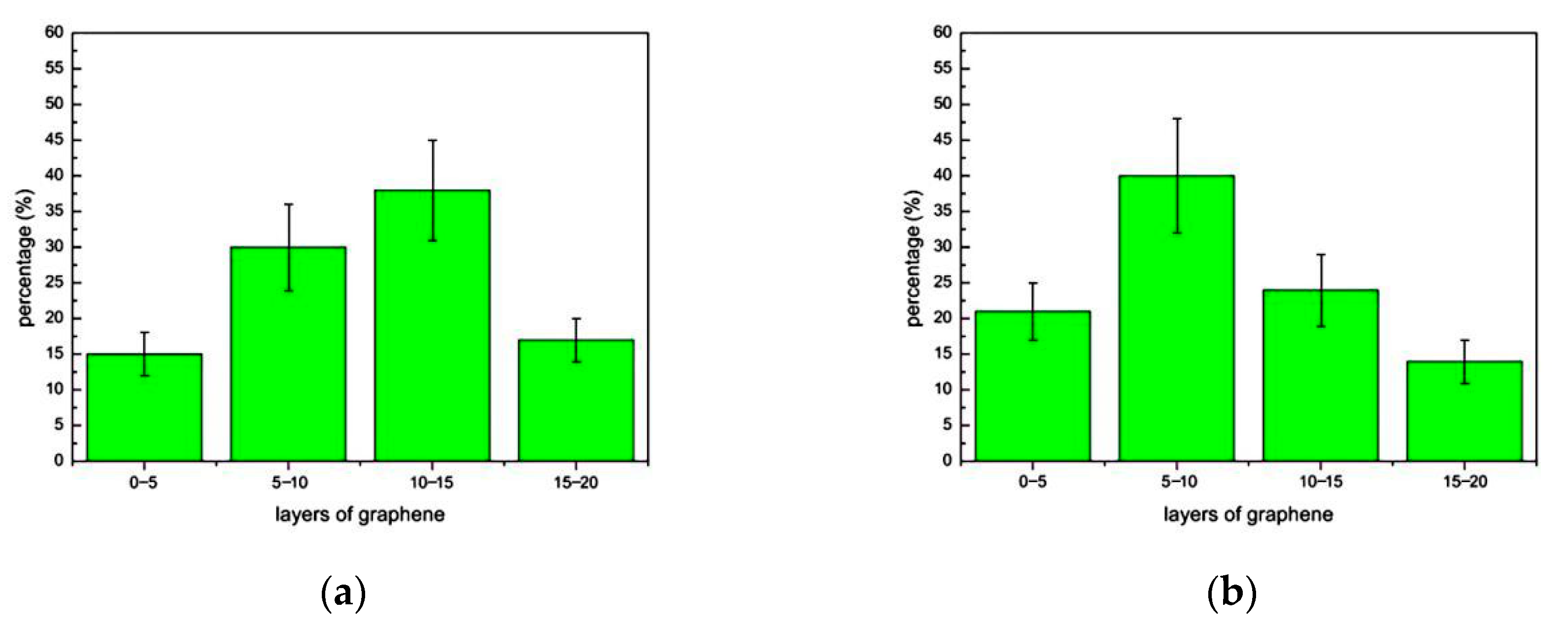
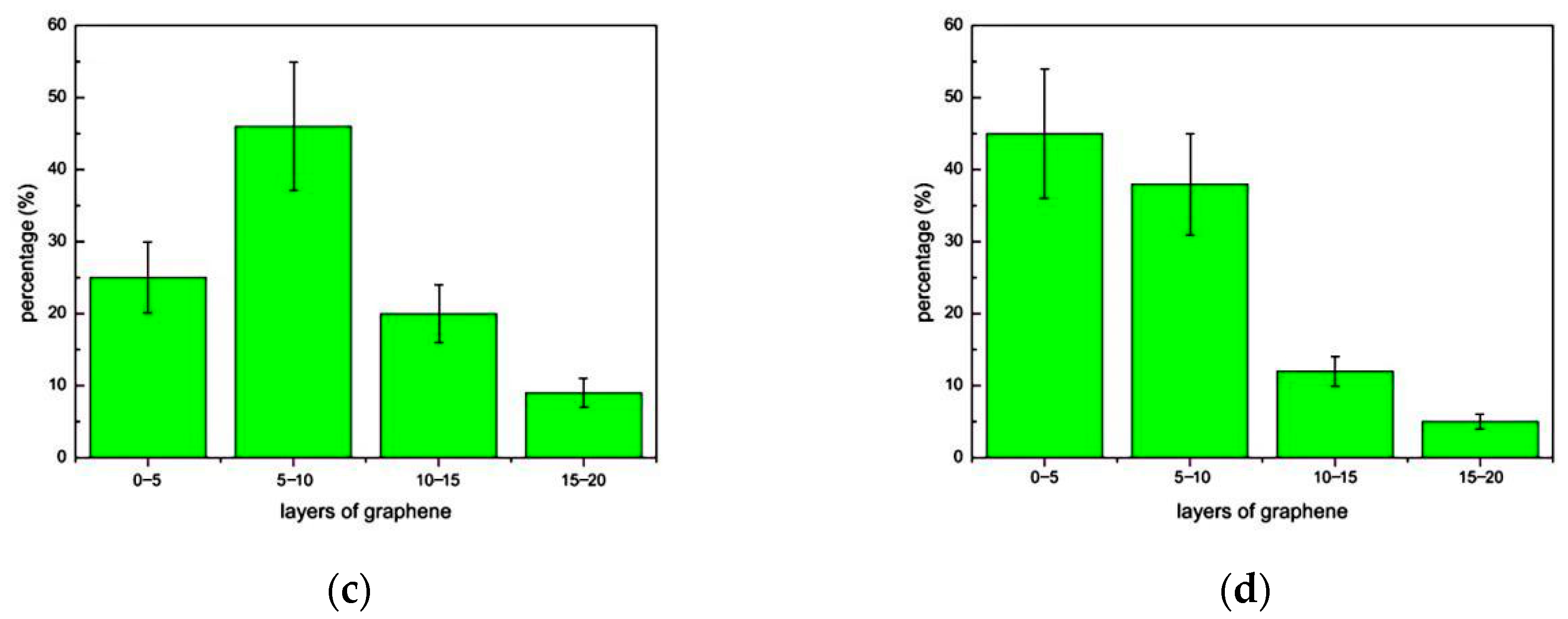
3.3.2. Distribution of Graphene Layers at Different Speeds
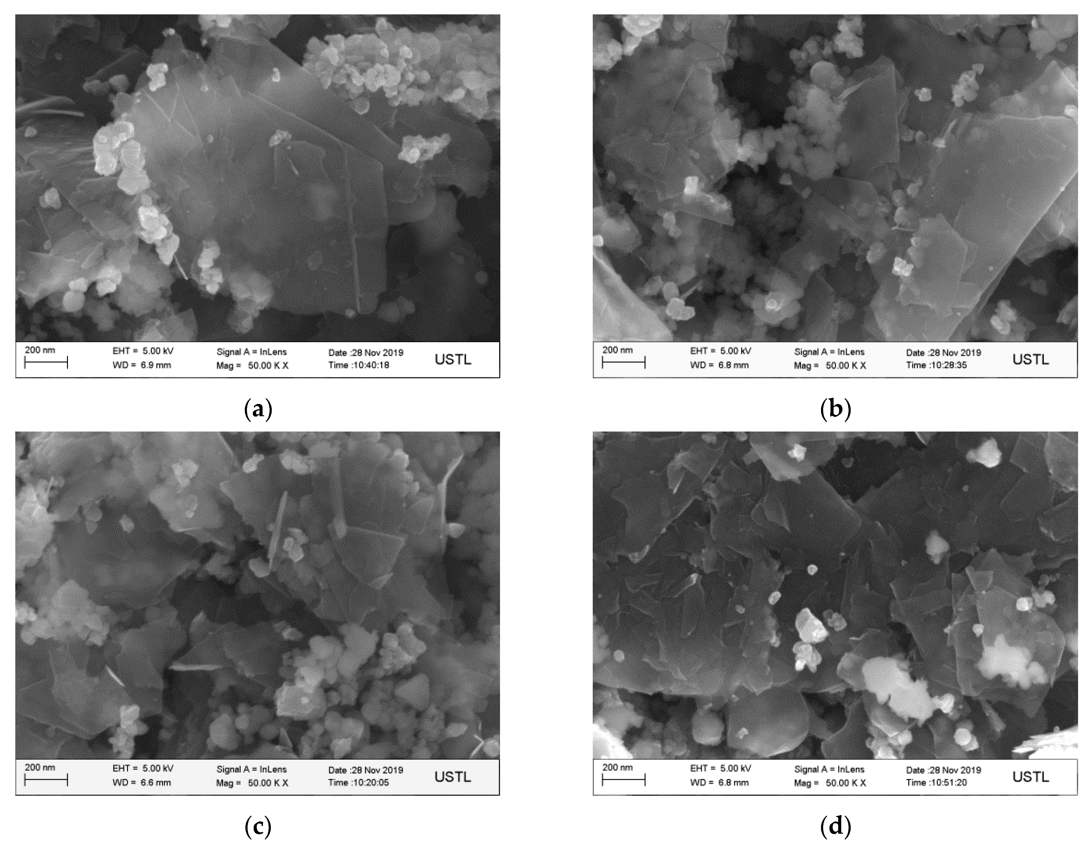
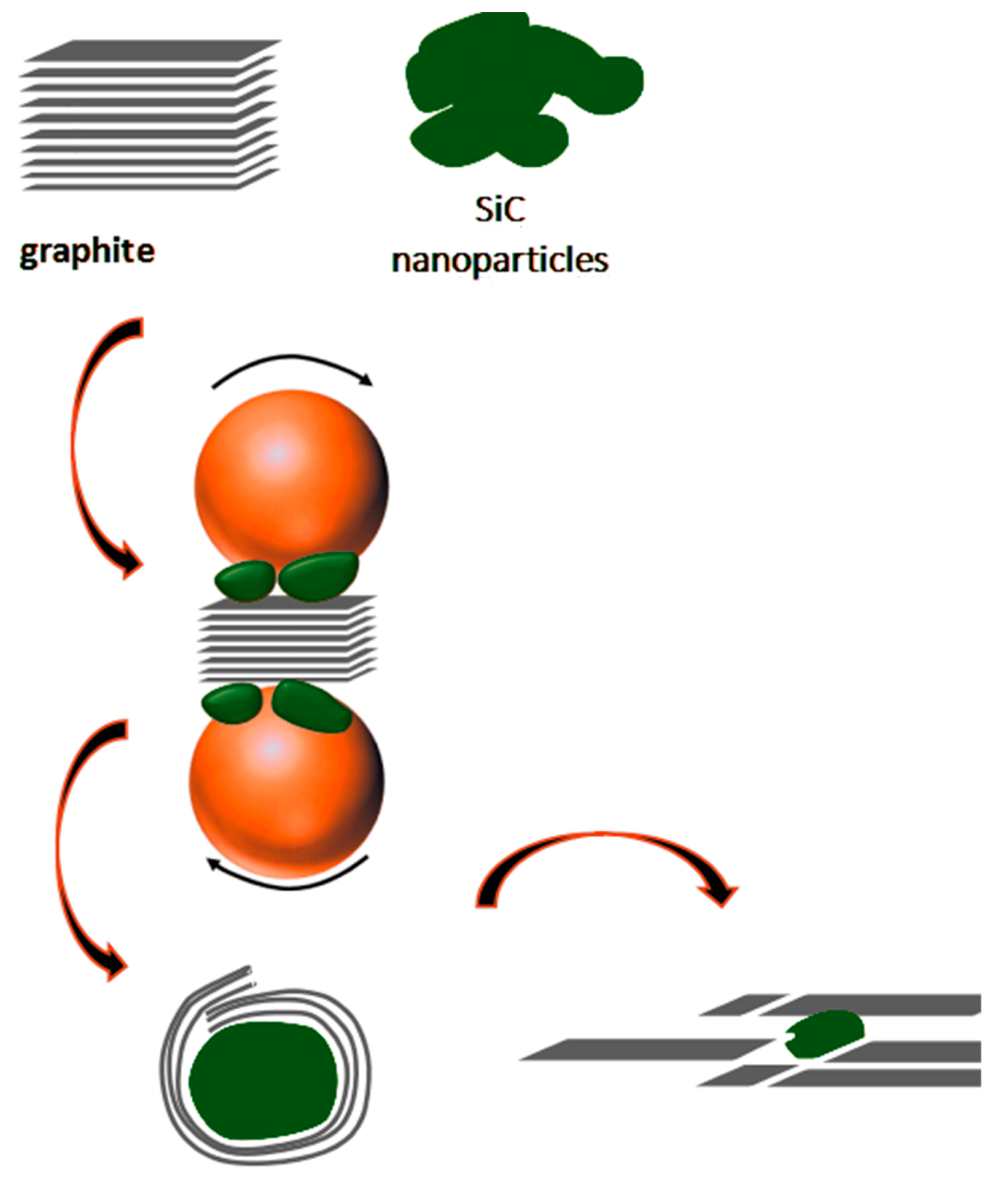
3.3.3. Formation of Core-Shell Structure
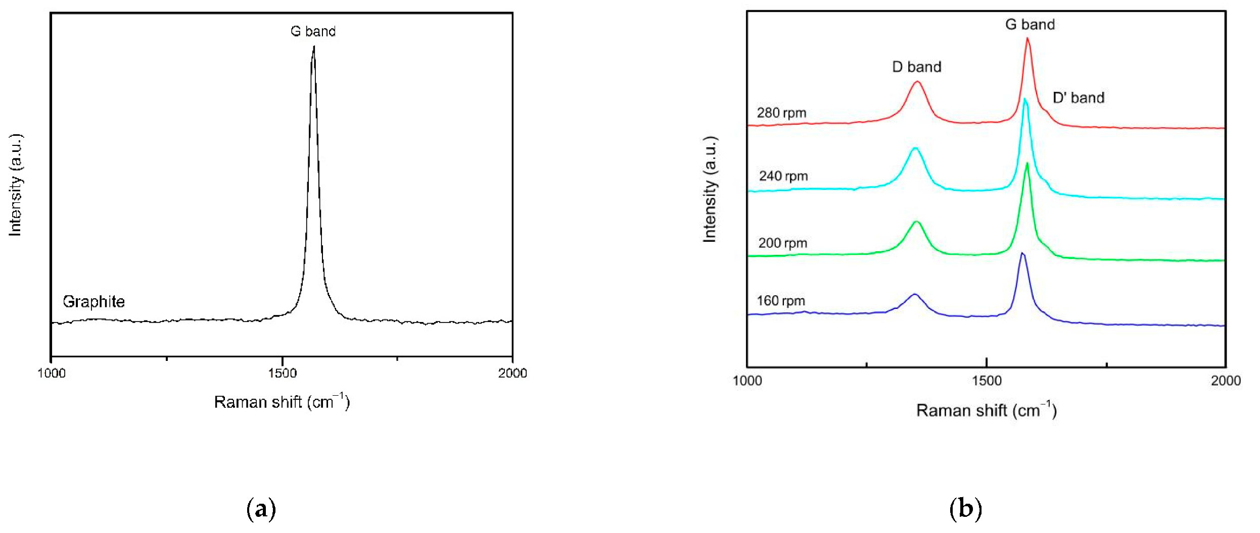
3.4. The Influence of Different Rotational Speeds on the Quality of Graphene
3.5. The Influence of Different Rotational Speeds on the Conversion Efficiency of Graphite Exfoliate to Graphene
4. Conclusions
- The results show that the graphene is well dispersed in SiC nanoparticles when the ball milling speed is in the range of 160–280 rpm, and graphene-wrapped SiC core-shell nanocomposites were synthesized.
- With the increase in ball milling speed, the proportion of few-layer graphene (≤10 layers) increases. When the rotational speed is 160–240 rpm, the proportion of few-layer graphene increases from 45% to about 70%. When the rotational speed is increased to 280 rpm, the proportion of few-layer graphene increases to more than 80%. At the same time, it is found that most of the GNSs wrapped on SiC nanoparticles are ≤7 layers.
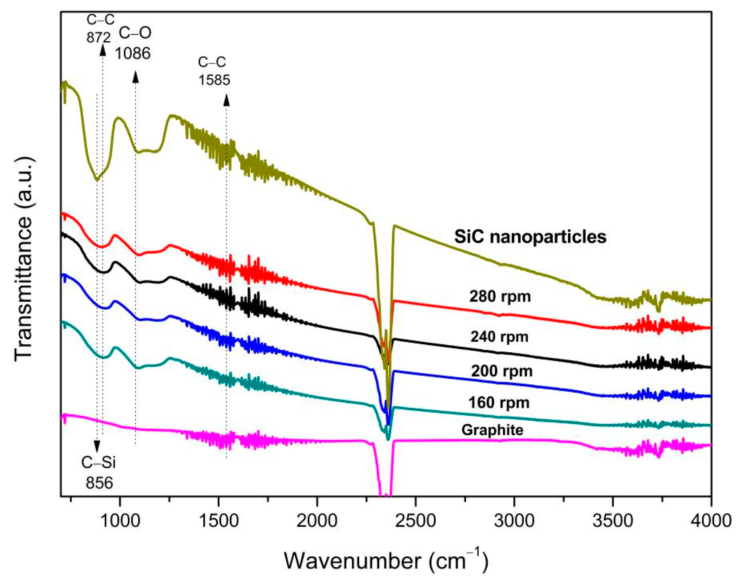
- When the rotational speed is 160–280 rpm, the obtained graphene has relatively small defects, and the defect type is the edge defect that has the least impact on the quality of the graphene and, at the same time, it is almost not oxidized. Therefore, the graphene produced by wet ball milling has better quality.
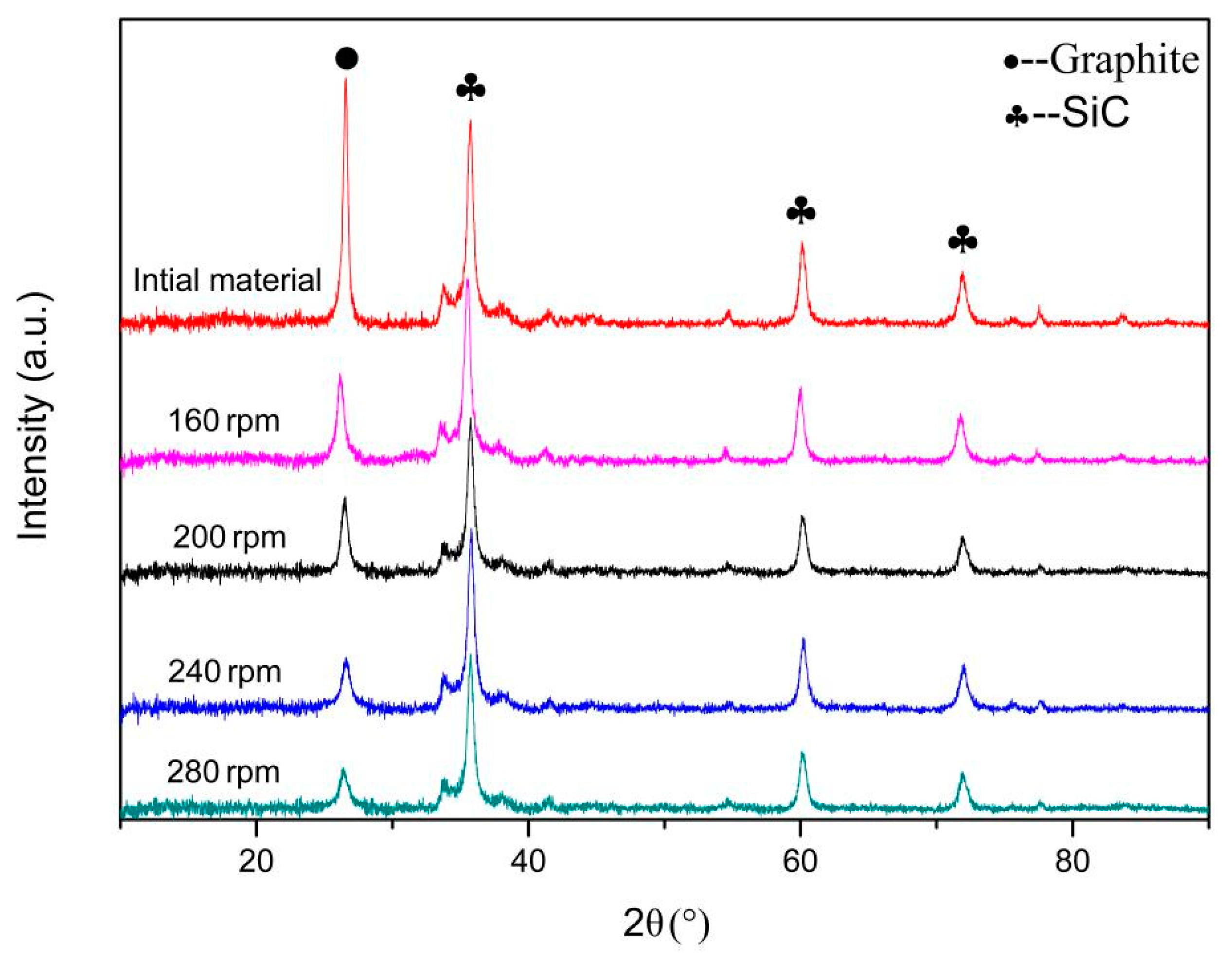
- With the rotational speed increases, the peak intensity of graphite gradually decreases and the conversion efficiency of graphene gradually increases. When the rotational speed reaches 280 rpm, the conversion efficiency of graphene has reached an ideal state.
- The graphene-wrapped SiC core-shell nanocomposites prepared by wet ball milling have high quality. When there are more graphene layers, the anti-friction ability and self-lubricity are stronger. Therefore, in practical application, when the main purpose of the required materials is to reduce friction and wear, a lower ball milling rotational speed can be selected. If the composite material is for the purpose of improving the toughness, thermal conductivity, and optical properties, the ball milling rotational speed can be appropriately increased.
Author Contributions
Funding
Institutional Review Board Statement
Informed Consent Statement
Data Availability Statement
Conflicts of Interest
Nomenclature
| GNSs | graphene nanometer sheets |
| SiC | silicon carbide |
| SEM | scanning electron microscopy |
| HRTEM | high resolution transmission electron microscopy |
| FTIR | Fourier transform infrared spectroscopy |
| XRD | X-ray diffraction |
| A | Hamaker constant |
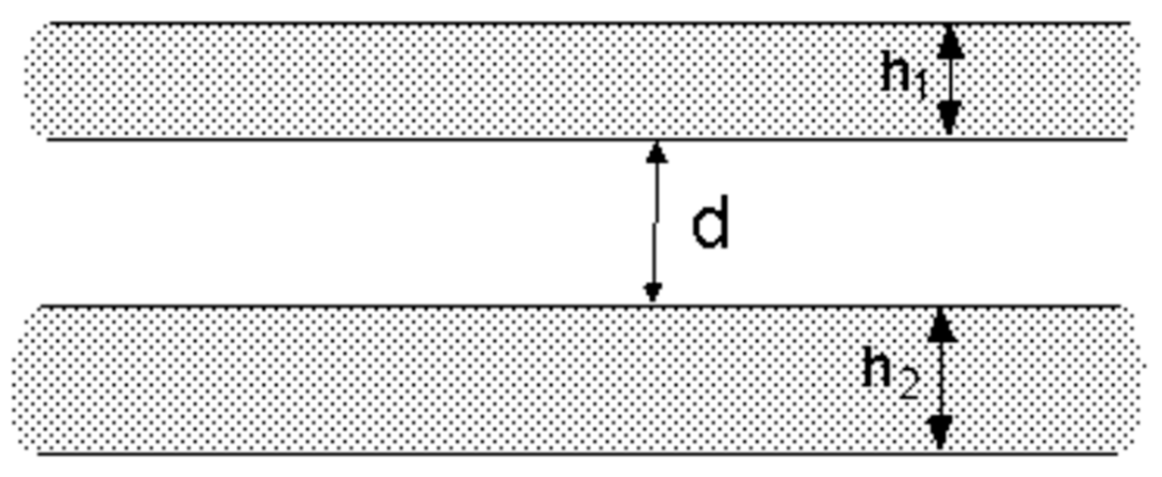
| h1 | thickness of graphite sheet |
| h2 | thickness of single-layer graphene |
| d | distance between two graphite layers |
| ρmm | density of Si3N4 milling ball |
| dmm | The diameter of the milling ball |
| vmm1 | tangential velocity vmm1 of the faster milling media |
| vmm2 | tangential velocity vmm1 of the slower milling media |
| YP | Young’s modulus of the final product |
| Ymm | Young’s modulus of the milling media |
References
- Chen, J.J. Preparation and Properties of SiC-Based Multiphase Conductive Ceramics. Ph.D. Thesis, Shanghai Institute of Ceramics, Shanghai, China, 2018. [Google Scholar]
- Bao, J.W.; Wang, Y.W.; An, R.; Zhang, B.W.; Cheng, H.W.; Wang, F.C. The Effect of Interlayer Materials on Ceramic Damage in SiC/Al Composite Structure. Materials 2020, 13, 3709. [Google Scholar] [CrossRef] [PubMed]
- Fadavi Boostani, A.; Tahamtan, S.; Yazdani, S.; Khosroshahi, R.A.; Wei, D.; Sahamirad, H.; Zhang, X.M.; Jiang, Z.Y. Graphene tweaking hamaker constant of SiC nanoparticles: A new horizon to solve the conflict between strengthening and toughening. Scr. Mater. 2016, 118, 65–69. [Google Scholar] [CrossRef]
- Zhang, J.S.; Yang, S.; Chen, Z.; Wu, H.; Zhao, J.; Jiang, Z.Y. Graphene encapsulated SiC nanoparticles as tribology-favoured nanofillers in aluminium composite. Compos. Part B 2019, 162, 445–453. [Google Scholar] [CrossRef]
- Chen, C.Y. Modification and Preparation of Lead Carbon Supercell. Master’s Thesis, Zhejiang University of Technology, Hangzhou, China, 2014. [Google Scholar]
- Li, W.; Zhang, Y.; Xu, Z.; Yang, A.; Meng, Q.; Zhang, G. Self-assembled graphene oxide microcapsules with adjustable permeability and yolk-shell superstructures derived from atomized droplets. Chem. Commun. 2014, 50, 15867–15869. [Google Scholar] [CrossRef]
- Chen, D.; Yi, R.; Chen, S.; Xu, T.; Gordin, M.L.; Lv, D.; Wang, D. Solvothermal synthesis of V2O5/graphene nanocomposites for high performance lithium ion batteries. Mater. Sci. Eng. B 2014, 185, 7–12. [Google Scholar] [CrossRef]
- Yoo, D.Y.; Tu, N.D.K.; Lee, S.J.; Lee, E.; Jeon, S.R.; Hwang, S.; Lim, H.S.; Kim, J.K.; Ju, B.K.; Kim, H.; et al. Graphene oxide nanosheet wrapped white-emissive conjugated polymer nanoparticles. ACS Nano 2014, 8, 4248–4256. [Google Scholar] [CrossRef] [PubMed]
- Li, Q.; Zhang, Y. Ehanced fracture toughness of pressureless-sintered SiC Ceramics by addition of graphene. J. Mater. Sci. Technol. 2016, 32, 633–636. [Google Scholar] [CrossRef]
- Tang, X.C.; Meng, L.Y.; Zhan, J.M.; Jian, W.R.; Li, W.H.; Yao, X.H.; Han, Y.L. Strengthening effects of encapsulating graphene in sic particle-reinforced al-matrix composites. Comput. Mater. Sci. 2018, 153, 275–281. [Google Scholar] [CrossRef]
- Luo, T.; Chen, X.; Wang, L.; Wang, P.; Li, C.; Iqbal, S.; Cao, B. Ultrafast synthesis of SiC@graphene nanocomposites by one-step laser induced fragmentation and decomposition. Ceram. Int. 2018, 44, 19028–19032. [Google Scholar] [CrossRef]
- Goyenola, C.; Stafstrom, S.; Hultman, L.; Gueorgui, K. Structural Patterns Arising during Synthetic Growth of Fullerene-Like Sulfocarbide. J. Phys. Chem. C 2012, 116, 21124–21132. [Google Scholar] [CrossRef]
- Gueorguiev, G.K.; Pacheco, J.M. Shapes of cagelike metal carbide clusters: First-principles calculations. Phys. Rev. B 2003, 68, 10313–10317. [Google Scholar] [CrossRef]
- Wang, W.; Gai, Y.; Song, N.; Xiao, D.; Tan, H.; Zhao, Y. Highly efficient production of graphene by an ultrasound coupled with a shear mixer in supercritical CO2. Ind. Eng. Chem. Res. 2018, 57, 16701–16708. [Google Scholar] [CrossRef]
- Wang, W.; Gai, Y.; Xiao, D.; Tan, H.; Zhao, Y. A facile and general approach for production of nanoscrolls with high-yield from two-dimensional nanosheets. Sci. Rep.-UK 2018, 8, 15262. [Google Scholar]
- Gai, Y.; Wang, W.; Xiao, D.; Tan, H.; Lin, M.; Zhao, Y. Reversible conversion between graphene nanosheets and graphene nanoscrolls at room temperature. RSC Adv. 2018, 8, 9749–9753. [Google Scholar] [CrossRef]
- Ouyang, L.; Guo, L.; Cai, W.; Ye, J.; Hu, R.; Liu, J.; Yang, L.; Zhu, M. Facile synthesis of Ge@FLG composites by plasma assisted ball milling for lithium ion battery anodes. Mater. Chem. A 2014, 2, 11280–11285. [Google Scholar] [CrossRef]
- Gorrasi, G.; Bugatti, V.; Milone, C.; Mastronardo, E.; Piperopoulos, E.; Iemmo, L.; Bartolomeo, A.D. Effect of temperature and morphology on the electrical properties of pet/conductive nanofillers composites. Compos. Part B 2018, 135, 149–154. [Google Scholar] [CrossRef]
- Zhang, J.S.; Yang, S.; Chen, Z.; Yan, Y.; Zhao, J.; Jiang, Z.Y. In situ synthesis of SiC-graphene core-shell nanoparticles using wet ball milling. Ceram. Int. 2018, 44, 8283–8289. [Google Scholar] [CrossRef]
- Zhao, J.; Liu, M.; Chang, J.X.; Shao, Y.L.; Liu, B.; Liu, R.Z. Controllable synthesis of SiC@Graphene core-shell nanoparticles via fluidized bed chemical vapor deposition. J. Am. Ceram. Soc. 2020, 103, 5579–5585. [Google Scholar] [CrossRef]
- Chen, C.; Han, X.C.; Shen, H.H.; Tan, Y.Q.; Zhang, H.B.; Qin, Y.; Peng, S.M. Preferentially oriented SiC/graphene composites for enhanced mechanical and thermal properties. Ceram. Int. 2020, 46, 23173–23179. [Google Scholar] [CrossRef]
- Alinejad, B.; Mahmoodi, K. Synthesis of graphene nanoflakes by milling natural graphite together with NaCl in a planetary ball mill. Funct. Mater. Lett. 2017, 10, 3. [Google Scholar] [CrossRef]
- Eva, N.; Genadijs, S.; Elvija, N.; Aleksandrs, K. Production of Foamed Concrete in a Planetary Ball Mill. Key Eng. Mater. 2020, 6003, 311–315. [Google Scholar]
- Li, T. Discussion on the influence factors of ball milling efficiency. Ceramics 2019, 9, 63–68. [Google Scholar]
- Li, Z.Y.; Wang, Y.; Cao, Y.C.; Meng, X.H.; Aamir, R.M.; Lu, W.B.; Suo, Y. Effects of loading rates on mode I interlaminar fracture toughness of carbon/epoxy composite toughened by carbon nanotube films. Compos. Part B 2020, 200, 108270. [Google Scholar]
- Zhao, M. Structure and experimental study of graphene prepared by mechanical method. Kunming Univ. Sci. Technol. 2018, 25–26. [Google Scholar]
- Rafael, T. The London-van der Waals interaction energy between objects of various geometries. Phys. Condens. Matter 2001, 13, 195. [Google Scholar]
- Kwade, A. Determination of the most important milling mechanism in stirred media mills by calculating stress intensity and stress number. Powder Technol. 1999, 105, 382–388. [Google Scholar] [CrossRef]
- Trzesowski, A. On the Isothermal Geometry of Corrugated Graphene Sheets. J. Geom. Phy. 2014, 36, 1–45. [Google Scholar]
- Liu, Z.L.; Xue, Q.Z.; Xing, W. Self-assembly of C H-type hydrogenated graphene. Nanoscale 2013, 5, 11132–11138. [Google Scholar] [CrossRef]
- Wang, Y.J.; Li, Z.X.; Bi, K.D.; Yang, J.K.; Chen, Y.F. Molecular dynamics study on the effect of defects on the friction properties of graphene. J. Tribol. 2016, 5, 599–605. [Google Scholar]
- Lin, Z.Y.; Ji, L.F.; Yan, T.Y.; Xu, Y.B.; Sun, Z.Y. Surface defects state analysis of laser induced graphene from 4H-SiC. J. Mater. Res. Tech. 2020, 9, 5934–5941. [Google Scholar] [CrossRef]
- Cao, A.; Shen, B.; Lin, Q.; Chen, S. Influence of Stone-Wales defect on graphene friction: Pinning effect and wrinkle modification. Comp. Mater. Sci. 2020, 173, 109423. [Google Scholar] [CrossRef]
- Zhou, Z.; Hu, Y.; Shan, X.Y.; Lu, X.H. Raman Spectrum of Epitaxial Graphene Grown on Ion Beam Illuminated 6H-SiC (0001). Chin. Phys. Lett. 2014, 31, 126–129. [Google Scholar] [CrossRef]
- Zhang, Z.; Zhang, Y. Application of Raman Spectroscopy in the Research of Two-dimensional Material Stereology. China Stereol. Image Anal. 2020, 25, 93–100. [Google Scholar]
- Eigler, S.; Grimm, S.; Enzelberger-Heim, M.; Mueller, P.; Hirsch, A. Graphene oxide: Efficiency of reducing agents. Chem. Commun. 2013, 49, 7391–7393. [Google Scholar] [CrossRef]
- Lv, Y.; Yu, L.; Jiang, C.; Chen, S.; Nie, Z. Synthesis of graphene nanosheet powder with layer number control via a soluble salt-assisted route. RSC Adv. 2014, 4, 13350–13354. [Google Scholar] [CrossRef]
- Ma, X.; Qu, Q.; Zhao, Y.; Luo, Z.; Zhao, Y.; Ng, K.W. Graphene oxide wrapped gold nanoparticles for intracellular Raman imaging and drug delivery. J. Mater. Chem. B 2013, 1, 6495–6500. [Google Scholar] [CrossRef] [PubMed]
- Hao, H.H.; Liu, J.B.; Li, K.W.; Wang, H.; Yan, H. Research progress in characterization of graphene structure by Raman spectroscopy. Mater. Eng. 2018, 46, 1–10. [Google Scholar]
- Lim, S.Y.; Abdul Mutalib, M.S.; Khaza’ai, H.; Chang, S.K. Detection of fresh palm oil adulteration with recycled cooking oil using fatty acid composition and FTIR spectral analysis. Int. J. Food Prop. 2018, 21, 2428–2451. [Google Scholar] [CrossRef]
- Auge, M.; Haehnlein, B.; Eckstein, M.; Woltersdorf, G.; Pezoldt, J. High Temperature Grown Graphene on SiC Studied by Raman and FTIR Spectroscopy. Mater. Sci. Forum. 2017, 897, 727–730. [Google Scholar] [CrossRef]
- Zhang, L.H. Preparation, Characterization and Electrochemical Properties of Graphene. Master’s Thesis, Tianjin University, Tianjin, China, 2012. [Google Scholar]


Publisher’s Note: MDPI stays neutral with regard to jurisdictional claims in published maps and institutional affiliations. |
© 2021 by the authors. Licensee MDPI, Basel, Switzerland. This article is an open access article distributed under the terms and conditions of the Creative Commons Attribution (CC BY) license (http://creativecommons.org/licenses/by/4.0/).
Share and Cite
Liang, D.; Yan, L.; Huang, K.; Li, Y.; Ai, F.; Zhang, H.; Jiang, Z. Effect of Different Rotational Speeds on Graphene-Wrapped SiC Core-Shell Nanoparticles in Wet Milling Medium. Materials 2021, 14, 944. https://doi.org/10.3390/ma14040944
Liang D, Yan L, Huang K, Li Y, Ai F, Zhang H, Jiang Z. Effect of Different Rotational Speeds on Graphene-Wrapped SiC Core-Shell Nanoparticles in Wet Milling Medium. Materials. 2021; 14(4):944. https://doi.org/10.3390/ma14040944
Chicago/Turabian StyleLiang, Dong, Ling Yan, Kunkun Huang, Yan Li, Fangfang Ai, Hongmei Zhang, and Zhengyi Jiang. 2021. "Effect of Different Rotational Speeds on Graphene-Wrapped SiC Core-Shell Nanoparticles in Wet Milling Medium" Materials 14, no. 4: 944. https://doi.org/10.3390/ma14040944
APA StyleLiang, D., Yan, L., Huang, K., Li, Y., Ai, F., Zhang, H., & Jiang, Z. (2021). Effect of Different Rotational Speeds on Graphene-Wrapped SiC Core-Shell Nanoparticles in Wet Milling Medium. Materials, 14(4), 944. https://doi.org/10.3390/ma14040944