1. Introduction
1.1. 3D Printing Technology for Construction
Additive manufacturing (AM), which is also referred to as three-dimensional (3D) printing, is a concept that contrasts with subtractive manufacturing (SM), where material production is realized by cutting or trimming [
1]. In ASTM F 2792-12 (2015), AM is defined as “a method of stacking continuous materials layer-by-layer to create geometry from 3D model data, which is a technology that contrasts SM [
2,
3,
4]”.
The application range of 3D printing technology and materials has been extended to daily necessities, machinery, electronics, and medicine. Experts in these fields have collaborated closely with construction technology engineers to create high-value- construction applications using 3D printing for geometries that are difficult to implement with existing methods, such as atypical members and geometry optimization [
5,
6].
Representative 3D printing technologies used in the construction field include material extruded 3D printing (ME3DP) and binder jetting 3D printing (BJ3DP). ME3DP is a method of extruding construction materials, such as mortar and concrete, from a nozzle using pressure. It is mainly used on-site for the construction of large members such as columns and walls owing to its advantages of easy on-site 3D printing and enlargement [
7]. BJ3DP is a method of forming 3D structures through bonding between powder particles by discharging a liquid adhesive on a powder-type material. Compared with ME3DP, it has the advantage of implementing geometrical and topology-optimized structures because of its high degree of freedom in the geometry of architectural construction [
8,
9,
10].
The structures printed using a 3D printer must meet specific mechanical performance requirements. It has been reported that the materials used and the build orientation affect the mechanical performance of the 3D output [
11,
12,
13,
14]. Several studies have been conducted examining the mechanical performance of the output and its relation to the build orientation, but they are limited to the evaluation of short-term performance, such as compressive strength [
15,
16], tensile strength [
17,
18], flexural strength [
19], and shear strength [
20].
The printability and mechanical properties of 3D printing concrete have been widely investigated in laboratories. Furthermore, optimizations are being performed to improve the mechanical properties of 3D printed concrete, including the interlayer strength. For this purpose, mesh reinforcing [
21] and 3D concrete printing with a reinforcing bar [
22], fibers [
23], or admixtures [
24] have been employed.
1.2. Binder Jetting 3D Printing
A number of studies examined physical performance based on the material. For example, Gibbons et al. used rapid hardening cement (RHC) [
25], Maier et al. used calcium aluminate cement [
26], and Cesaretti et al. used magnesium oxide cement [
27] for BJ3DP. The list of materials that can be used for BJ3DP has been continuously expanding.
In this study, ProJet CJP 360 from 3D Systems was used. The build volume of the device is 203 mm × 254 mm × 203 mm, and two to four layers can be deposited per minute with a thickness of 0.089–0.102 mm for each layer. BJ3DP deposits powder by injecting a liquid binder into a powder bed [
28,
29] and draws a 2D pattern by applying a layer of powder to a build plate and injecting the liquid adhesive binder into specific parts [
30,
31].
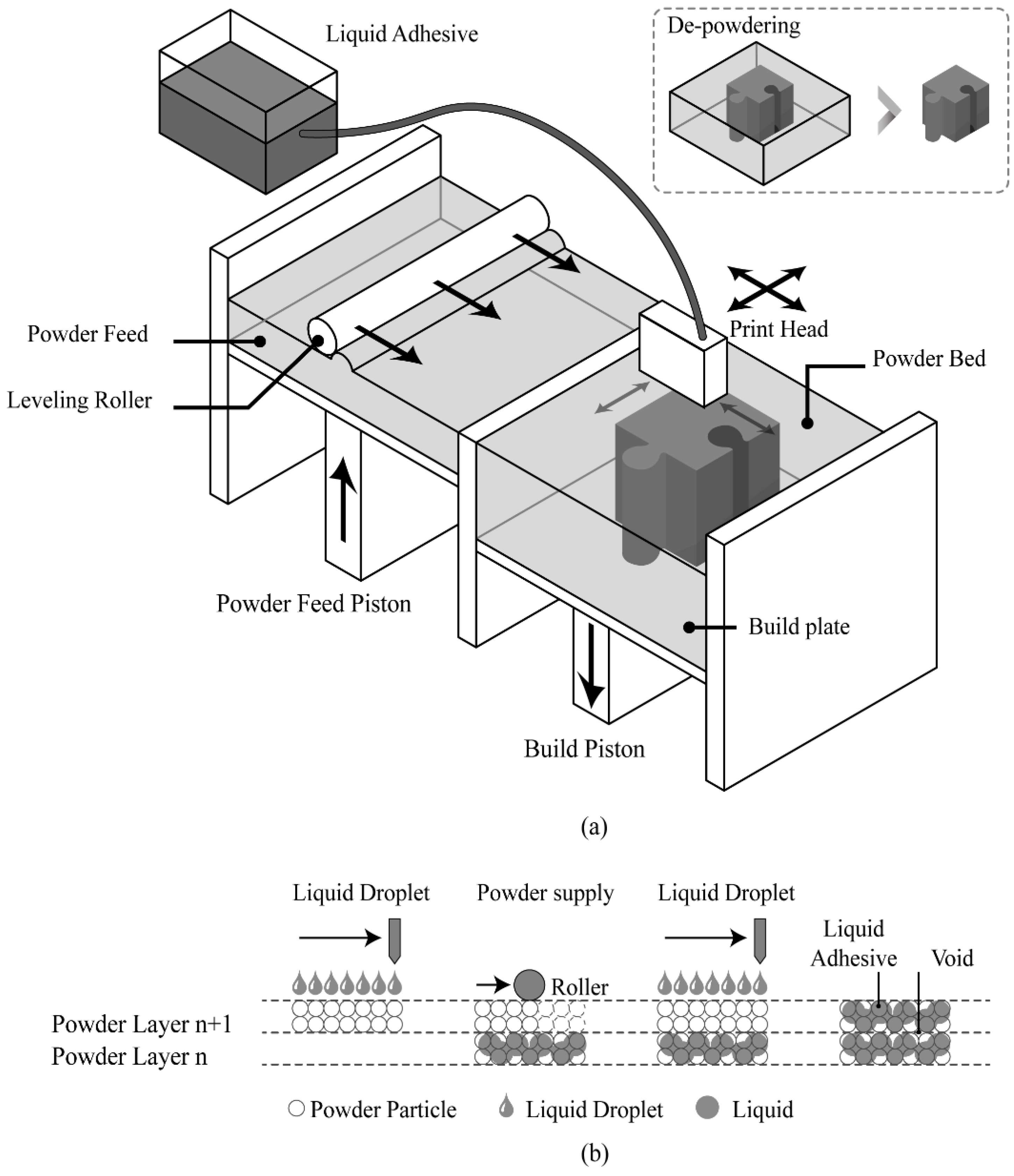
A schematic of the BJ3DP process is illustrated in
Figure 1a [
32]. The setting of the 3D printer is spread over the bed surface of the powder by the leveling roller corresponding to the thickness of the layer (approximately 0.1 mm). Subsequently, a print head jets the liquid adhesive binder to the powder bed to create a 2D pattern on the layer. The binder droplets thus formed are selectively applied to the powder layer, thus binding the powder particles with each other (
Figure 1b). After each layer is spread, the build piston is lowered to accommodate the next layer, and the process is repeated.
After the 3D output is obtained by repeating this process, the unbound powder is removed. When cementitious materials are used in BJ3DP, performance improvement after processing is essential because the mechanical performance immediately after printing is low [
33,
34,
35].
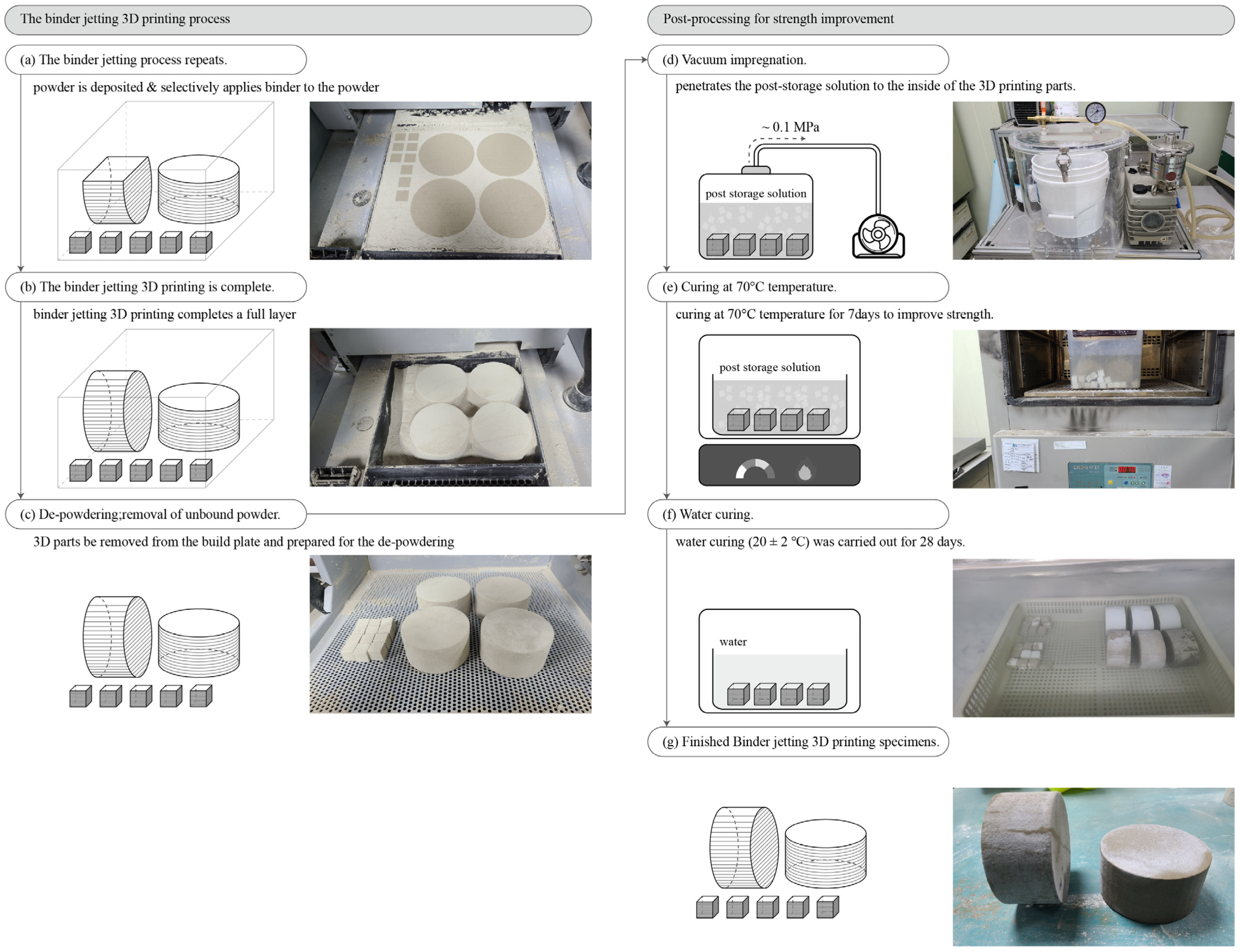
Figure 2 shows the binder jetting 3D printing process and postprocessing for strength improvement.
Figure 2a–c shows the binder jetting 3D printing process;
Figure 2a shows the selectively applied binder to the powder surface in a specific layer, whereas
Figure 2b shows the completed 3D printing output until the final layer. Furthermore,
Figure 2c shows the output after depowdering.
Figure 2d–g shows the postprocessing for strength improvement. The test specimens were manufactured through vacuum impregnation, temperature curing at 70 °C, and water curing.
1.3. Introduction of Chloride Diffusion for Durability Evaluation
Steel-reinforcing-bar corrosion caused by chloride penetrating concrete is recognized as the major factor that causes the deterioration of concrete structures [
36]. Reinforcing bar corrosion causes concrete cracks and cladding, resulting in a significant reduction in the strength of the structure [
37,
38].
A technology for inserting reinforcing bars into 3D printed concrete has recently been developed [
39,
40]. An experimental study is therefore needed to confirm the corrosion of the reinforcing bar caused by chloride. In particular, it is reported that 3D printed concrete is mainly implicated in the differential degradation of durability depending on the build orientation [
41]. Chloride penetration in MD3DP concrete has been investigated in previous studies [
42,
43]. However, BJ3DP concrete has not been studied thus far. Therefore, this study aimed to evaluate the chloride penetration in BJ3DP according to the build orientation.
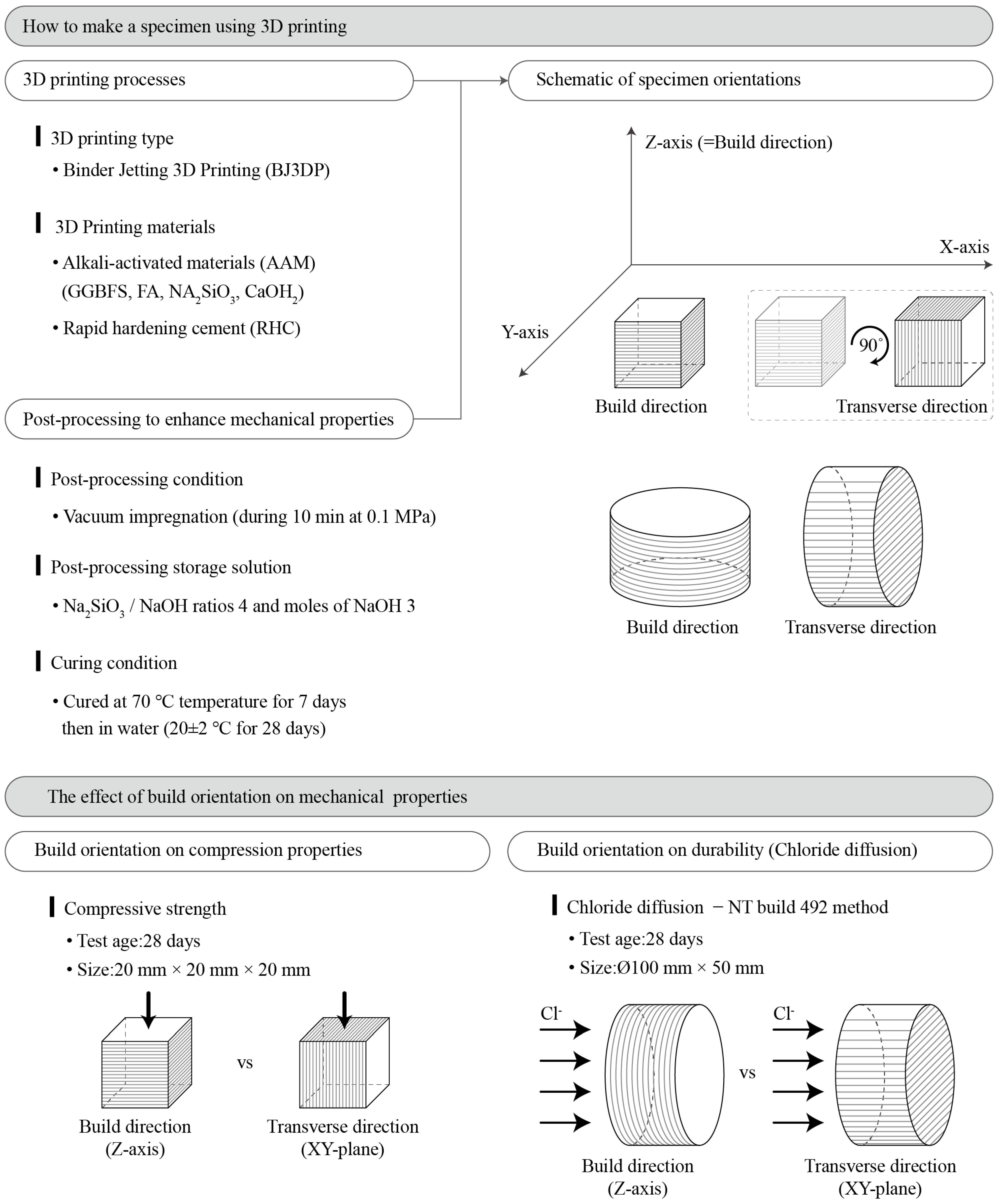
1.4. Research Objectives
Recently, 3D printer output has been used as a building member. However, methods and research results for evaluating the durability of printouts have not been reported. To utilize the cementitious material-based 3D printing output as a building member for long-term use rather than a prototype for temporary use, its long-term durability performance should be examined in addition to its short-term mechanical performance. As a step in this direction, the chloride diffusion coefficient was evaluated in this study using NT build 492 [
44], a representative method for evaluating the durability of cementitious materials. Additionally, the influence of the build orientation (build and transverse directions) on chloride diffusion was evaluated.
Figure 3 shows a schematic of the research plan and the purpose of this study.
2. Materials and Methods
2.1. Materials Used
2.1.1. Powder and Binder
For cementitious materials used for binder jetting, rapid reactions and hardening are essential when an adhesive is injected [
45,
46,
47]. Therefore, in this study, alkali-activated materials (AAMs) and RHC were used to rapidly harden through reactions with water and develop the required strength after printing.
Table 1 lists the physical properties and chemical compositions of the materials used. According to the literature, the injection of VisiJet
® PXL, an adhesive for ProJet CJP 360 [
48], onto cementitious materials further decreases the compressive strength, compared with the injection of ordinary distilled water as an adhesive [
32,
49]. Thus, ordinary distilled water was injected as an adhesive in this study.
2.1.2. Mixture Design
In a previous study [
32], a basic methodology was developed for alkali-activated materials (AAM)-based BJ3DP. We used AAM comprising ground granulated blast-furnace slag (GGBFS) and fly ash (FA) as the major components of the BJ3DP powder. The AAM powder was synthesized using an optimal mixture ratio described in a previous report [
32]. Silica sand with a size of 0.1–0.17 mm was mixed with AAMs and RHC. BJ3DP mortar specimens were printed using a binder (powder) with a silica sand ratio of 0.75:0.25.
Table 2 lists the binder compositions.
2.1.3. Postprocessing
Compressive strength specimens (20 mm × 20 mm × 20 mm) and durability (ϕ100 mm × 50 mm) specimens were produced using BJ3DP, and postprocessing was performed for strength improvement. A post-storage solution was prepared by mixing liquid sodium silicate (SiO
2 28.2%, Na
2O 9.3%, and H
2O 65.5%) and pure 98% sodium hydroxide (NaOH) (Na
2SiO
3/NaOH ratio of 4 and 3 mol of NaOH).
Table 3 shows the composition of the mixed poststorage solution. The poststorage solution was prepared using the optimal mixture ratio reported in the previous study [
32].
Postprocessing was performed using the following method [
37,
38]. The outputs were printed and dried for 2 h in a powder bed. After 24 h, depowdering was carried out using a compressed air gun to remove any unbound powder. Subsequently, a basic postprocessing procedure was carried out as follows: (1) The BJ3DP output was immersed in the postprocessing storage solution in a vacuum impregnator. (2) A maximum pressure of 0.10 MPa was maintained, and the postprocessing solution permeated the voids inside the printed output. (3) Vacuum impregnation was continued until no air bubbles were produced in the printed output, which in this case required ~10 min. (4) The output was immersed in the postprocessing storage solution in a temperature chamber at 70 °C for 7 days. (5) The output was removed from the postprocessing solution and wiped off with distilled water to remove any remaining solution from its surface. (6) After curing in a 70 °C temperature chamber for 7 days, water curing (20 ± 2 °C) was carried out for 28 days [
32].
2.2. Experimental Method
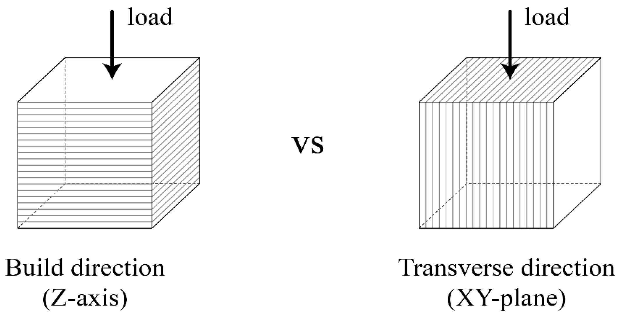
2.2.1. Compressive Strength
To examine the influence of the build orientation on the mechanical performance of the 3D printer outputs, loads were applied in the build and transverse directions, as shown in
Figure 4. Compressive strength specimens were fabricated through the postprocessing procedure described in
Section 2.1.3 after printing cubic specimens with a size of 20 mm × 20 mm × 20 mm. Compressive strength was tested according to the Korean Industrial Standards of KS L ISO 679 [
50] using a universal testing machine (UTM, Instron Universal Testing Machine, MA, USA; maximum load of 50 kN) at 28 days of age. Compressive strength was measured for five specimens of each material in both directions.
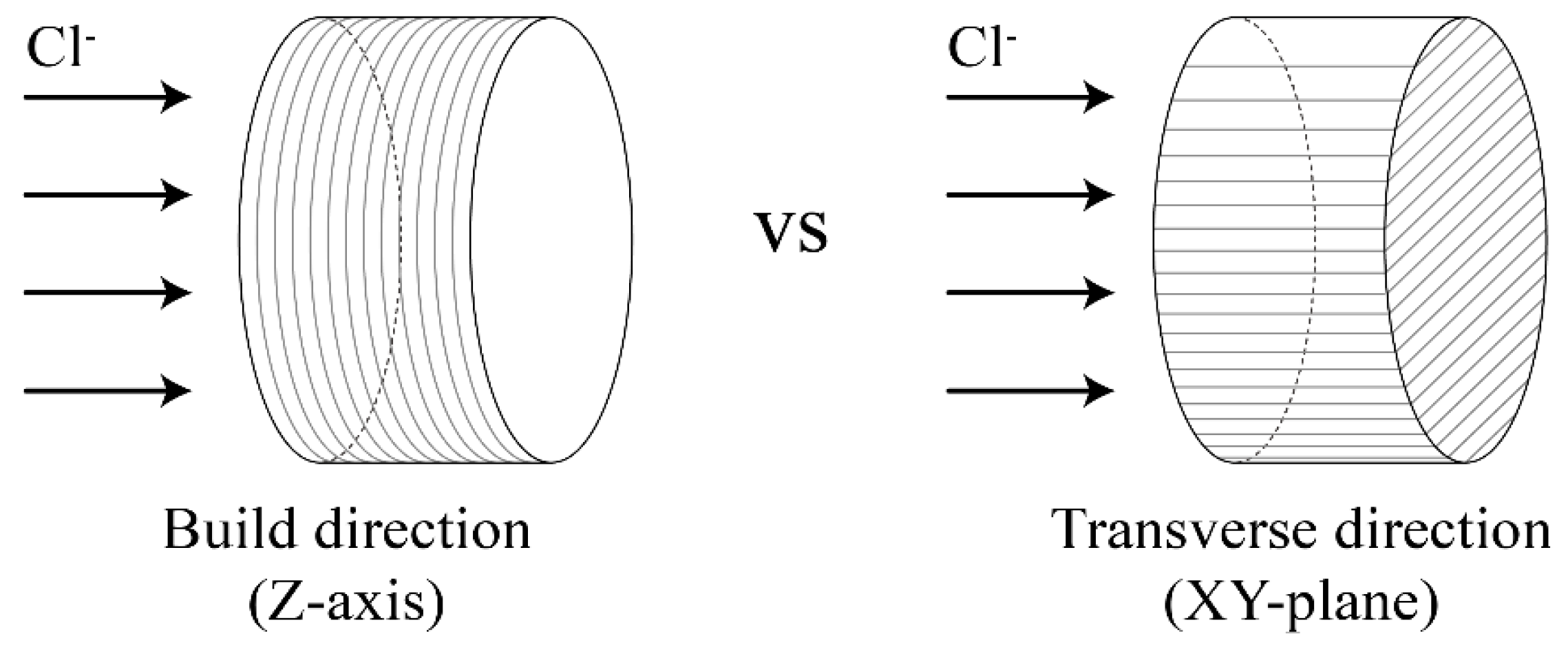
2.2.2. Durability (Chloride Diffusion)
To examine the influence of the build orientation on the durability performance of the 3D printer outputs, a chloride diffusion test was conducted in the build and transverse directions, as shown in
Figure 5. In this study, the chloride diffusion coefficient was evaluated by NT build 492. This coefficient is the chloride migration coefficient from nonsteady state migration experiments [
44], in which an electrically accelerated test method is applied to the DuraCrete model, a representative method to examine the durability of cementitious materials. For the durability test, specimens with a size of ϕ100 mm × 50 mm were fabricated through the postprocessing procedure described in
Section 2.1.3 after printing. The durability was measured using three specimens for each material and direction.
As pretreatment, the specimens were subjected to vacuum saturation (0.10 MPa) for 3 h and then immersed in a saturated solution of calcium hydroxide (Ca(OH)
2) for 18 ± 2 h. In the electrically accelerated test, an electrical potential difference was applied by filling the anode (+) with a 0.3 M NaOH aqueous solution and the cathode (−) with a 10% NaCl aqueous solution. The secondary voltage was calculated by applying an initial voltage of 30 V and measuring the current value for the initial voltage. Consequently, a test time of 6 h was determined based on the current value. Upon completion of the test, each specimen was split, and a 0.1N silver nitrate (AgNO
3) aqueous solution was applied. The silver chloride line was then measured using a digital Vernier caliper, and the average value was calculated. The chloride diffusion coefficient was calculated using Equation (1):
where
is non-steady-state migration coefficient, (
),
is the absolute value of the applied voltage (V),
is the average value of the initial and final temperatures in the anolyte solution (°C),
is the thickness of the specimen (mm),
is the average value of the penetration depths (mm), and
is test duration (hour).
3. Results
3.1. Compressive Strength Test Results
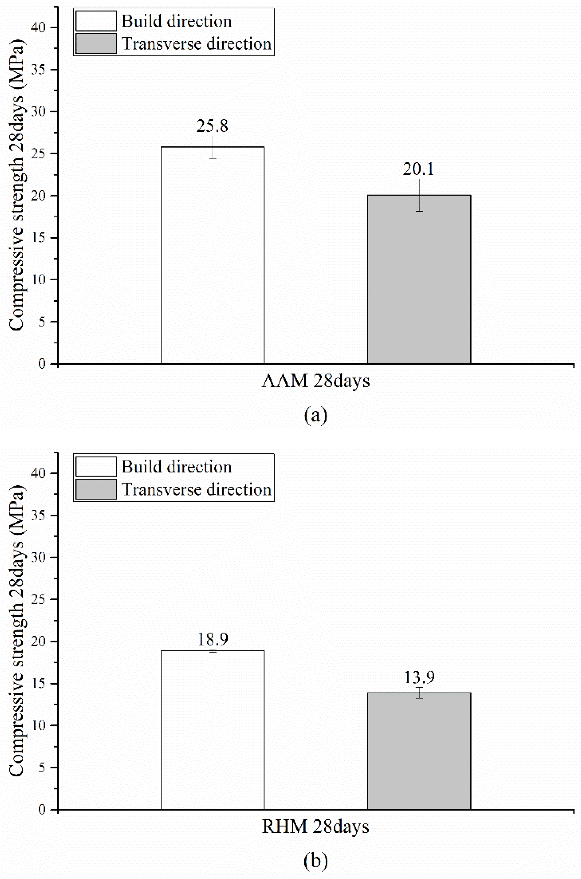
Figure 6 shows the compressive strengths of the BJ3DP specimens with respect to the build orientation at 28 days of age.
Figure 6a shows the compressive strength of the AAM. The measurement results show that the compressive strength was approximately 22.1% lower in the transverse direction, as 25.8 MPa was observed in the build direction and 20.1 MPa in the transverse direction.
Figure 6b shows the compressive strength of the rapid hardening mortar (RHM). The compressive strength was approximately 26.5% lower in the transverse direction than in the build direction, as 18.9 MPa was observed in the build direction and 13.9 MPa in the transverse direction.
It appears that the strength was reduced in the transverse direction because gaps between interlayers were generated in the BJ3DP deposition process. As a result, the mechanical properties of BJ3DP are influenced strongly by the printing direction. Compared with conventional concrete or mortar, the critical problems of the mechanical properties of 3D printed concrete or mortar are the interlayer bond strength and anisotropy. The weak interface bond leads to the reduction of the mechanical properties and durability of 3D printed concrete or mortar [
51]. Therefore, further research should be conducted in the future to improve the interlayer bond strength of BJ3DP.
3.2. Chloride Diffusion Test
Figure 7 and
Figure 8 and
Table 4 show the chloride diffusion coefficient at 28 days of age after the mortar specimens (
) printed using BJ3DP were subjected to postprocessing and curing. In general, the penetration resistance increased as the chloride diffusion coefficient decreased.
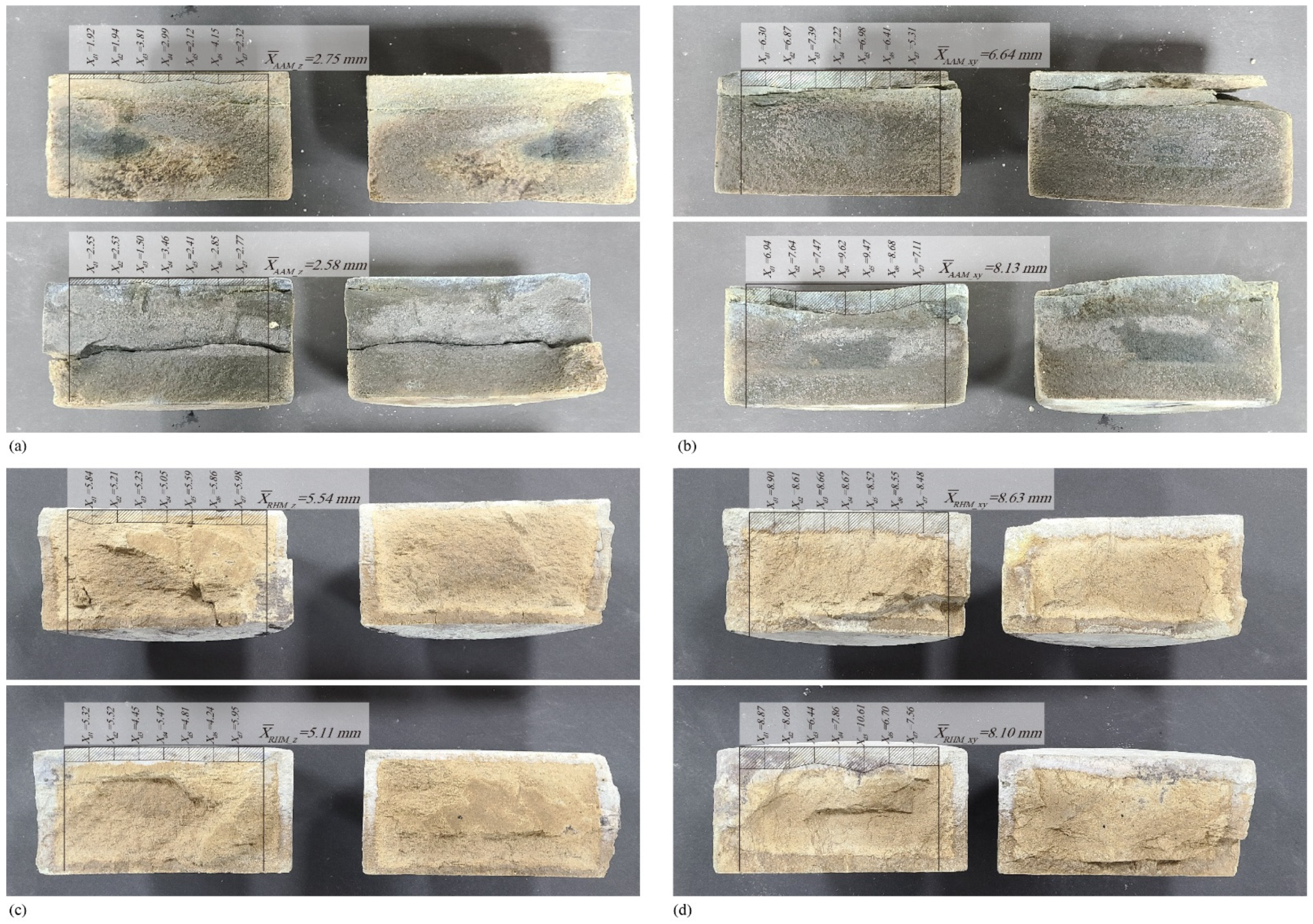
After splitting the specimens tested for 6 h under an applied voltage of 10 V, 0.1 N silver nitrate (AgNO
3) was applied to the specimens. The results are shown in
Figure 7. Chloride ions penetrated and reacted with silver nitrate at depths of 2.58–3.30 mm (
Figure 7a), 6.64–8.13 mm (
Figure 7b), 4.88–5.54 mm (
Figure 7c), and 7.99–8.63 mm (
Figure 7d). The measured chloride penetration depths were substituted into Equation (1). The obtained results are shown in
Table 3.
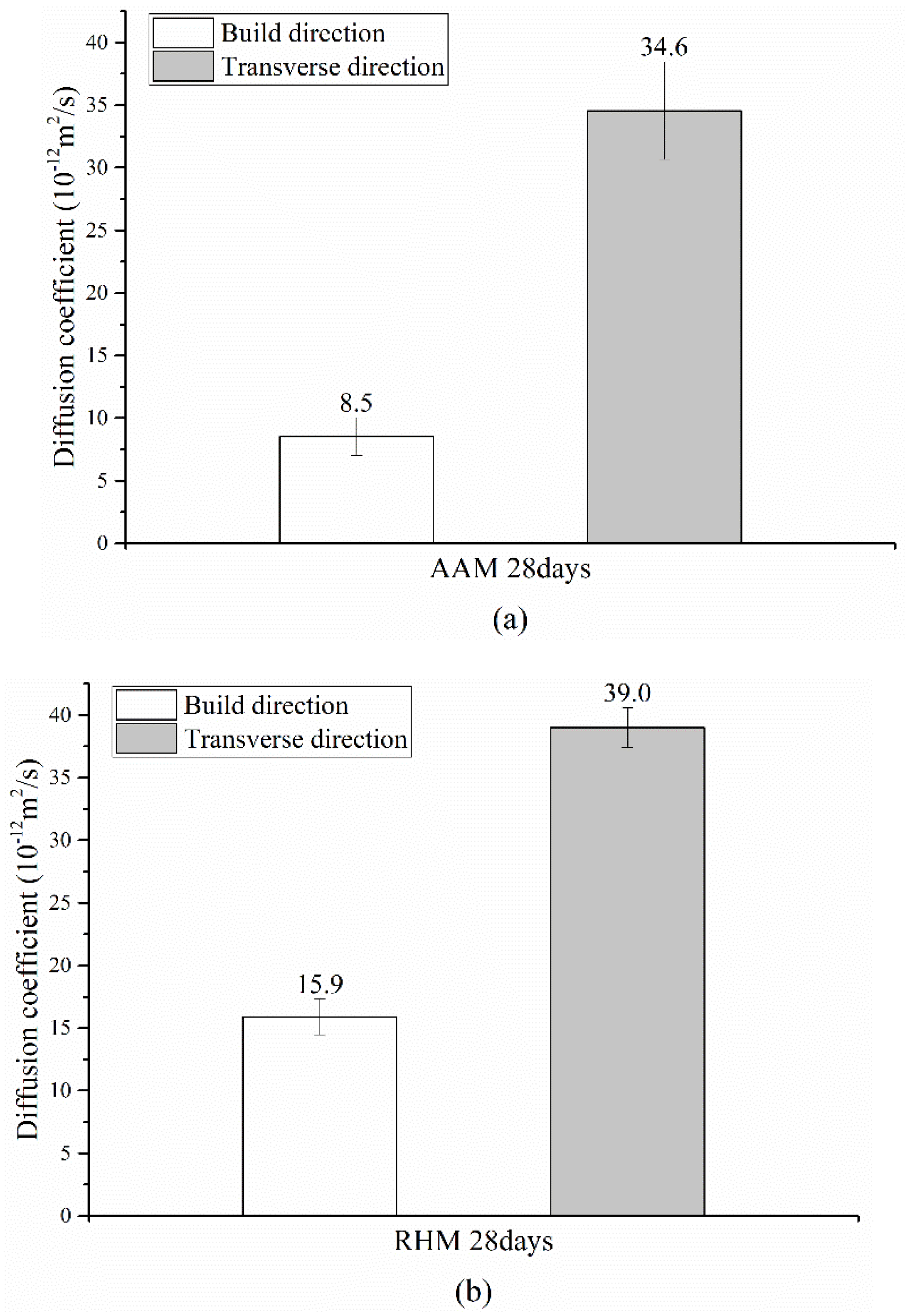
In the case of the AAM shown in
Figure 8a, chloride diffusion coefficients of 8.0–10.6 × 10
−12 m
2/s and 29.1–37.9 × 10
−12 m
2/s were measured in the build, and transverse directions, respectively, and the average diffusion coefficient in the transverse direction was 407.1% higher than that in the build direction. In the case of the RHM shown in
Figure 8b, chloride diffusion coefficients of 19.3–22.7 × 10
−12 m
2/s and 37.3–40.9 × 10
−12 m
2/s were measured in the build and transverse directions, respectively. The average diffusion coefficient in the transverse direction was 186.1% higher than that in the build direction.
It appears that the diffusion coefficient in the transverse direction was higher because gaps between layers were generated in the BJ3DP deposition process, and the gaps facilitated the chloride penetration. When printing was performed in the build direction, chloride diffusion decreased because the output direction was perpendicular to the chloride diffusion direction. However, when printing was performed in the transverse direction, chloride diffusion increased compared with that in the build direction because the output direction was parallel to the chloride diffusion direction. Nerella et al. [
51] also observed that the interface exhibits long and wide separations between the two neighboring layers.
4. Results and Discussion
In this study, the performance of the specimens produced using the binder jetting 3D printing (BJ3DP) method was evaluated with respect to the build orientation. The difference in performance depending on the build orientation was examined through the compressive strength and durability (chloride diffusion) tests. The conclusions drawn from this study are summarized as follows:
The compressive strength of the BJ3DP outputs was 22.1% to 26.5% lower in the transverse direction than in the build direction.
The chloride diffusion coefficient in the transverse direction was 186.1% to 407.1% higher than that in the build direction. Chloride diffusion appeared to decrease when printing was performed in the build direction because the output direction was perpendicular to the chloride diffusion direction. In contrast, it appeared to increase when printing was performed in the transverse direction because the output direction was parallel to the chloride diffusion direction.
In this study, the build orientation was limited to two types: build and transverse directions. The specimen curing age was also limited to 28 days. In the future, we will investigate the diversification of the build orientation (e.g., 15, 30, 45, 60, and 75°) and the long-term curing age after 28 days.
5. Conclusions
The influence of the output direction on the compressive strength ranges from 22.1% to 26.5%, whereas its influence on the durability performance ranges from 186.1% to 407.1%. This shows that the influence of the output direction on the long-term durability performance is greater than that on the short-term mechanical performance. Therefore, it is necessary to examine the output direction that can secure durability performance in advance for the long-term use (considering maintenance) of cementitious material-based 3D printing outputs. Therefore, when the BJ3DP outputs are produced based on cementitious materials, the initial design and manufacturing methods should be determined by examining the self-weight and external force directions in advance.
In this study, cementitious material-based outputs were additively manufactured using BJ3DP. Because AM exhibits different mechanical properties depending on the build orientation, the build orientation needs to be considered during design. It is also necessary to examine the build orientation in advance to satisfy the performance required for the use of cementitious material-based outputs as building members in the future. In further research on the design and manufacturing of building members using BJ3DP, we intend to set the output size, geometry, and material used as the research variables.
The separation of layer interface of BJ3DP caused by the loose microstructure with more and larger pores leads to the degradation of durability, and it will be considered in future work. Considering the importance of durability to the service life of concrete structures, research on the durability of BJ3DP needs to be emphasized.
Author Contributions
Conceptualization, K.-M.P.; writing—original draft, K.-M.P.; writing—review & editing, K.-M.P.; data curation, K.-S.M.; writing—original draft, K.-S.M.; formal analysis, K.-S.M.; methodology, K.-S.M.; visualization, K.-S.M.; project administration, B.-C.L.; supervision, B.-C.L. and Y.-S.R.; writing—review & editing, B.-C.L. All authors have read and agreed to the published version of the manuscript.
Funding
This work was supported by the Architecture & Urban Development Research Program funded by the Ministry of Land Infrastructure and Transport, Government of Korea (grant number 21 AUDP-B121595-06). The sponsor played a role in the development of innovative design, material, and equipment for the 3D printing of small buildings/freeform members.
Institutional Review Board Statement
Not applicable.
Informed Consent Statement
Not applicable.
Data Availability Statement
The data presented in this study are available from the corresponding author.
Conflicts of Interest
The authors declare no conflict of interest.
References
- Ford, S.; Despeisse, M. Additive Manufacturing and Sustainability: An Exploratory Study of the Advantages and Challenges. J. Clean. Prod. 2016, 137, 1573–1587. [Google Scholar] [CrossRef]
- ASTM F2792-12a. Standard Terminology for Additive Manufacturing Technologies; ASTM International: West Conshohocken, PA, USA, 2012. [Google Scholar]
- Martínez-García, A.; Monzón, M.; Paz, R. Standards for Additive Manufacturing Technologies: Structure and Impact. In Additive Manufacturing; Elsevier: Amsterdam, The Netherlands, 2021; pp. 395–408. [Google Scholar] [CrossRef]
- Del Giudice, L.; Vassiliou, M.F. Mechanical Properties of 3D Printed Material with Binder Jet Technology and Potential Applications of Additive Manufacturing in Seismic Testing of Structures. Addit. Manuf. 2020, 36, 101714. [Google Scholar] [CrossRef]
- Tang, Y.; Mak, K.; Zhao, Y.F. A Framework to Reduce Product Environmental Impact Through Design Optimization for Additive Manufacturing. J. Clean. Prod. 2016, 137, 1560–1572. [Google Scholar] [CrossRef]
- Han, Y.; Yang, Z.; Ding, T.; Xiao, J. Environmental and Economic Assessment on 3D Printed Buildings with Recycled Concrete. J. Clean. Prod. 2021, 278, 123884. [Google Scholar] [CrossRef]
- Park, K.M.; Lee, J.; Lee, B.C. Improvement in Strength of 3D Printed Alkali-Activated Slag/Fly Ash Paste. J. Korea Concr. Inst. 2018, 30, 641–648. [Google Scholar] [CrossRef]
- Gao, W.; Zhang, Y.; Ramanujan, D.; Ramani, K.; Chen, Y.; Williams, C.B.; Wang, C.C.L.; Shin, Y.C.; Zhang, S.; Zavattieri, P.D. The Status, Challenges, and Future of Additive Manufacturing in Engineering. Comput. Aided Des. 2015, 69, 65–89. [Google Scholar] [CrossRef]
- Buswell, R.A.; Soar, R.C.; Gibb, A.G.F.; Thorpe, A. Freeform Construction: Mega-Scale Rapid Manufacturing for Construction. Autom. Constr. 2007, 16, 224–231. [Google Scholar] [CrossRef] [Green Version]
- Vantyghem, G.; De Corte, W.; Shakour, E.; Amir, O. 3D Printing of a Post-Tensioned Concrete Girder Designed by Topology Optimization. Autom. Constr. 2020, 112, 103084. [Google Scholar] [CrossRef]
- Wang, L.; Gramlich, W.M.; Gardner, D.J. Improving the Impact Strength of Poly(Lactic Acid) (PLA) in Fused Layer Modeling (FLM). Polymers 2017, 114, 242–248. [Google Scholar] [CrossRef]
- McLouth, T.D.; Severino, J.V.; Adams, P.M.; Patel, D.N.; Zaldivar, R.J. The Impact of Print Orientation and Raster Pattern on Fracture Toughness in Additively Manufactured ABS. Addit. Manuf. 2017, 18, 103–109. [Google Scholar] [CrossRef]
- Kim, J.S.; Jo, N.; Nam, J.S.; Lee, S.W. Identification and Optimization of Dominant Process Parameters Affecting Mechanical Properties of FDM 3D Printed Parts. Trans. Korean Soc. Mech. Eng. A 2017, 41, 607–612. [Google Scholar] [CrossRef]
- Zaldivar, R.J.; Witkin, D.B.; McLouth, T.; Patel, D.N.; Schmitt, K.; Nokes, J.P. Influence of Processing and Orientation Print Effects on the Mechanical and Thermal Behavior of 3D-Printed ULTEM® 9085 Material. Addit. Manuf. 2017, 13, 71–80. [Google Scholar] [CrossRef]
- Feng, P.; Meng, X.; Chen, J.F.; Ye, L. Mechanical Properties of Structures 3D Printed with Cementitious Powders. Constr. Build. Mater. 2015, 93, 486–497. [Google Scholar] [CrossRef] [Green Version]
- Ingaglio, J.; Fox, J.; Naito, C.J.; Bocchini, P. Material Characteristics of Binder Jet 3D Printed Hydrated CSA Cement with the Addition of Fine Aggregates. Constr. Build. Mater. 2019, 206, 494–503. [Google Scholar] [CrossRef]
- Ziemian, C.W.; Ziemian, R.D.; Haile, K.V. Characterization of Stiffness Degradation Caused by Fatigue Damage of Additive Manufactured Parts. Mater. Des. 2016, 109, 209–218. [Google Scholar] [CrossRef] [Green Version]
- Jiang, D.; Smith, D.E. Anisotropic Mechanical Properties of Oriented Carbon Fiber Filled Polymer Composites Produced with Fused Filament Fabrication. Addit. Manuf. 2017, 18, 84–94. [Google Scholar] [CrossRef]
- Cuan-Urquizo, E.; Barocio, E.; Tejada-Ortigoza, V.; Pipes, R.B.; Rodriguez, C.A.; Roman-Flores, A. Characterization of the Mechanical Properties of FFF Structures and Materials: A Review on the Experimental, Computational and Theoretical Approaches. Materials 2019, 12, 895. [Google Scholar] [CrossRef] [PubMed] [Green Version]
- Cantrell, J.T.; Rohde, S.; Damiani, D.; Gurnani, R.; DiSandro, L.; Anton, J.; Young, A.; Jerez, A.; Steinbach, D.; Kroese, C.; et al. Experimental Characterization of the Mechanical Properties of 3D-printed ABS and Polycarbonate Parts. Rapid Prototyp. J. 2017, 23, 811–824. [Google Scholar] [CrossRef]
- Marchment, T.; Sanjayan, J. Mesh Reinforcing Method for 3D Concrete Printing. Autom. Constr. 2020, 109, 102992. [Google Scholar] [CrossRef]
- Baduge, S.K.; Navaratnam, S.; Abu-Zidan, Y.; McCormack, T.; Nguyen, K.; Mendis, P.; Zhang, G.; Aye, L. Improving Performance of Additive Manufactured (3D printed) Concrete: A Review on Material Mix Design, Processing, Interlayer Bonding, and Reinforcing Methods. Structures 2021, 29, 1597–1609. [Google Scholar] [CrossRef]
- Panda, B.; Paul, S.C.; Tan, M.J. Anisotropic Mechanical Performance of 3D Printed Fiber Reinforced Sustainable Construction Material. Mater. Lett. 2017, 209, 146–149. [Google Scholar] [CrossRef]
- Sikora, P.; Chougan, M.; Cuevas, K.; Liebscher, M.; Mechtcherine, V.; Ghaffar, S.H.; Stephan, D. The Effects of Nano- and Micro-sized Additives on 3D Printable Cementitious and Alkali-Activated Composites: A Review. Appl. Nanosci. 2021, 1–19. [Google Scholar] [CrossRef]
- Gibbons, G.J.; Williams, R.; Purnell, P.; Farahi, E. 3D Printing of Cement Composites. Adv. Appl. Ceram. 2010, 109, 287–290. [Google Scholar] [CrossRef] [Green Version]
- Cesaretti, G.; Dini, E.; De Kestelier, X.; Colla, V.; Pambaguian, L. Building Components for an Outpost on the Lunar Soil by Means of a Novel 3D Printing Technology. Acta Astronaut. 2014, 93, 430–450. [Google Scholar] [CrossRef]
- Maier, A.K.; Dezmirean, L.; Will, J.; Greil, P. Three-Dimensional Printing of Flash-Setting Calcium Aluminate Cement. J. Mater. Sci. 2011, 46, 2947–2954. [Google Scholar] [CrossRef]
- Bose, S.; Vahabzadeh, S.; Bandyopadhyay, A. Bone Tissue Engineering Using 3D Printing. Mater. Today 2013, 16, 496–504. [Google Scholar] [CrossRef]
- Brunello, G.; Sivolella, S.; Meneghello, R.; Ferroni, L.; Gardin, C.; Piattelli, A.; Zavan, B.; Bressan, E. Powder-Based 3D Printing for Bone Tissue Engineering. Biotechnol. Adv. 2016, 34, 740–753. [Google Scholar] [CrossRef] [PubMed]
- Butscher, A.; Bohner, M.; Hofmann, S.; Gauckler, L.; Müller, R. Structural and Material Approaches to Bone Tissue Engineering in Powder-Based Three-Dimensional Printing. Acta Biomater. 2011, 7, 907–920. [Google Scholar] [CrossRef]
- Voney, V.; Odaglia, P.; Brumaud, C.; Dillenburger, B.; Habert, G. Geopolymer Formulation for Binder Jet 3D Printing. In Proceedings of the Second RILEM International Conference on Concrete and Digital Fabrication, Online Event, 6–9 July 2020; Springer: Cham, Switzerland, 2020; pp. 153–161. [Google Scholar] [CrossRef]
- Park, K.M.; Park, S.H.; Lee, J.; Lee, B.C.; Roh, Y.S. Evaluation of Binder Jetting 3D Printed Specimens Using Vacuum Impregnation. J. Korea Inst. Struct. Maint. Inspect. 2020, 24, 103–110. [Google Scholar] [CrossRef]
- Farzadi, A.; Solati-Hashjin, M.; Asadi-Eydivand, M.; Abu Osman, N.A.A. Effect of Layer Thickness and Printing Orientation on Mechanical Properties and Dimensional Accuracy of 3D Printed Porous Samples for Bone Tissue Engineering. PLoS ONE 2014, 9, e108252. [Google Scholar] [CrossRef] [PubMed]
- Gaytan, S.M.; Cadena, M.A.; Karim, H.; Delfin, D.; Lin, Y.; Espalin, D.; MacDonald, E.; Wicker, R.B. Fabrication of Barium Titanate by Binder Jetting Additive Manufacturing Technology. Ceram. Int. 2015, 41, 6610–6619. [Google Scholar] [CrossRef] [Green Version]
- Ziaee, M.; Crane, N.B. Binder Jetting: A Review of Process, Materials, and Methods. Addit. Manuf. 2019, 28, 781–801. [Google Scholar] [CrossRef]
- Rossi, E.; Polder, R.; Copuroglu, O.; Nijland, T.; Šavija, B. The Influence of Defects at the Steel/Concrete Interface for Chloride-induced Pitting Corrosion of Naturally-deteriorated 20-years-old Specimens Studied Through X-ray Computed Tomography. Constr. Build. Mater. 2020, 235, 117474. [Google Scholar] [CrossRef]
- Gu, C.P.; Ye, G.; Sun, W. A review of the chloride transport properties of cracked concrete: Experiments and simulations. J. Zhejiang Univ. Sci. A 2015, 16, 81–92. [Google Scholar] [CrossRef]
- Gao, Y.H.; Zhang, J.Z.; Zhang, S.; Zhang, Y.R. Probability distribution of convection zone depth of chloride in concrete in a marine tidal environment. Constr. Build. Mater. 2017, 140, 485–495. [Google Scholar] [CrossRef]
- Lim, J.H.; Panda, B.; Pham, Q.C. Improving Flexural Characteristics of 3D Printed Geopolymer Composites with In-process Steel Cable Reinforcement. Constr. Build. Mater. 2018, 178, 32–41. [Google Scholar] [CrossRef]
- Gebhard, L.; Mata-Falcón, J.; Anton, A.; Dillenburger, B.; Kaufmann, W. Structural Behaviour of 3D Printed Concrete Beams with Various Reinforcement Strategies. Eng. Struct. 2021, 240, 112380. [Google Scholar] [CrossRef]
- Baz, B.; Aouad, G.; Kleib, J.; Bulteel, D.; Remond, S. Durability Assessment and Microstructural Analysis of 3D Printed Concrete Exposed to Sulfuric Acid Environments. Constr. Build. Mater. 2021, 290, 123220. [Google Scholar] [CrossRef]
- Wangler, T.; Roussel, N.; Bos, F.P.; Salet, T.A.; Flatt, R.J. Digital Concrete: A Review. Cem. Concr. Res. 2019, 123, 105780. [Google Scholar] [CrossRef]
- Van Der Putten, J.; De Volder, M.; Van den Heede, P.; De Schutter, G.; Van Tittelboom, K. 3D printing of concrete: The influence on chloride penetration. In Proceedings of the Second RILEM International Conference on Concrete and Digital Fabrication, Online Event, 6–9 July 2020; Springer: Cham, Switzerland, 2020; pp. 500–507. [Google Scholar] [CrossRef]
- Build, N. Concrete, Mortar and Cement-Based Repair Materials: Chloride Migration Coefficient from Non-Steady-State Migration Experiments. Nordtest Method. 1999, 492, 492. [Google Scholar]
- Kim, K.; Park, S.; Kim, W.; Jeong, Y.; Lee, J. Evaluation of Shear Strength of RC Beams with Multiple Interfaces Formed Before Initial Setting Using 3D Printing Technology. Materials 2017, 10, 1349. [Google Scholar] [CrossRef] [Green Version]
- Utela, B.; Storti, D.; Anderson, R.; Ganter, M. A Review of Process Development Steps for New Material Systems in Three Dimensional Printing (3DP). J. Manuf. Process. 2008, 10, 96–104. [Google Scholar] [CrossRef]
- Ngo, T.D.; Kashani, A.; Imbalzano, G.; Nguyen, K.T.Q.; Hui, D. Additive Manufacturing (3D Printing): A Review of Materials, Methods, Applications and Challenges. Compos. B Eng. 2018, 143, 172–196. [Google Scholar] [CrossRef]
- 3D Systems. ZB63 Safety Data Sheet. Available online: http://infocenter.3dsystems.com/materials/auxiliary/binder (accessed on 4 October 2021).
- Shakor, P.; Sanjayan, J.; Nazari, A.; Nejadi, S. Modified 3D Printed Powder to Cement-Based Material and Mechanical Properties of Cement Scaffold Used in 3D Printing. Constr. Build. Mater. 2017, 138, 398–409. [Google Scholar] [CrossRef]
- KS L ISO 679. Methods of Testing Cements—Determination of Strength; British Standards: London, UK, 2016; pp. 12–16. [Google Scholar]
- Nerella, V.N.; Hempel, S.; Mechtcherine, V. Effects of Layer-interface Properties on Mechanical Performance of Concrete Elements Produced by Extrusion-based 3D-printing. Constr. Build. Mater. 2019, 205, 586–601. [Google Scholar] [CrossRef]
| Publisher’s Note: MDPI stays neutral with regard to jurisdictional claims in published maps and institutional affiliations. |
© 2021 by the authors. Licensee MDPI, Basel, Switzerland. This article is an open access article distributed under the terms and conditions of the Creative Commons Attribution (CC BY) license (https://creativecommons.org/licenses/by/4.0/).


